■LÍGMTING O F ОРЕЫ
5 *£■ rí. , "* ·“'
Λ'· ÏC^J= V -^¿ ^£<^ 'J']5’:£í<í£i^'
LIGHTING OF OPEN PLAN (AUTOMATED) OFFICES
A THESIS
SUBMITTED TO THE DEPARTMENT OF INTERIOR ARCHITECTURE AND
ENVIRONMENTAL DESIGN
AND INSTITUTE OF FINE ARTS OF BILKENT UNIVERSITY IN PARTIAL FULFILLMENT OF THE REQUIREMENTS
FOR THE DEGREE OF MASTER OF FINE ARTS
By İlkin Öner January, 1995
-Т |/
■ 0 2 ,1
с
I certify that I have read this thesis and in my own opinion it is fully adequate, in scope and in quality, as a thesis for the degree of Master of Fine Arts.
I certify that I have read this thesis and in my own opinion it is fully adequate, in scope and in quality, as a thesis for the degree of Master of Fine Arts.
Prof. Dr. Mustafa Pultar
I certify that I have read this thesis and in my own opinion it is fully adequate, in scope and in quality, as a thesis for the degree of Master of Fine Arts.
Assfstl Prof. l-|Qlime Demirkan
Approved by the Institute of Fine Arts
ABSTRACT
LIGHTING OF OPEN PLAN (AUTOMATED) OFFICES
İlkin Öner M.F.A.
in
Interior Architecture and Environmental Design Supervisor: Assoc. Prof. Dr. Cengiz Yener
January, 1995
Lighting in Open Plan (Automated) offices is an important factor for the workers performance and productivity. Generally, physiological and psychological requirements of the office lighting are being neglected while designing or relocating of the office environment. Hence, offices become unpleasant places to work in. The aim of this study is to analyze lighting requirements of open plan automated offices and to prepare a set of criteria for the lighting design of these spaces.
Keywords: Lighting, Open Office, Workplace, VDT (Video Display Terminal), Workstation.
ÖZET
AÇIK PLAN OFİS AYDINLATMASI
İlkin öner
İç Mimarlık ve Çevre Tasarımı Bölümü Yüksek Lisans
Tez Yöneticisi: Doç. Dr. Cengiz Yener Ocak, 1995
Yoğun bilgisayar kullanılan açık planlı ofislerde, aydınlatma, çalışanların performansları ve verimlilikleri yönünden önemli bir etkendir. Genellikle ofis tasarlanırken ya da yeniden düzenlenirken, aydınlatmanın fizyolojik ve psikolojik yönden gereksinimleri ihmal edilmektedir. Bu yüzden de ofisler, hoş olmayan çalışma alanları haline gelmektedirler. Bu çalışmanın amacı, . elektronik donanımlı açık planlı ofislerdeki aydınlatma gereklerini inceleyerek, bu alanların aydınlatma tasarımında kullanılabilecek kriterleri saptamaktır.
Anahtar Sözcükler: Aydınlatma, Açık Ofis, Çalışma Alanı, Bilgisayar,
Çalışma İstasyonu.
ACKNOWLEDGEMENTS
I would like to thank to all precious people who are supported me during this study continuously and patiently. What I know is that I have learned from them a lot. So, for me the word " thanks" is not enough for them. I am not mentioning their names here. But, for those who are interested, they are those who knows the importance of the story about the man, at the seashore, collecting seastars patiently, and throwing them to the sea in order to prevent their dying.
ABSTRACT... ijj
ÖZET... iv
ACKNOWLEDGEMENTS... v
TABLE OF CONTENTS... vi
LIST OF TABLES... viii
LIST OF FIGURES... ix
LIST OF SYMBOLS... xii
1. INTRODUCTION... 1
2. SPECIFIC ACTIVITY AREAS IN OPEN-AUTOMATED OFFICES... 4
2.1 Work Areas... 5
2.1.1. VDT Work, Reading and Hardcopy... 6
2.1.2. Visual Display Terminals and their Uses... 8
2.1.3. Problems with VDT Workstations... 12
2.2. Commitee Rooms... 13
2.3. Adjoining Areas... 14
3. METHODS OF LIGHTING OF OPEN-AUTOMATED OFFICES... 15
3.1. Natural Lighting of Open-Automated Offices... 15
3.1.1. Size, Shape and Treatment of Light Source... 17
3.1.2. Control Methods... 27
3.2. Artificial lighting of Open-Automated Offices... 33
3.2.1. Direct Lighting... 34 3.2.2. Indirect Lighting... 41 3.2.3. Direct/Indirect Lighting... 49 3.2.4. Control Methods... 50 TABLE OF CONTENTS VI
4. PHYSIOLOGICAL REQUIREMENTS OF OPEN-AUTOMATED
OFFICE LIGHTING... 54
4.1. Glare Avoidance... 54
4.2. Factors Affecting Luminance... 62
4.2.1. Texture and Finishes... 67
4.2.2. Color Variations... 69
4.3. Quantity of Illumination... 71
4.4. Artificial Light Sources... 74
4.4.1. Color Temperature... 77 4.4.2. Color rendering... 79 5. PSYCHOLOGICAL REQUIREMENTS OF OPEN-AUTOMATED OFFICES... 81 5.1. Spaciousness... 83 5.2. Pleasantness... 85 5.3. Visual Clarity... 89 5.4. Relaxation... 89
5. GENERAL CRITERIA FOR LIGHTING OF OPEN-AUTOMATED OFFICES... 91
6. CONCLUSION... 102
APPENDIX (Definitions)... 105
LIST OF TABLES
Table Page
Table 3.1 Daylight Media for Workplaces... 28
Table 3.2 Screen to Ceiling Sight-Line Angles
from Vertical in Degrees... 37
Table 4.1 Luminance Values for the Experimented
Computers... 66
Table 4.2 Recommended Reflections for VDT
Environments... 68
Table 4.3 Color Specifications for the Offices by Munsell
Notation... 70
Table 4.4 Recommended Illumination Levels at VDT
Workstations (The lux values refer to measures
taken on a horizontal plane)... 73 Table 5.1 Brightness Ratios... 82
LIST OF FIGURES Figure Page Figure 2.1 Figure 2.2 Figure 2.3 Figure 3.1 Figure 3.2 Figure 3.3 Figure 3.4 Figure 3.5 Figure 3.6 Figure 3.7 Figure 3.8 Figure 3.9 Figure 3.10 Figure 3.11 Figure 3.12 Figure 3.13 Figure 3.14 Figure 3.15 Conventional Workstation... 6 Automated Workstation... 6
Background Reflections on VDT Screen for Positive and Negative Contrast Screens... 10
Lightshelves... 20
Window with Splayed Reveals... 21
North and South Facing Monitors... 22
Sawtooth Monitor... 23
Monitor with Vertical Glazing Combined with an Overhang... 23
Skylight Below Ceiling Plane... 24
A typical Flat, Translucent Skylight... 24
Skylight with a sloped reflectors below ceiling plane... 24
A Sloped Skylight... 25
Combinations of Daylight Media... 25
Combined System (daylight and electric lighting)... 28
Overhang Constructed with Vertical Louvers... 29
Overhang Constructed with Horizontal Louvers... 29
Skylight and the Loft System of the Open-Automated Office... 31
Figure 3.16 Typical Geometry for Eye, Screen and Luminaire... 36
Figure 3.17 Ceiling Lighting Generating a Cone of Light with an Angle of 45 Degree to the Vertical... 38
Figure 3.18 Vaulted Ceiling System... 39
Figure 3.19 Open Office with Downlight Installation... 40
Figure 3.20 Lighting Method of Wall Mounted Charts in Conference Room... 41
Figure 3.21 Comparison of Screen Reflections from Direct and Indirect Luminaires... 43
Figure 3.22 Task Light with a Batwing Lens... 44
Figure 3.23 Free-Standing Uplighters... 45
Figure 3.24 Wall Mounted Uplighters... 45
Figure 3.25 Uplighters Suspended from Ceiling... 45
Figure 3.26 Uplighters with a Wide and Narrow Light Distribution... 46
Figure 3.27 Compound Parabolic Direct Lighting System... 47
Figure 4.1 Reflected Image of a Window and a Light Source on Screen... 55
Figure 4.2 Specular and Diffuse Reflections... 56
Figure 4.3 Egg-crate Louver... 59
Figure 4.4 Parabolic Louver... 59
Figure 4.5 Shadows From Sharp Cut-Off Luminaires... 59
Figure 4.6 Excessive Luminance Contrasts in the Visual Environment of a VDT Operator... 63
Figure 4.7 Acceptable Contrast Ratios of Brightness Between Different Area of the Visual Field... 64
Figure 4.8 Plan of the Laboratory and the Location of the Computers... 65
Figure 4.9 The Points of Measurements on and around
the VDTs... 66
Figure 4.10 Recommended Reflectances for Open Offices... 68
Figure 4.11 Recommended Reflectances for VDT
Workstation with a Positive Contrast Screen... 68
Figure 4.12 Color Appearance... 78
Figure 5.1 An Uninteresting Committee Room... 82
Figure 5.2 Descriptions of Setting and Lighting
Arrangement... 84 Figure 5.3 Gloomy Interior... 88
LIST OF SYMBOLS
CCR Correlated Color Temperature.
CRT Cathode Ray Tube.
CW Cool White
CWX Deluxe Cool White
DX Deluxe White
HID High Intensity Discharge.
IES Illuminating Engineering Society.
K Kelvin.
LIL Lensed-direct Uplighting.
Low-E Low-emissivity.
MR Multi-reflector.
PAR Parabolis Aluminized Reflector.
PBS Recessed Parabolic Downlighting.
Ra Color Rendering Index
SPD Spectral Power Distribution
VDT Video Display Terminal.
VDU Video Display Unit.
WWX Warm White Deluxe
1. INTRODUCTION
Today, computers have become an important part of our work environment, and thus our daily life. In Turkey, the use of computers are steadily infiltrating the office environment. Nowadays, almost in every bank, travel agency and other big business corporation's headquarters these machines are used extensively. As the use of computers in the offices is increasing, at the same time, there is seen a wide preference of designing open-plan type of offices.
In open office planning, initially, free standing screens are utilized. In all cases, the open office utilizes partly-high space dividers. Today, most of the open-plan offices include private and group offices, beside the continuos open plan space. This mix of closed and open plan offices has added a new dimension to design and performance issues. The fundamental distinction between them is simple but meaningful one: partitioning. In the closed system partitions between workplaces are interior walls that extend from floor to ceiling. In the open system, partitions, generally in the form of visual/acoustical screens, do not extend to the ceiling. The screens rarely above 150 cm, and may not be flush with the floor (Harris, et. al., 1991). Open plan office provides facilitated communication between individuals and groups, and stimulated work among workers. In addition, it provides great ease in the distribution of power in the office. Also, because of the rapid changes in the organization systems, flexibility becomes one of the most important requirements in the office planning, and thus, open office seems to be the most appropriate planning for the automated office.
Generally, in the design of new automated offiœ s or while adapting the
existing ones to the needs of the newly developed technology, the
importance of some factors is overlooked. Most of the time, the workers' visual needs come after the organization's and tools' requirements. Hence, usually offices are not very pleasant spaces to work in. Lighting is an inevitable element in the office design which directly affects the worker's performance and productivity. Thus, it should be considered seriously in the design of any automated office.
In addition. Visual Display Terminals (VDTs) may bring important problems as a consequence of their interrelation with lighting system, since their screens may act as a both light source and a reflecting surface. Glare and veiling reflections can occur on the VDT screen as a result of the careless placement of the VDT screen in relation to the light sources (such as luminaires, windows, etc.) in an environment designed for the paper-based work. As the line of sight for the VDT use is inclined more towards the horizontal than it is for the tasks performed on a desk, light required for each task varies.
On the other hand, it is clear that a pleasant working environment w ill result in a higher level of productivity. Different lighting patterns draw out various subjective impressions like spaciousness, pleasantness, etc., and affect our visual perception. Especially, in open plan offices light should help to the identification of circulation patterns and activity areas by providing appropriate visual cues. So, psychological requirements are also of important factors that need to be considered. This picture confirms that lighting of an automated office needs to be handled with great care, and with this thesis it is planned to set some criteria related with the lighting design of the open-automated offices.
This study is based upon a literature survey. In the second chapter, mainly the work areas, and to a small extent meeting and adjoining areas like corridors and waiting areas are examined from the lighting point of view. Other areas in the open office are not in the concern of this thesis. Third chapter discusses the lighting systems of open-planned offices (natural and artificial), and the control methods of these systems. The concern of the
fourth chapter is physiological lighting requirements such as glare
avoidance, quantity of illumination, luminance and factors affecting luminance, and light sources used in office areas. Also, the results of a small investigation that is done in the computer laboratory of the Faculty of Art, Design and Architecture of Bilkent University will be given in this chapter. For the investigation, luminance levels around selected terminals are measured with luminance meter (Minolta, LS 100). These terminals are situated at different areas in the laboratory. Results taken from each terminal are compared with the reference values taken from Grandjean (1987, p.43) in order to decide on whether measured conditions are suitable or not. In the fifth chapter, psychological requirements of open-planned office are discussed, since the lighting design of the environment can be crucial identifier in determining visual meaning by affecting the subjective impressions such as spaciousness, visual clarity, pleasantness, relaxation, etc. A general criteria for the lighting design of open-automaited offices that
Many reasons are presented for using an open-plan type of design approach by the authorities. It provides facilitated communications in between individuals and groups, stimulated work among the workers, and stresses the egalitarian values. On the other hand, there are some reasons for not using an open-plan concept entirely. Generally, highly skilled professionals needed more privacy to perform their work. Besides, private spaces offered security and a place to get away. After careful consideration, a modified closed system was developed. Full-height office spaces were designed for professionals, with one glass partition with vertical shades to close if users needed or desired greater privacy. Also, designing workstations having more enclosure and territory for secretarial employees was also recommended
within a modified open-space concept (Harris et.al., 1991). Also, Duffy
points out that in Sweden and West Germany, where the open plan was once so popular, many new office buildings are being constructed with private offices and group offices, rather than continuous open plan (Duffy cited in Kleeman et.al., 1991).
2. SPECIFIC ACTIVITY AREAS IN OPEN-AUTOMATED OFFICES
In open offices, spaces are generally categorized according to the activities that is going to be performed in this area. In this thesis, only work areas, conference areas, and adjoining areas are going to be considered from lighting point of view.
In today's office, whether it be a secretarial or data-processing station or the office of a chief executive of an organization, the workstation is the basic unit of office planning and layout. From ergonomics standpoint, it is considered that the workstation is the domain of the individual and must be planned and designed to meet the varying requirements. The specific placement of components; computer terminals, communication devices, task-support tools, storage facilities, work-display surfaces, book-support
facilities, light fixtures, requires a consideration in order to provide the
requirements for physical comfort. Manual controls must be designed to accommodate the movements required to perform a given task (Rubin, 1986). In order to satisfy the environmental and ergonomic needs, and because of the varied visual tasks involved, efforts should be concentrated on providing an adjustable visual environment of improved quality, in and around each work station.
2.1. Work Areas.
Workstations are well-equipped and well-defined working areas. They are generally semi-closed and may accommodate one or more people (Farivarsadri, 1992). In the past, each workstation in a conventional office had a more or less 'fixed' visual task orientation e.g. functions involving reading and writing, reading and typing, audio typing, etc., (Figure 2.1). Today workstations (automated) are required to cover multi-functional
aspect such as reading and writing, word processing and typing,
computerized data retrieval and filing, face-4o-face discussion, etc., (Figure 2.2). Visibility for these tasks varies greatly from excellent to very poor, ^s much attention needs to be applied to improving the quality of th^ task as is
given to improving the lighting system to adapt the human eye to the various tasks (Harris, et.al.,1991).
Figure 2.1 Conventional workstation. (Pulgram and Stonis, 1984, p.125)
VO T IN T E C n A lE D
HiLEPMONE
SLOTTED W ORK SURFACE
, TEXTURED FIN ISH
...GUEST CHAIR
_ PERSONAL STORAGE
Figure 2.2 Automated workstation. (Pulgram and Stonis, 1984, p.125)
2.1.1. VDT W ork, Reading and Hard copy:
Until recently, terminal use environments were poorly understood. It is identified that there are four basic ways of employing terminals in an
organization: namely, regional terminals, satellite terminals, cluster terminals, dedicated terminals. In open offices, usually dedicated type of system is being used. Those terminals are placed in a workstation for the use of only one worker. They can be optimally located for this purpose and normally found when 20 percent or more of a worker's tasks require terminal usage (Galitz, 1984). As the information in today's office move from a paper- based to an electronic-based medium, the characteristics of information are changing in both substance and style. Information displayed on paper is legible and readable. The matte surface of paper diffuses reflected light, scarcely affecting the quality of the material presented. Paper-based information may be read under a variety of lighting conditions. In contrast, VDT characters are luminous and often of a dot-matrix construction. The character image may be blurred by dust on the VDT screen or by reflections from overhead lights or windows. Papers are normally read horizontally, such as resting on a desk top. They may be read vertically, however, by physically raising the paper to a position perpendicular to the eye. Because of the internal mechanics and problems with light reflections VDT's have little flexibility compared to paper, and they are read in a vertical plane. Papers are normally completed by hand, while VDT's through the use of a keyboard. W riting skills are far more than a keying skills. When writing, a person's eyes follow the hands, providing the immediate feedback. When keying, the hands operate in a different visual plane than that of the information display. Therefore, keying is a more complex visual task. Paper can easily be manipulated by moving it into a comfortable viewing position. On the other hand, VDT's are difficult to move and usually viewer modifies his or her viewing angles and distances only by posture changes. A hard copy is perceptually permanent whereas the information on a VDT screen is transient. Display of information on a VDT is limited by the boundaries or size of the display area. Often information must be presented serially as a
string of snapshots viewed in sequence. The breadth of display of paper
information is only restricted by the physical size of the work area. In
general, reading information on a display screen necessitates greater visual requirements than does reading information on a piece of paper (Galitz, 1984). With the introduction of VDT's into the workplace, occupants in offices have become much more aware of the lighting system and its performance. The VDT is very sensitive to veiling reflections, and this directly affects the performance of the worker. Lighting designs with marginal performance are no longer acceptable, and so, the VDT is a very common item that can not be ignored in the design process (Harris, et.al.,
1991).
2.1.2. Visual Display Terminals and Their Uses
To understand the problems of correct lighting for VDT's, the available types of VDTs and their applications in the modern working environment should be considered first. Traditional office functions involved working on paper on a flat horizontal desks. The majority of VDTs have brought part of this work task, the reading of text, to a near vertical position. The VDT has a keyboard: separate from the VDT screen, and this is used for writing or controlling the screen. The need to consult with written text, screen text and the keyboard means that the users adapt different postures to those associated with working on a flat desk. The front element of the screen tends to act as a partial mirror. It reflects back to the user an image of what is in front of the screen. If this image is nearly as bright as the screen characters, it starts to compete and thus makes the text difficult to read. Although most modern screens have a anti-reflection finish, which helps to diffuse any sharp images that appear on the screen, the invisibility of the
reflected images on the VDT screen becomes important issue that should be considered carefully.
In order to be visible, an object must have a luminous (or color) contrast with its background, that is, the object brightness and the background brightness must be different from each other. There is a need of a minimum contrast that must be exceeded for the perception; contrast values below this
threshold are functionally invisible. Contrast threshold depends on a
number of factors, including the size of the object, how long the object was
seen and the overall adaptation level of the visual system. Contrast
threshold can be taken as a representative criterion for defining the
visibility, or rather invisibility, of reflected images on the VDT screens (Rea, 1991).
Most VDT screens are self luminous; that is, they produce light by
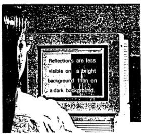
electrically stimulating phosphors on the VDT display. There are two kinds of displays: dark background displays (positive contrast displays) those have an average screen luminance of 5 to 10 cd/m=* in the dark, and bright background displays (negative contrast displays) those have a comparable luminance of 100 cd/m^ Rea (1991) explains the probability of reflected images occur on each type of display:
Glass or an untreated VDT screen will reflect about 8 percent of the light incident on it. An object with contrast of, say, 33 percent and a maximum luminance of 100 cd/m^ will produce a much more visible reflection in a dark background displays (of 10 cd/m^, for example) than in a bright background display (of 100 cd/m^ ). In both cases, 8 percent of the light from the object is reflected from the screen. The (maximum) luminance of the reflection (8 cd/m^) is close to the luminance of the dark background
display and will clearly seen. For the bright background display, however, this is a small amount of light relative to its self-generated light (p.36).
So it can be said that negative contrast displays work rather well in reducing many distracting reflections from the VDT environment. However, because the upper limit of luminance from this type of display is approximately 100 cd/m^, they will not be effective for very bright, high contrast objects such as untreated windows. It can be said that the negative contrast displays should have the advantage of reducing the luminance contrast ratio between the screen and source document. Also, as mentioned above, reflections on the glass surface screens should be less disturbing on displays with dark characters and bright background (Figure 2.3). However, because the upper limit of luminance from this type of display is approximately 100 cd/m^ , they will not be effective for very bright, high contrast objects. Untreated windows and many forms of electric lighting will still have the probability of producing reflections.
Cathode ray tube is the most common screen type, and used in television sets as well as in micro-computer terminals. It has generally slightly convex screen due to the way the image is produced on it. As the technology improves, these screens become squarer and flatter, in a similar manner to the latest television screens. The introduction of high resolution screens for graphics presentation have made the avoidance of reflections even more difficult, because the screen generally has no anti- reflection treatment so as not to degrade the image. Thus leaving what is in effect a large clear semi mirror in front of the screen - an image that is required to be the highest quality and resolution (CIBSE, Lighting Guide; Areas for Visual Display Terminals, 1989). Another common type of display is the flat liquid crystal display. It is used mostly on electronic typewriters and portable micro computers. Its screen has a flat shiny surface which makes it particularly difficult to light without causing reflections. Whatever the type of screen, it is generally mounted in a housing that allows some tilt and swivel adjustment. This helps the user to avoid unwanted reflections on the screen.
The keyboard , most frequently, is the means of data entry and control of individual VDTs. Most keyboards are now contained in a low unit, separate from the screen console. This allows the user to move the keyboard to a comfortable operating position. The keyboard can cause distracting reflections, sometimes referred as twinkle, if the key surface is glossy. The better types of keyboard have matte surface keys with the characters in a bold contrasting color. The surrounding of the keys is normally matte, to avoid reflections, and of a similar color and reflectance to the keys, to avoid large luminance contrasts with the keys.
In wide range of applications, from simple display of calculations to complex graphical representations, the terminals are used. Thp display itself may be
used during the day, to check data or receive electronic messages, or may be the entire work task, such as graphics design, data entry or retrieval. For non-critical or occasional use the user may be prepared to accept a slightly degraded image or some postural adjustment to avoid screen images. But where the information on the screen may be of the great importance, such as in control rooms, it is very important to avoid distracting or covering images on the screen (CIBSE, Lighting Guide: Areas for VDTs, 1989).
2.1.3. Problems with the VDT Workstations
In all office automation systems, the VDT is the basic device which is used, and it is therefore not suprising that it has received considerable attention by ergonomics researchers. According to them, it should be considered that the designs of the terminals accommodate the operators miscellaneous needs. Brown and his colleagues (1982), in a symposium conducted by the National Research Council of the National Academy of Sciences, indicate that the most common complaint expressed by the VDT operators is visual fatigue. The term is used to describe symptoms of ocular irritation, burning, blurring of images, and double vision: for the most part of these changes are temporary, according to current research findings (Black et.al., 1986).
The quality of the cathode ray tube (CRT) system, general lighting conditions, workspace design, and job-related factors are the components contribute to visual fatigue. VDT terminals placed in environments designed for desktop work, are the cause of lighting problems because VDT displays create new geometrical relationship between the work surfaces resulting in visual problems. So the reflected images on the VDT screen happens to be the main problem. VDT displays usually provide two competing images for
the worker's attention; it provides a view of the electronically generated alphanumeric text, drawings and pictures, and also, a view of the luminous environment surrounding the worker and the VDT, through reflection. These two images are at different optical distances: the electronically generated image is close while the reflected image is usually much further away. So the eye of the worker has to do repetitive focusing (Rea, 1991). In essence all successful design solutions for environments containing VDT's must eliminate or reduce the quality of the reflected image while maintaining the quality of the electronically generated image.
2.2. Committee Rooms.
Committee rooms are the places used for meetings capable of seating up to roughly thirty persons (CIBSE Lighting Guide; The Visual Environment in Lecture, Teaching and Conference Rooms, 1991). To be able to see each other properly, and to see what is going on are important needs for the
people gathered for the purposes of discussion. It is possible to see
occupants having a grotesque appearance because of a bad lighting, or a well prepared demonstration can be ruined by an uncontrolled ingress of sunlight. It is important that lighting system should allow members to read their papers and take notes properly, and supply a good visibility of wall mounted displays. Committees sometimes have to work under some stress, especially when unpleasant or unpopular decisions have to be made. So lighting is a vital element in such rooms and requirements of lighting should be taken into account from the first stages of the planning.
2.3. Adjoining Spaces
Corridors, lobbies, and waiting areas are known as adjoining spaces. The lighting in such areas is responsible for providing guidance for the visitor from entrance to a destination. In some cases, especially waiting areas and ante-rooms can be used as tea and coffee spaces, so lighting can provide a social atmosphere In these areas and can put users, as they approach, in an appropriate frame of mind for the activity in they are about to take part (CIBSE Lighting Guide: The Visual Environment in Lecture, Teaching and Conference Rooms, 1991)
3. METHODS OF OPEN-AUTOMATED OFFICE LIGHTING
Visible electromagnetic energy (light), when produced by man-made mechanisms is constant in its properties and its hours of availability is controllable. Spectral composition of light produced by electric lamps differs from that of daylight. Daylight varies continuously in its direction, intensity and color properties throughout the day. Its hours of availability changes with season and latitude and the illuminance varies with changing weather. Because of its variability, daylight may produce different visual conditions throughout the day changing from ideal to unsuitable for the working condition in an office. Whereas because of its controllability, electric lighting can be designed to produce excellent visual conditions continuously in any location (Lyons, 1992). Temporal changes in light quality and quantity can be preferred and regarded as stimulating by occupants. Daylight is playing a significant role in the utilitarian as well as the aesthetic qualities of the designed environment in today's offices. However, it can be detrimental to workers visual performance. Therefore, careful analyses of both daylighting and electric lighting are necessary to achieve comfortable, satisfactory, and productive work environment ( Steffy, 1990).
3.1. Natural Lighting of Open-Automated Offices
Daylight sources can be categorized as direct (direct sunlight and diffuse sky light) and indirect (light from reflective or translucent diffusers that were originally illuminated by primary or other secondary sources) (Moore, 1985).
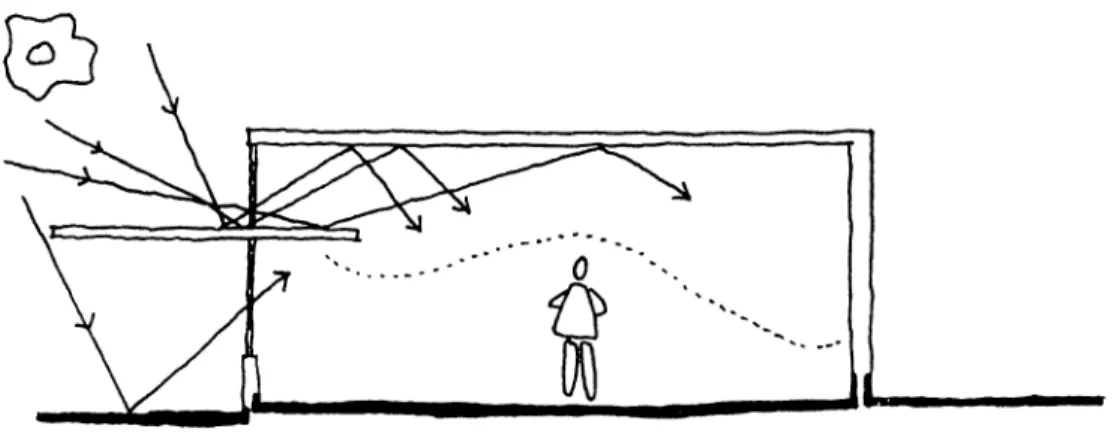
Luminances coming to a window from the sun and /or the sky can be much higher than other surfaces' luminances within the room. The intensity of illumination from direct sunlight on a clear day varies with the thickness of the air mass it passes through. It is less intense at sunrise and sunset. Direct sunlight illuminates normal (perpendicular) surfaces with approximately 60000 to 100000 lux, and this is too intense to be used directly for task illumination. So the luminances introduced at any opening from the sun or from the sky, can be much higher than the other surfaces' luminances within the room and that can cause several unwanted troubles like direct glare, reflected glare and veiling reflections (Steffy, 1990). As a result, most illuminating engineers prefer to exclude direct sunlight completely from interiors (Moore, 1985). On the other hand, the movement and sparkle associated with controlled shafts of sunlight add considerably to the visual variety and excitement of a space. Even where visual tasks are fixed in location and subject to direct glare, occupant controls, such as shades and blinds, are preferable to permanent exclusion of direct sunlight. In addition, when the glazing is south-facing and vertical, direct sunlight contributes favorably in winter to workers psychological condition because it evokes positive feelings related to its warmth and brightness as well as thermal comfort (Recommended Practice of Daylighting, 1979). As a result, the interest in using direct sunlight in buildings for both thermal and lighting purposes requires technical complexities.
In its passage through the earth's atmosphere, the light from the sun is scattered by dust and gaseous molecules of the air itself. As a result, sky appears to be more or less bright during the daylight hours, and becomes a major source of usable daylight illumination for building interiors. As compared to sun, the sky has a large visual area and relatively low luminance. The brightness of an overcast sky is approximately three times
as bright overhead as it is at the horizon and it provides diffuse light from the clouds and reflected light from the ground. The sky luminance on a clear day is approximately three times as bright as at the horizon than overhead. It consists of direct light from the sun, diffuse light from the sky and reflected light from the ground. A partly cloudy sky provides diffuse light from the ground and direct light from the sun (Recommended Practice of Daylighting, 1979).
When a matte reflective surface is illuminated by a primary source (sunlight or skylight), its resulting luminance makes it an indirect source of illumination. Because it is a distributed source, the quality and distribution of its light is virtually identical to direct sky light admitted through a similar sized opening. If directly sunlighted, white reflector luminance can be as high as approximately 17000 to 34000 cd/m^ substantially more than the luminance of the skydome as approximately 1700 to 7000 cd/m^ (Moore, 1985).
Color temperature of daylight is in the range of 4000 Kelvin to 10000 Kelvin. Overcast skies generally associated with low color temperature (4500-7000 Kelvin) and clear skies with high color temperature (10000 Kelvin and upwards). Sunlight has a color temperature in the range of 4000-5000 Kelvin.
3.1.1. Size, Shape and the Treatment of Light Source
The utilization of daylight is a function of fenestration and control mechanisms. Kaufman (1981) defined fenestration as: "any opening or arrangement of openings for the admission of light" (Kaufman cited in Moore,
1985). Walls and the roof could be used as areas for fenestration. The location of fenestration has an effect on the illumination quality and quantity. Regarding the placement of the openings, if the system intended to produce uniform brightness on an interior horizontal surface, moderate-sized openings should be placed so that the center to center spacing does exceed two times the height of the ceiling above the workplane (Flynn et.al., 1992). The size of the opening, characteristics of the glazing material, and control elements are the three important factors that determine the quantity of light admitted from an opening (Moore, 1985).
Windows are one of the daylight media which are used as a permanent way to control interior penetration of light, and they must be examined carefully. The importance of the view-giving properties of windows should not be underestimated. Many studies indicated that, there is a desire of contact with the outside world among the workers. A survey on the windowless offices in U.S. showed that among the reasons for disliking the windowless interior was the lack of daylight (Recommended Practice of Daylighting, 1979). However, a direct view of the sky can cause a feeling of discomfort (discomfort glare). To prevent this, excessive contrasts should be reduced by controlling the direct light sources such as window or skylight and by raising the luminance of the of surrounding surfaces of them. For example, a bright sky seen through a window in an under-lighted or darkly finished room is able to cause discomfort glare (Daylighting in Architecture, t993). Both large and small windows may appear very bright because of the relatively high luminance of the exterior environment. The high luminance area, as well as direct sunlight, can cause severe problems to VDT users. For this reason, means of shielding or controlling the light from windows are important in any area containing VDT's. Screening the window from VDT screens by adding free standing part-height partitions can be solution, and
these allow some adjustment in positioning while permitting some natural daylight to pass over the partition (CIBSE, Lighting Guide: Areas for Visual Display Terminals, 1989). Positioning window as high as possible (preferably 45 degrees or more above the horizontal) locates the offending brightness above the field of view. While high window locations reduce glare from high-brightness exterior areas, they increase the potential of deep
sunlight penetration, which can result in glare on interior surfaces.
Hopkinson (1966) stated that;
Daylight from the window in relation to the height of that window depends upon two things, first, that by the operation of the cosine law of illumination, light which reaches a reference plane at a small angle of incidence results in a higher illumination than that which reaches the plane from large angles of incidence, and second, the fact that with an overcast sky the zone near the horizon has the lowest luminance, and therefore the higher the window the brighter the sky which is seen through it (p.434).
It is clear that the higher the fenestration, the greater will be the illumination at a distant point. As a result, room depth, height and daylight quantity are closely related. The level of direct daylight decreases in a considerable manner, as the distance from the window increases. So, higher fenestration provides more uniform distribution than comparable lower locations and controls veiling reflections, while illuminating the vertical surfaces effectively (Moore, 1985). On the other hand, when the sky is too bright, there occurs a greater need to screen high windows than view windows. Hopkinson (1966) indicated that;
. . . for a work area, a ratio of 1:2 for the height of the window to the depth of the room from the window
usually gives an approach to the optimum daylight distribution (p.435).
Also, high v^indows (clerestories) can be designed together with the side windows like lightshelves (Figure 3.1). Lightselves are located as low as possible to the floor in order to reflect the most amount of light to the ceiling. The front back of the shelf must be large enough to shelter most area of the room during the sunny days. The reflectance of both inner and outer upper section should be high without specularly reflecting surfaces which creates visual hot spots on the ceiling. Matte surfaces work rather well. The bottom of their surfaces should be finished to balance the room's lighting.
Figure 3.1 Lightshelves.
The effectiveness of the side lighting is limited with a distance into the room away from the windows approximately two and a half times the height of the opening (Recommended Practice of Daylighting, 1979). If the total quantity of light brought into the room is assumed to remain the same, distribution of the fenestration over a large area will (1) reduce shadows, contrast, and texture definition, (2) provide more uniform light distribution, and (3) reduce veiling reflections (Moore, 1985). Strip glazing produces more uniform light
level across the room than the individual windows. The surface immediately surrounding the light source (window or skylight) is important in terms of glare. If the luminance of these areas could be kept within an intermediate luminance between the source and the general environment, such contrast differentiation will be helpful. Also the design of the window is an important issue in design. For example, using windows with splayed reveals (Figure 3.2) forms a "soft frame", and it may be helpful to soften the transition of light from the window glass to wall gradually rather than sharply (Daylighting in Architecture, 1993). Also, the sills of clerestory windows should be sloped downwards. However, if not, a deep sill can have a considerable result in reducing the effectiveness of a clerestory window (Hopkinson et.al., 1966).
Figure 3.2 Window with splayed reveals
A study which is conducted in 1982, dealt with the daylight as a source of discomfort glare. In this study, the skylight was taken as a reference and direct and reflected sunlight were neglected. The main conclusion of the study is that:
Discomfort glare from a single window (except for a rather small one) is practically independent on size and distance from the observer, but is critically
dependent on the sky luminance (Daylighting in Architecture, 1993, section 2.17).
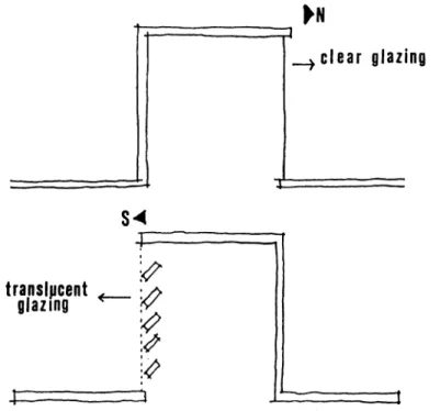
Monitors are also daylight media. They are the roof structures that utilize vertical or steeply sloped glazing which allows for the contribution of roof- reflected light and (in the case of south oriented glazing) more direct exposure to winter sunlight (Moore, 1985). North-facing monitors provide the opportunity for daylighting without sun controls and can use clear glazing for maximum transmission since diffusion is inherent in the sky light. Whereas, south-facing monitors have to use translucent glass or white baffles to diffuse direct sunlight (Figure 3.3). In the case of a sawtooth slope monitors (Figure 3.4), when the slope is greater than 45 degrees, the average illuminance is constant, in spite of the increased vertical glazing area. Mazria (1981) described a south monitor with vertical glazing combined with an overhang and interior vertical baffles spaced to shield all direct sunlight. This monitor provides a very high illumination immediately below, with a rapid fall-off at the perimeter (Figure 3.5) (Mazria cited in Moore, 1985).
Figure 3.4 Sawtooth monitor.
non- non·
D A Y L I C H T I N C
Figure 3.5 Monitor with vertical glazing combined with an overhang (Moore, 1985, p.85).
Admitting daylight through east and west monitors poses a distribution problem because of a daily sun movement problem (Moore, 1985). Most conventional skylight fenestration does not extend below the ceiling plane. Hence the ceiling contributes little to daylight distribution since it is not receiving any direct light transmitted by the skylight (Moore, 1985). To project a translucent skylight diffuser below the ceiling line refracts light onto the ceiling directly, utilizing its reflectance (Figure 3.6). As a result, while ceiling luminance increases, brightness contrast with the skylight itself will tend to reduce.
r
Figure 3.6 Skylight below ceiling plane
The uneven distribution of illuminance typical with flat, translucent skylights (Figure 3.7) can be improved with sloped reflectors (Figure 3.8), which reflect transmitted light back onto the ceiling surrounding and block out direct light to the room directly below, while allowing light to penetrate directly to the perimeter of the room ( Moore, 1985).
Figure 3.7 A typical flat, translucent skylight.
Figure 3.8 Skylight with a sloped reflectors below ceiling plane.
A sloped skylight-well (Figure 3.9) diffuses light admitted through a small roof opening over a larger area before entering the room (Moore, 1985). If clear glazing is used, the sides of the well can shield sunlight from entering the room directly, diffusing it by multiple white-wall reflection (Moore, 1985).
Figure 3.9 A sloped skylight well
Daylighting can be designed as a combination of side-wall fenestration in opposite walls, or a combination of side-wall lighting and toplighting or as a bilateral lighting (Figure 3.10).
\
bilateral lighting, (c) side and skylight lighting.
In general, people using committee rooms are in the need of having some natural lighting. The occupants in a side-lighted committee room can be
faced with different forms of discomfort. Members facing a window may be suffered from glare, and the others seated opposite to them seen in a shadow silhouetted against the bright sky. Also, those having backs to window may cast a shadow on their own papers. So glare from the window should be prevented. This could be achieved by attenuating the light gradient from the window to wall gradually with splayed revealed windows, while using shading devices in interior or exterior, such as baffles or a Venetian blinds, as an elements to control direct sunlight entrance. It is highly advisable that the pinboards and flip charts should never be placed next to a window. Although discomfort glare is acceptable, the disability glare will make them harder to read by impairing the vision. Also, they should be placed where there is no possibility for them to reflect a shiny image of the window (CIBSE, Lighting Guide: The visual Environment in Lecture, Teaching and Conference rooms, 1991).
Today, most of the new buildings are using electric lighting systems in conjunction with daylight to light interior areas adequately. Electric light and daylight are compatible and complementary sources, and can be used to produce optimum results in interiors (Figure 3.11)
Figure 3.11 Examples o f combined system (Daylight and electric lighting).
3.1.2. Control Methods
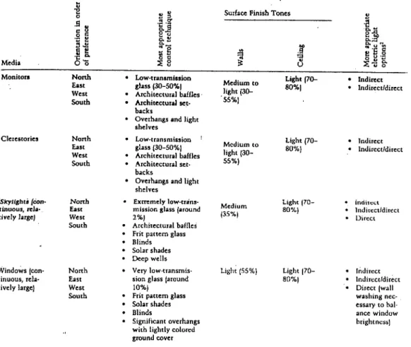
By control it is meant the control of the intensity and the distribution of daylight in the space. Distribution is affected by the size, shape, location and the orientation of the windows and skylight, and glazing materials. Intensity is controlled by glazing and control devices, such as blinds, drapes, louvers, etc. Other items that affect daylight distribution and intensity are exterior objects such as trees and other buildings, ground reflectances, overhangs and awnings, and interior finishes and configurations. Daylight media (monitors, clerestories, skylights, windows) with appropriate orientation, shading control and room surface finishes along with proper electric lighting is necessary to achieve cost-and occupant- effective daylighting (Steffy, 1990). Many workspaces today involve reading and electronic-based tasks such as VDT's, so daylight quality and quantity requirements differ from the requirements of the recent past. As a result, there arouse a need of controlling the daylight media with appropriate glass and shading, as well as controlling room surface finishes and electric lighting with great care. The daylight media and most appropriate control techniques that might be used in workplaces is summarized in Table 3.1 (Steffy, 1990). The orientation for daylight media depends on the geographic and topographic location. Generally, the more diffuse the daylight is, the less bulky the control technique and the more uniform the brightness of the daylight media (Steffy, 1990). Caution is advised when using daylighting in offices where there are computer screens; direct light creates too many reflections on screens and, even with indirect daylighting, ambient light levels must not be very high (Kleeman et.al., 1991). Brightness uniformity and brightness limits are critical if glare and VDT imaging problems are to be minimized. Nevertheless, diffuse north skylight luminances can still
exceed approximately 10000 cd/m^, which is more than ten times the luminance limits set for indirect lighting by the Illuminating Engineering Society (lES) VDT Guidelines, and therefore, shade control techniques are advisable even for north-oriented daylight media (Stefly, 1990).
Table 3.1. Daylight media for workspaces (Steffy, 1990, p.78).
Media *2 0 4-» 3
II
Surface F in ish T o n e s V ■a g ^t jii
- aill
0 0 •5? 0 •c u ^ u < jy Ok 0 Monitors Clerestories ^'Skylights (con tinuous, rela·. tively large) Windows (con tinuous, rela tively large) North East West South North East West South North East West South North East West South Low-transmission glass (30-50%) Architectural baffles Architectural set backsOverhangs and light shelves Low-transmission ' glass (30-50%) Architectural baffles Architectural set backs
Overhangs and light shelves
Extremely low-trans mission glass (around 2% )
Architectural baffles Frit pattern glass Blinds Solar shades Deep wells Very low-transmis sion glass (around 10% )
Frit pattern glass Solar shades Blinds
Significant overhangs with lightly colored ground cover Medium to light (30-■55%) Medium to light (30- 55%) Medium (35%) Light (70- 80%) Light (70- 80%) Light (70- 80%) Light (55%) Light (70-80%) Indirect Indirect/direct Indirect Indircct/direct indiicct Indirect/direct Direct Indirect Indirect/direct Direct (wall washing nec essary to bal ance window brightness)
Roof overhangs and window-shading projections can be designed to shield windows from direct sunlight while allowing some skylight entrance. The control techniques exist for either interior or exterior applications, on windows and skylights. Control elements applied to the exterior of buildings are effective from the heat control standpoint. Such elements transmit most of the absorbed heat to the exterior air. However, they can require adequate
maintenance as they are revealed to weather and pollution. On the other hand, interior elements are less susceptible to pollution, whereas they tend to absorb and reradiate heat to the interior influencing both the occupants' comfort and the air conditioning load (Recommended Practice of Daylighting, 1979). Usage of low-transmission glass, usually tinted gray or bronze, or solar shades are effective for sunlight control (Steffy, 1990).
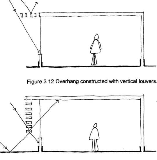
Overhangs can be used to diffuse light in two ways. The overhang material itself can be translucent (for example, a white fabric awning), or it can be consisted of series of parallel, opaque white louvers that provide shielding between critical solar angles (Figure 3.12, 3.13). This diffuses ail sunlight and most skylight by double reflection before reaching the glazing plane.
Figure 3.12 Overhang constructed with vertical louvers.
Low-transmission glass allows a clear view of the outdoors, but at the same time, usually changes the color of the view and of the incoming daylight. With gray tinted glass, the exterior view appears grayed and dull, and the sky always looks like cloudy. On the other hand, bronze- tinted glass, while distorting colors seems much more acceptable. It makes the exterior scene looks rather rosy, and incoming light has a warmer color. Newer, low- emissivity (Low-E) glass provides an improved-color view of the exterior and improved-color incoming daylight.
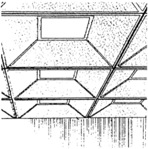
Recently, frit pattern glass usage is showing an increase in the market. Frit is a ceramic coating that actually is part of a glass and thus is permanent. The frit patterns can vary significantly from dot patterns to horizontal lines reminiscent of Venetian blinds, and it still has the ability of preserving the image beyond the glass. Charles Linn (1991) states about an example of the usage of frit pattern glass by the lighting designer Garry Steffy, in the design of an office building where the majority of floor space is devoted to open offices, and the VDTs are used extensively. The view requirement was given as a must to lighting designers, hence they were concerned about glare and over lighting from the sloped glazed windows. It's purely an electronic office; everyone in the space has at least one VDT, and some people have two (Figure. 3.14). Steffy says "decreasing the transitive value of the glass was a partial solution", and adds," although the problem might have been solved using louvers or some other interior or exterior movable shading system, Steelcase representatives wanted to avoid the maintenance headaches often associated with such devices. So, frit coated glass was used" (Steffy quoted in Linn, 1991). The appropriate usage of frit color is also very important. When light strikes translucent white frit, it diffuses, and if the source of the light is bright, the translucent white frit can be a source of
serious glare. Linn (1991) describes Steffy's solution for an open-planned office building:
This was solved by applying light gray frit on the glass so that it faced the interior of the space, and applying black frit behind it. As a result the frit essentially becomes opaque to the sun's rays, and no longer diffuses the light striking it (p.26).
This method also may allow to uplight glass. A skylight designed with the light gray frit pattern glass could be uplight with fluorescent luminaires. With this system, it is possible to avoid too extreme luminance contrast and also to provide additional ambient lighting on cloudy days and a during the working hours after dark. Because, normally you can not uplight an ordinary skylight since the light would go through the glass and all you could see is a reflection of the lamp (Linn, 1991).
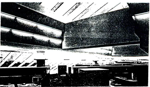
Figure 3.14 Skylight and the loft system of the open-automated office (Steffy, 1990, p.113).
Fixed exterior shading devices such as fins (Figure 3.15), or various types of shade-screen materials are often employed. They shade the window from direct sun penetration but allow the diffuse skylight transmission. Operable shading systems let dynamic control to supply improved thermal and visual comfort, and they work suitably on the west and east elevations (Johnson, 1986). They are generally motor-driven and controlled by photocell, and require cleaning periodically. Low-transmission glass, frit pattern glass, and photocell-controlled shades are very appropriate daylight control techniques for very large areas used by many people (Steffy, 1990).
Figure 3.15 Plans of various types of fins (Olgyay & Olgyay, 1957, p.91)
On the contrary, more independently controlled smaller-scale daylight control techniques such as horizontal or vertical blinds and drapes can be very problematic for large areas used by many individuals. A horizontal blind properly set for one person may cause severe VDT imaging problems for someone working nearby. A vertical blind set properly for one side of a room is inevitably set improperly for the other side, unless set in the closed position. Once the drape is opened just a little bit, there might arise a potential for serious glare and VDT imaging problems. Hence, it is advised to use these two techniques for single occupancy rooms (Steffy, 1990). Also,
there is the possibility of placing intermediate screens between the VDT workstation and bright windows. Such a screen should not have reflectance higher than about 50% (Grandjean, 1987). Photocell light sensors and dimmers in conjunction with a programmed computer are usually utilized in systems using daylight as a major component (Kleeman et.al., 1991).
Where daylight media are used extensively in workspaces, finishes of wall and ceiling surfaces should be matte in order avoid harsh, glary reflections of light. The walls should have minimum reflectance of 30 percent, and the ceilings should have a minimum reflectance of 70 percent. These reflectances allow the daylight to inter reflect within the room, providing more efficient use of light source.
For the control of daylight in committee room, one approach is to ensure that the chairman faces the window and can control both the curtains and the electric lighting and this arrangement makes the chairman's face is clearly revealed, that there is no visual discomfort, and the faces of other participants can be seen comfortably (CIBSE, Lighting Guide: The Visual Environment in Lecture, Teaching and Conference rooms, 1991). However, it is stated that in this situation the others will have some trouble in seeing one or another.
3.2. Artificial Lighting of Open-Automated Offices
Perhaps, lighting of an open automated office is the most questionable and least resolved problem. According to Fisher (1986), it is not just the
unpredictable location of desks in open offices that makes their lighting problematic, but also the variety and difficulty of the seeing tasks (reading of a computer screen) that are performed there adds considerable to the problem. Existence of veiling reflections on the screen produced by office lighting system makes the seeing task much more difficult to perform. Therefore, the type of lighting system becomes very important. Today direct, indirect or combination of both systems can be used according to the requirements of the spaces. Each of them have both advantages and drawbacks, and differs in their methods of light distribution, light control, and overall appearance.
3.2.1. Direct Lighting
In a direct lighting system, light comes from its source to work space without first being reflected from other room surfaces. Direct lighting is the most commonly used system for offices, and is often applied as a blanket solution, using a grid or row pattern throughout the entire ceiling of an office (Harris et.al.,1991). This system provides equal levels of illumination across large spaces, which is necessary when activity or task location within space is unknown. So, this system emphasizes the ceiling surface and emphasizes work surfaces and floor surfaces.
Task-oriented approach is another application of direct lighting. With this method proper illumination is provided by locating the fixtures only over the work areas. Other areas such as corridors, reception areas, and lobbies, are illuminated to a lower illumination level. Task oriented lighting is a direct response to a need for optimum lighting and energy conservation. A recent
application of direct lighting is the system developed for use with high amounts of VDTs in the workplace. With this application, a uniform pattern of a low level of uniform illumination throughout the space (approximately 160-300 lux) which provides illumination for traffic and large, non-critical tasks (Harris et.al.,1991). Task lighting is installed at each workstation in order to provide necessary illumination for local task, and this brings the optimum user comfort and productivity.
Using downlighters means that the luminaires will be ceiling mounted or suspended close to the ceiling. So, the ceiling above and behind a VDT operator normally composes the major part of the area reflected in the screen. To select luminaires with the correct intensity distribution is very important in order to avoid high luminance images appearing on the screen. However, only selection of the correct luminaire is not enough, also sharp contrasts within the interior should be avoided. Therefore it is necessary for the designer to have some influence over the control of daylighting and working plane and wall reflectivity (CIBSE Lighting Guide: Areas for Visual Display Terminals, 1989). Since, in the case of direct lighting, very distracting luminances may be created, low brightness ceiling luminaires are usually chosen to reduce the potential for veiling reflections on the VDT. High luminance reflections on a VDT can be controlled by limiting the luminances of luminaires in appropriate directions because these reflections are a matter of geometry (Figure 3.16). The solution described as:
If the VDT is assumed to be standing on a desk, viewed by someone sitting in front of it, then limiting luminance of the luminaire above the angle of view from the screen will also limit the luminance of reflections on the screen: the lower the luminance
above this angle, the lower the luminance of the screen reflections(Lighting Guide: Areas for Visual Display Terminals, 1989, p.7).
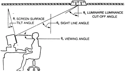
Figure 3.16 Typical geometry for eye, screen and luminaire (Florence, 1992, p.33).
By examining the geometric relationship of the eye, the VDT and a typical ceiling luminaire, the sight line angle or the luminance limitation angle can be calculated (fig 3.16). Noel Florence (1992) explains this relation as:
The relationship involves the viewing angle from the eye to the VDT, Qt, and the screen surface tilt angle, Qt, which together control the sight line angle, Qs, and relationship is Qs = Qv + 90 - 2Qt (p.32).
Noel Florence (1992) states that there are 25 luminance limitation angles (angle of sight-line) calculated with the help of 5 realistic viewing and screen tilt angles (Table 3.2).
Table 3.2 Screen to ceiling luminance limitation angle (angle of sight-line) from the vertical (Os) in degrees.
Veiwing Angle (Q v) (degrees)
Screen Tilt Angles (Q t)
0 5 10 15 20 90 80 70 60 50 95 85 75 65 55 100 90 80 70 60 105 95 85 75 65 110 100 90 80 70 0 5 10 15 20
From the Table 3.2 it can be seen that there are only two cases in which sight-line angle is 55 degrees or less and only four cases where it is 65 degrees or less (This recommendations related with positive contrast screen having luminous letters on dark background). So, Lighting Guide published by CIBSE (1992) categorized the luminaires as:
The luminaires are referred the Category 1, 2 or 3. These have luminance limitation above 55 degree, 65 degree and 75 degree to downward vertical respectively. The angles do both infer " cut off " angles but rather sharp run back on the polar curve in all vertical planes. Above these angles the average luminance does not exceed 200 cd/m^ (p.11).
If a luminaire had no luminance at 55 degrees or greater, its reflection would hardly ever been seen in the VDT regardless of where it was placed on the ceiling and if it had no luminance at 65 degrees or greater, it would seldom be seen (Florence, 1992). It is advised that more critical the VDT application, or the higher the VDT density in an area then, in general, the lower this angle (luminance limiting angle or sight-line angle) (CIBSE Lighting Guide:
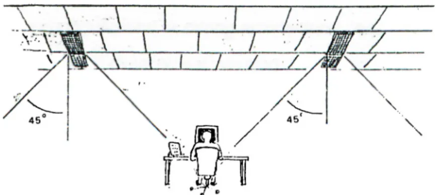
Areas for Visual Display Terminals, 1989). While the angle gets lower then the efficiency of the luminaire also tends to get lower, due to the much better control of the luminaire's distribution. Thus it is preferable to install the light fixtures parallel to and on either side of the operator. Luminance flux angle should not exceed 45 degree to the vertical (Figure 3.17) ( Grandjean, 1987).
Figure 3.17 Ceiling lighting generating a cone of light with an angle of 45 degree to the vertical (Grandjean, 1987, p.53).
The layout of the perimeter spacing of luminaires and their proximity to walls and columns are very important points needed attention. This is because the luminaires can produce bright scallops on surfaces that they close to (especially likely at the ends of a luminaire). In order to avoid sharp transition from high luminance of the scallop to the lower luminance adjacent, it may be preferable to keep luminaires set back from walls - even if this means offsetting them from a regular array. The careful use of asymmetric luminaires to assist as wall washers could be another approach, because even illumination with slow rate of change is preferable to uncontrolled scalloping. However, it is possible that dimming control will be