Organised
by the Institution of
Engineering
and
Technology
Radar, Sonar and Navigation Network
The Knowledge Network
Range
Resolution Improvement
in
Passive
Coherent Location Radar
Systems using
Multiple
FM
Radio
Channels
A
Sinan
Tasdelen
& H
Kbymen,
Bilkent
University,
Turkey
©)The
Institution
of
Engineering and Technology
Printed and
published by
theIET,
MichaelFaraday House,
Six HillsWay,Abstract
With the improvement in
digital signal processor technology, the topic of Passive
Coherent
Location
(PCL)
radar systems that
exploit
'illuminators of
opportunity'
became a
popular area
of research.
Comparative
studies
of
Ambiguity
function
properties of
broadcast
signals such
as
FM
radio, analogue television,
cellular
phone signals
and
digital
audio
broadcast (DAB)
revealed that FM radio broadcast
signals, providing
up
to
30dB
peak to side lobe levels in range, and up
to
40dB
peak
to
side lobe levels in
Doppler, are
well suited for passive
radar purposes.
However, due
to
low
modulation bandwidth
in
FM,
which
never
reaches
the allowable
channel bandwidth
of 150
kHz, the
range
resolution is
severely
limited. While
150
kHz
modulation
bandwidth
can
provide
lkm
range
resolution,
at
best,
30
kHz modulation
bandwidth is
achieved,
which results in 5km range resolution.
Furthermore,
the
modulation bandwidth is
strongly
dependent
on
the content that is
being
broadcasted.
An
improvement
in range
resolution is obtained
by using multiple adjacent
FM
channels,
emitted
from co
sited
transmitters,
which is often the
case
in
large
towns
in
countries,
where the FM channel allocations
are
weakly regulated.
A
number of channels
can
be used
independently
or
together. When
channels
are
used
together
the
range resolution is
dominated
by
the total
channel bandwidth. The
auto
ambiguity
function of
multiple
channel FM
signals
shows
high
side lobes. Once the range is estimated
using
a
single
FM
signal, it
can
be refined
by
using
more
FM
channels
subsequently.
The number and
locations of the FM
channels
that
will be
used
in
the
PCL process
can
either be
predetermined or chosen at each
recording separately, taking
into account
the power and
modulation bandwidth of
each
channel.
A new
scheme is
proposed, which takes
multiple
FM
radio channels emitted
from co sited
radio transmitters.
Again two receiver antennas are used: One for direct signal reception and one for the
target scattered
signal reception. The direct signal is used in the computation of the
autocorrelation
function of the FM waveform. The signals from both antennas are used in
that down to -30dB signal to noise ratio (SNR) the autocorrelation function of 7 adjacent
FM
channels with random content can be
successfully extracted
from the cross
ambiguity
function. Hence, the range resolution is significantly improved. Best results are achieved
when all channels have
equal
power. For
sufficiently large
SNR,
the cross
ambiguity
function for
multi FM
channel
waveform has an
envelope
similar to
the
cross
ambiguity
function a
singular
FM
channel waveform.
Range
resolution can be
improved
down to 180
meters when 7
adjacent
FM
channels are used together.
Range
Resolution
Improvement
in
Passive
Coherent Location
Radar Systems Using Multiple
FM
Radio
Channels
A.S. TaEdelen, H. Koymen
Department of Electrical and Electronics EngineeringatBilkentUniversity, Ankara, Turkey [email protected], koymen @ee.bilkent.edu.tr
Keywords: Passive coherent location (PCL),rangeresolution,
modulationbandwidth,FMradio,cross-ambiguity
Abstract
Passive coherent location (PCL) radar systemsthatuse single
FM radio channel signal as illuminator of opportunity have
limited range resolution due to low modulation bandwidth
andhigh dependence on the content that is beingbroadcasted
from the FM station. An improvementin range resolution is
obtained by using multiple adjacent FM channels, emitted from co-sited transmitters, which is often the case in large towns in countries, where the FM channel allocations are
relatively weakly regulated. The proposed scheme computes
the autocorrelation function of the signal directly received from the FM co-located transmitter, and compares it to the
cross-ambiguity function, obtained from direct and target scattered signals. The geometry ofthe problem is like in the case of monostatic radar. The range information is obtained by the delay between the cross-ambiguity function and the
autocorrelation function. It is shown that down to -37dB
signal
to noise ratio (SNR) the autocorrelation function of 7FM channels with different contents can be successfully extracted from thecross-ambiguity function. The detection of the time delays is a linear estimation problem. The issue of
time-delay estimation is a known topic of research. A
powerful estimatorcanbefound.
1
Introduction
The recent improvement in digital signal processor
technology made the topic of Passive Coherent Location
(PCL)radar systems thatexploit 'illuminators of opportunity'
apopularareaofresearch,again.
Comparative studies of Ambiguity function properties of broadcast signals such as FM radio, analogue television, cellular phone signals and
digital
audio broadcast(DAB)
revealed that FM radio broadcast signals,
providing
up to30dB
peak
to sideloberatio inrange,andupto40dBpeak
toside lobe ratio in Doppler, are well suited for
passive
radarpurposes [1, 2].
modulationbandwidth depends strongly on the content that is
being broadcasted from that station. It is reported that the bandwidth is seen to vary between 500 Hz and 22.2 kHz,
wherehighest bandwidth is obtained when fast tempojazz is
played as content. The range resolutions obtainedfrom these
signals is inthe rangeof 6757meters to 300km.
FM radio based PCL radar systems are shown to detect and
tracktargets to ranges up to 150 km from the receiver [3].
2
Using Multiple FM Radio Channels
The range resolution in radar systems is inversely proportional to the bandwidth of the waveform that is being used. This relation suggests that range resolution in PCL systems that use FM radio broadcast as 'illuminator of
opportunity' can be improved by increasing the total
modulation bandwidth of the waveform. Thiscan be doneby
making use of the signals of as many channels as required to achieve the aimed range resolution.
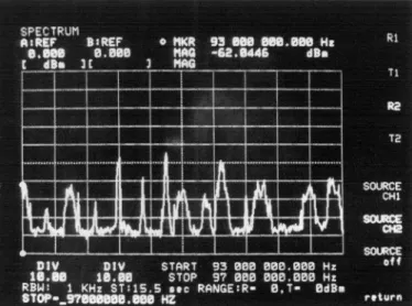
Figure
1: Part ofFM
frequency spectrumrecorded atBilkentUniversity, Ankara. Signals are transmitted from
-aldagi,
Ankara
Unlike in analogue TV broadcast signals, where the
service area, the carriers are separated at leastby300 kHz. In countries, where the FM radio channel allocations are weakly regulated, the maximum frequency deviation of the channels are faintly controlled, and frequencies that fall into the
adjacent channel are not adequately suppressed, causing in metropolitan towns spectrum readings as seen in Figure .
Interferences between adjacent channels, as seen in Figure 1,
although not desired in telecommunication, are beneficial for the proposed system. For instance, in Figure
1,
the whole94.7-95.6 MHz spectrum or 96.5-97 MHz spectrum can be
made use of, which has larger bandwidth than a single FM
channel, yielding asmallerrange resolution.
2.1 Ambiguity function of single and multi-channel FM
Waveforms
The radar ambiguity function is a long used measure in
evaluating the performance of a waveform in radar
applications. It represents the output of a matched filter [5],
andisgiven by the expression
oo
~~~~~~~~~~~~2
00
A=,
)
Js(t)s'(t+r)exp(j2ivt)dt (1)where A(r,V) is the ambiguity response at delay T and
Doppler uands(t) is thesignal under consideration. It canbe shown thatthe ambiguityfunction hasapeak at(0,0) and the
extentofthispeakindelay (orrange)andDopplerdetermines
the range and Doppler resolutions respectively [6]. It can be
shown that this peak isa global maximum for the ambiguity function. When o=0 ambiguity function reduces to the
autocorrelation function.
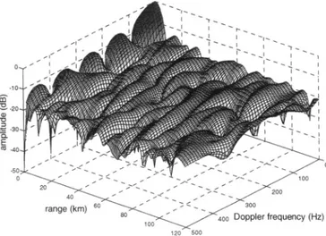
The ambiguity function of a frequency modulated signal is
given in Figure2. Since the ambiguity function is symmetric
for this signal, onlyaquarter isplotted.Themessagesignal is
a 15 kHz filtered monophonic music file of 100 msec in
length. The FMsignal hasamaximumfrequencydeviation of
+75 kHz withnopre-emphasis.
The Doppler resolution is a function of integration time,
meaning that it can be improved with longer recordings.
However, range resolution of this waveform cannot be
improved without changing its bandwidth or waveshape,
which isnotpossibleinPCL applications.
The ambiguity function of the signal containing three adjacent
FM channels, having different monophonic contents and
having 100 kHz equally spaced carrier frequencies, is
depicted in Figure 3. It is observed that the ambiguity function of the signal containing a single FM channel is an
envelopetotheambiguityfunction of three FM station signal.
Figure 2. Ambituity function of single FM channel signal
40'-- /300
CL ~60 - < '
E ~ ~ rne(m 0 - 0
range
(km)5G
Dopplerfrequency (Hz)Figure 3. Ambiguity function of 3 adjacent FM channels
signal
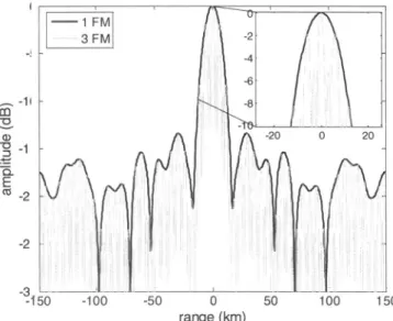
Therangeresolution obtained by using onlyoneFMchannel,
andtherangeresolution obtained from three adjacent stations
that broadcast differentcontent aredepictedin Figure4. Both
signals havemessagecontentswith similar bandwidth. The envelope of the autocorrelation function for three
adjacent FM stations is the autocorrelation function for a
single FM station. This isdue to thefact that the spectrum of
three adjacent FM station signals is almost like a 100 kHz
repetition of a single FM station spectrum. Due to the
periodic structure in the spectrum, a sinc type formation is
observed in the range resolution plot. Since the modulation
bandwidth is about three times the bandwidth ofa single FM
transmission, the peak in the autocorrelation function is
narrower. -10-a : -20 a) '0 -30 -E CZ A40V
-10 m a) 0 -15-E co -9f -3
-?50
-100 -50 0 50 100 150 range(km)Figure 4. Autocorrelation functions of single FM channel waveform and threeadjacentFMchannels waveform
Thepeakcanbe madenarrower when seven adjacent stations
areusedtogether(Figure 5).
range(km)
Figure 5. Autocorrelation function for stations
seven adjacent FM
As in the three FM station case, the shape of the
autocorrelation function ofthewaveformfrom seven adjacent
FM stationsresembles the autocorrelation plotofasingleFM
transmission. However some side-lobes areincreased. Again,
asinctypeformationis observed in therangeresolutionplot.
Ifstations are selected in arandom way so that they are not
adjacent, then the autocorrelation starts to lose its
resemblance to the autocorrelation function of a single FM waveform. The autocorrelation function ofseven FMsignals
having equal power, but distributed randomly in 1500 kHz bandwidth with minimum
separation
of 150 kHz and maximumseparation250 kHz isdepictedinFigure6.m a1) 3 E CZ
-S50
-100 -50 0 50 100 150 range (km)Figure 6.Autocorrelationfunction for seven non-adjacent FM stations
As
expected,
the sinc type formation in the range resolution is lost due to the failed periodicity and the side-lobes in thevicinity ofthe peak areincreased. However, the main peak is
still narrow. Theoretically, the range resolution can be improved down to 2 km with an appropriate detection
algorithm.
2.2 Minimum SNR Criterion
In the analysis of the auto-ambiguity and autocorrelation functions the scatteredsignal is assumed to be noise free. As the received power of the scattered signal becomes smaller, the SNR decreases for far away targets. Consequently, the
ambiguity function deteriorates, yielding a worse range resolution or even target loss orfalse alarm.
The proposed detection method depends on the minimum
SNR that allows a successful detection ofthe autocorrelation
function, buried in the cross-correlation. This is discussed in Section 3 of this paper.
In the following simulations, the receiver noise is taken as white and Gaussian distributed, with spectral height of
kTOB,
where k is the Boltzmann constant,
To
is the temperature in Kelvin (taken as 300'K ) and B is the bandwidth. Thebandwidth is200 kHz in single FMsignal simulationand 800
kHz in seven FM signals simulation, where the carriers are
spaced atmultiples of 100 kHz, and signal powersare equal.
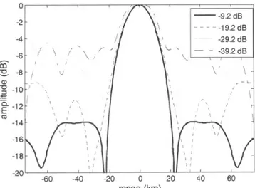
Thesignalsare sampledat 5 MHz. Simulations show that for
a singleFM signal, the autocorrelation function preserves its
shape down to -19dB SNR. For lower SNR the
cross-correlation termsbetween signal and noise start todominate. However, thepeakofthe autocorrelation is dominant downto
-29dB as shown in Figure 6. If the number of FM signals is increased, the autocorrelation shape shows novariation down
side---9.2 dB -19.2 dB -4 -29.2dB -6k
~~~~~~~~~~~~-39.2
dB 14 16 18 -r_v -60 -40 -20 0 20 40 60 range (km)Figure 7. Autocorrelation function for single FM signal for various SNR
4
Detection
In [7] it is shownthatthe Dopplerresolution ofaPCL system,
using FM radio broadcast as non-cooperative illuminator, is
typically 1 Hz, corresponding to a velocity resolution of
around 1.5 ms'. The Doppler resolution canbe improved by
taking a longer integration time. In the analysis below it is
assumed that the Doppler shift ofthe target is found by the
radar and the signal is perfectly corrected in frequency. Assume s(t) is broadcasted from a FM radio transmitter and
received from aco-located receiver. This direct signal, s(t)at
the receiver has a high SNR. The signal reflected from N targetsand receivedfrom thereceiver isrepresented by
N
SN
(t)
=)a
is(t
-ti
)
+n(t)
i=l
(2)
where ci is the attenuation constant for the signal scattered from the ith target. t- is the two-way time delay of the signal
scattered from the ith target and n(t) is the zero mean white Gaussian noise process. The result of thecross-correlation of direct andtarget scattered signalsis givenby
N
C(r)=
Lai
R(r-ti)
+ns(r)i.=}
-60 -40 -20 0 20 40 60
range(km)
Figure 8. Autocorrelation function for seven adjacent FM
signalsfor various SNR
m
a1) CD
E
.C_
where A is the autocorrelation of the direct signal and ns is
thecross-correlation of the direct signal and noise. Takingthe
Fourier transform of thecross-correlationfunction, weobtain
N
C(f) = Za
exp(-j2?7t
)F{R(r)}+N,S(f) (4)where F{R(T)} is the Fourier transform of the autocorrelation function , No is the power spectral density ofthe white noise
andS(f)is the Fourier transform of the direct signal. Dividing both sides by A(f) and applying the autocorrelation property
of the Fourier transformweobtain
C(f) N0S(-
foi
t)
Zaexp(-j2fti
) + Za.exp(-j24zt.)+
t1= S(f) (5) (6) -20 -15 -10 -5 0 5 range(km)Figure 9. Autocorrelation function for
signals for various SNR(zoomed)
where * denotes the complex conjugation. The problem
ILL LJAJLl . , reduces to finding the timeshifts tiinthe exponential. This is
10 15 20 a linear estimation problem, and very good estimators are
available. In the estimation problem for single channel FM
seven adjacent FM signal, the estimation is done around one frequency, whose
width determines the range resolution. The SNR around this
frequency is higher than in other frequencies. If, for instance, 3 FM channels are used. the estimation can be done around
m a) .0 . :t--2~
-4r
-61 -10 -6.8 dB l-16.8dB -26.8dB -36.8dB . ,, ,3.dB co -'a E CZ -12 I -e I~~~~~~~~~~~I(3)
three frequencies, which implies that the range resolution is
improved. The total signal power increases, but due to the additional bandwidth thenoisepowerincreases too. Thetotal
SNR, therefore, does not change. This results in the same
detectionperformance as in the single FM channel case.
5
Conclusions
In this paper, we have shown that by using multiple FM broadcast channels as the 'illuminator of opportunity' for a
PCLradar system, the rangeresolution, which is in the order
of 6-7 km for highest modulation bandwidth measurements for single channel FM transmission, can theoretically be improved down to 1 km with seven channel FM signals. The
estimation around multiple frequencies suggests that the range resolution can actually be further improved. The minimum SNR criterion in the finding of the autocorrelation
function in the cross-correlation is important. For low SNR
this issuebecomesproblematic.
We will handle the issue of an optimum detection and
location algorithm, which finds the time shifts
t1
in equation(6), as a future work. We will test efficient algorithms for time delayestimationlike in [8]fortheirperformance. We will also evaluate the performance of
first-detect-then-locate algorithms that use single FM channel signal for fast target detection, and multiple FM channel signals for finer
localization of a target and/or distinction of multiple close
targets.
We will investigate the Bi-static nature of the problem as a future work.
6
References
[1]
H.D. Griffiths, C.J. Baker. "Passive coherentlocation radar systems. Part 1: Performance
prediction",IEE Proc., Radar SonarNavig., 152,pp.
153-159, (2005).
[2] C.J. Baker, H.D. Griffiths, I.
Papoutsis.
"Passive
coherent location radar systems. Part 2: Waveform properties",IEE Proc., Radar SonarNavig., 152, pp.
160-168, (2005).
[3] P.E. Howland, D. Maksimiuk, G. Reitsma. "FM
radio based bistatic radar", IEE Proc., Radar Sonar
Navig., 152,pp. 107-115, (2005).
[4] P.E. Howland. "Target
tracking using
television-basedbistaticradar", IEEProc.,
Radar
Soniar
Navig.,146, pp. 166-174, (1999).
[5]
B.R. Mahafza. 'Radar systems analysis and designusing
MATLAB', (Chapman & Hall/CRC, 2000), Chap6.[6]
N. Levanon, E. Mozeson. 'Radar Signals', (JohnWiley & Sons, 2004),Chap.3.
[7]
P.E. Howland, D. Maksimiuk, G. Reitsma. "FM radio based bistatic radar", IEEProc., Radar-
Soniar
Navig., 152,pp. 107-115, (2005).[8]
J. Li, R. Wu, "An efficient algorithm for time delayestimation",IEEE Trans. Signal