loxh Int. Conf. on Mathematical Methods in Electromagnetic Theory
Sept. 14-17, 2004. Dniepropetrovsk, Ukraine
MM.&T*O4
..
,.LARGE FLAT PLATE
MODELS
IN
THE
PHYSICAL OPTICS METHOD FOR RCS CALCULATIONS
Ayhan Altintas, Aslihan Celik Bilkent University Ankara, TURKEY
E-mail: [email protected], [email protected]
Absfracf
-
The calculation of Radar Cross Section (RCS) of arbitrarily large perfectly conducting body is presented. The body is modelled as triangular meshes of any size by the help of graphical tools. For the calculation of scattered field, Physical Optics(P0) surface integral is analytically evaluated over each of the triangular meshes. Due to the analytical integration, there is no limitation on the size of the triangles.I. INTRODUCTION
For Radar Cross Section (RCS) calculations of large objects, one needs to apply high frequency methods. One of the most common and simple approach is the physical optics(P0)[1,2]. Even though the PO approach is simple, for complicated targets for which there are no simple analytical expressions for the body shape, the body is modeled as flat plate meshes. Then, the scattered field from each plate is superposed to find the total field. Here, we concentrate on the triangular flat plate meshes, and it is shown that the PO approximation for the scattered field of the triangular meshes can be obtained analytically. Therefore, arbitrarily large-sized plates can be used in the mesh model. This approach yields very efficient calculations for objects composed of large flat facets, such as ships, buildings, etc.
As an example, RCS calculations are done on the triangular mesh model of fuel tank of F16 airplanes. Induced currents for different look angles are also computed with PO and presented for the fuel tank model.
11. GEOMETRIC MODELLING
The scattered field from a triangular plate is needed. In order to apply superposition, a local coordinate system for a particular triangle, existing in the global coordinate system, can be defined. Let the triangle lie on the xry, plane with one comer at the origin
of
local coordinate system (0,). If we call the edges of the triangle as el, e2 and e3, without loosing generality, we can take e3 to he along y , axis. Edges e, and e2 can be written in local coordinates with the following linear functions:a ( x , ) =
a,
+
a,x/P ( X / ) =
Po +PIX,
Since el starts from the origin of the coordinate system,
a,
=0
.111. INDUCED SURFACE CURRENTS
First of all, incident plane, wave in global coordinates is translated into the local coordinate system. Also
in
order to find the angles8'
and8'
in local coordinates, the propagation vector is converted into local coordinates. Afterwards, we define an m, matrix, which transforms from local Cartesian coordinates to spherical coordinates.The incident field in local coordinates is wrinen as the following:
E;
(r)=(&;
+ ej*i.rs$1
According to the Physical Optics method, the surface current on the +z side of the triangular plate is given as;
2eJk'.q
J,(r)
=-
(i,(cos('EL -cos@ sin
('E;)
+
?/(sin
('EL
+cos@
cos ('E:))
r7
MM
&p04
10" Int. Conf. on Mathematical Methods in Electromagnetic Theov Sept. 14-17, 2004. Dniepmpetmvrk, Ukrainetk\
where
k'
=kic'
,k'
=i,
sine'
cos@'+ 9 ,
sinQ'sin(6'
+
2,
cose'
and8'
,(6'
show the elevation and azimuth angles of the incident field in local coordinates.k
is the wave number,k'
is the unit vector along the direction of the incident wave,rl
is the distance in local coordinates.* .
IV. RADAR CROSS SECTION CALCULATION
The far field scattered field at some observation point is written from the radiation integrals, in [3], as;
-j*p e-Jb
S[(J., cosecos++~,,,
cosesin+-J,, sine)ejkdS'
(1.1)where g =
<
sin
6 cos+
+
sin
e
sin
4
+
z;cos
0
.
Integrals are taken on the triangular flat plate surface The equations (1.1) and (1.2) can be written as matrix equations like the following:[E;:Q~+)]=[F,
i ; z ] [ ~ L ] 2 1 ~
--
jwp e
- j b.
E" R e , + )
F z i F , zE;
rI
4xr
The components of the matrix are given as:F,]
=-cos ecos(+
-e2
=-cos@cosOsin(+-+')
FzI
=sin(+-#)
FZ2
= -COS8'
cos((
-(6').
Integral 1. is written as;
b
a($)
1, =
1 1
e j < = i + i ) &14;'
&.v;-&)
The terms n and v are given as;
u=k(sine'cos4 +sinecos4)
v=k(sinB'sin& +sinesin+)
Since the integral limits are written as;a(xi)=ao+a,x;
P@;)
=Po
+pix;
It is important to note here that 1, integral can be analytically calculated. The result is found as:
e j b ( u + v a , )
- jdu+w?ln,)
e
e j b ( u + v h )-
e j 4 u + v h )1.
-1
I
'
i v
A u
+
vP,
1
i ( u + v q )
For our triangle in the local coordinates; a=O and
a,
=0
andb
=Po
/(al
-PI)
. Then,I,
is expressed in terms of three exponential numbers.The scattered field from a triangle in global coordinates can be defined in closed form like the following:
_ -
-
= E T E T_ -
E~
(r,,
= C .m2(e,,
+g) om,
m2
(e,
+)F
m 2
(8'
,(i)
0:*
~ ' ( 0 ) .E S ( $ , e p , @ , )
shows the far-zone scattered field in the direction given bye,
and @g in global coordinatesE'@)
includes the elements of the incident field in global coordinates.m,
translates the incident field from-
-
loth Int. Conf. on Mathematical Methods in EiectmmagnetIcTheov
FBMk!u*Q4
Sept. 14-17, 2004. Onieprapetrov5k, Ukraine-
-
global coordinates to the local coordinates.
m2
translates the Cartesian coordinates to the spherical coordinates.The matrix
F
is the Physical Optics scattering function in local coordinates as shown in (1.3).m2
convertsthe scattered field in local spherical coordinates to local Cartesian coordinates.
m,
converts from local coordinates to the global coordinates. Lastly,m,
converts from global Cartesian coordinates to global spherical coordinates. C is a complex number including the phase difference between local and global coordinate systems. In ooen form. = T --
= T-
-
7
4nr
Here
c,
is the distance betweeen the origins of the local and global coordinate systems, k’ andk
are the unit vectors showing the directions of the incident and scattered fields, respectively.V. RESULTS
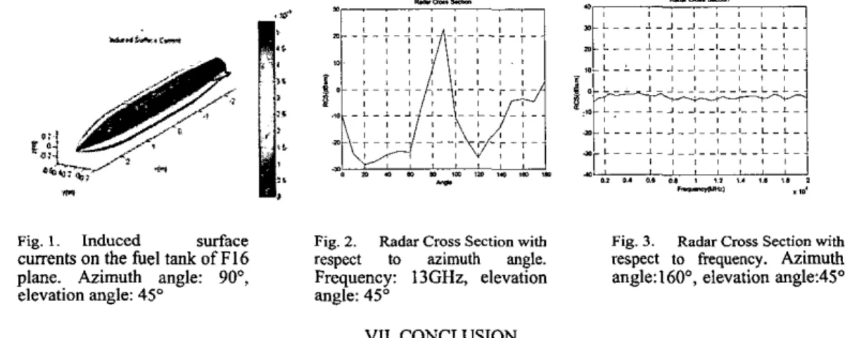
The calculations are done on the triangular mesh model of fuel tank of F16 planes. The shape of the body is
seen in Figure 1. The model consists of 136619 triangles and the calculations last for less than one minute on a Pentium IV PC. The RCS results of fuel tank are seen in Figures 2 and 3.
Fig. 1. Induced surface Fig. 2. Radar Cross Section with Fig. 3. Radar Cross Section with
currents on the fuel tank of F16 respect to azimuth angle. respect to frequency. Azimuth plane. Azimuth angle: 90°, Frequency: 13GHz. elevation angle: 160°, elevation angle:4S0 elevation angle: 45” angle: 45”
VII. CONCLUSION
The Physical Optics method is used to find the Radar Cross Section of large bodies, partitioned into triangular meshes. For each triangular plate-the PO approxsimation to the scattered field is obtained analytically. Using the above formulation, it is seen that RCS can be calculated for any object modeled by triangles of any size. The only limitation to the triangle size can be the shape of the object, that is for round objects the original shape of
the body changes if the %angles are too large. The calculations are done on the triangular mesh model of fuel
tank of F16 airplanes.
ACKNOWLEDGEMENT
We greatfully thank to Turkish Aircraft Industries Inc. (TUSAS) for their support to this work. REFERENCES
[ 11 R.F. Harrington, “Time-Harmonic Electromagnetic Fields”, McGraw-Hill, New York, 1962.
[2] C.A. Balanis, “Advanced Engineering Electromagnetics”, Wiley, New York, 1989.
[3] J.H. Richmond, “The Basic Th,eory of Harmonic Fields, Antennas and Scattering”, Ch. 4, The Radiation Integrals. Ohio State University Electro Science Laboratory, 1985.