PROPOSAL FOR A SOFTWARE MODEL
BASED ON THE CRITICAL ANALYSIS OF PACKAGES
USED IN INTERIOR ARCHITECTURE
A THESIS
SUBMITTED TO THE DEPARTMENT OF
INTERIOR ARCHITECTURE AND ENVIRONMENTAL DESIGN
AND THE INSTITUTE OF ECONOMICS AND SOCIAL SCIENCES
OF BİLKENT UNIVERSITY
IN PARTIAL FULFILLMENT OF THE REQUIREMENTS
FOR THE DEGREE OF
MASTER OF FINE ARTS
By
Burcu Gökçen Bozdağ January, 2008
I certify that I have read this thesis and that in my opinion it is fully adequate, in scope and in quality, as a thesis for the degree of Master of Fine Arts.
Assist. Prof. Dr. Burcu Şenyapılı (Principal Advisor)
I certify that I have read this thesis and that in my opinion it is fully adequate, in scope and in quality, as a thesis for the degree of Master of Fine Arts.
Prof. Dr. Bülent Özgüç
I certify that I have read this thesis and that in my opinion it is fully adequate, in scope and in quality, as a thesis for the degree of Master of Fine Arts.
Assist. Prof. Dr. H. Murat Karamüftüoğlu
Approved by the Institute of Fine Arts
ABSTRACT
PROPOSAL FOR A SOFTWARE MODEL
BASED ON THE CRITICAL ANALYSIS OF PACKAGES
USED IN INTERIOR ARCHITECTURE
Burcu Gökçen Bozdağ
MFA in Interior Architecture and Environmental Design Supervisor: Assist. Prof. Dr. Burcu Şenyapılı
January, 2008
Interior architectural education and practice employ various different general purpose software packages. Nonetheless, this study claims that as none of packages is
developed specifically for interior architectural design process and purposes, both interior architecture education and market seek ways to fulfill their specific needs. This study aims at proposing a model for domain specific software for interior architecture. Within this conception, initially, general purpose and domain specific CAAD software used in interior architecture are defined. Then, selected software are analyzed according to ‘drawing’, ’transformation’, ‘view’, ‘rendering’ and ‘other’ features. Interior architectural domain specific requirements are obtained as a result of these analyses and comparisons. Consequently, questionnaires and interviews are performed with interior architectural students and professionals in order to determine user needs. The analysis of the user needs provide significant background
information about software features and quality attributes of the proposed model.
Keywords: Interior Architecture, CAAD, General Purpose Software, Domain Specific Software, Software Features, Software Quality Attributes
ÖZET
İÇ MİMARLIKTA KULLANILAN YAZILIM PAKETLERİNİN
KRİTİK ANALİZİ SONUCUNDA BİR MODEL ÖNERİSİ
Burcu Gökçen Bozdağ
İç Mimarlık ve Çevre Tasarımı Yüksek Lisans Programı Danışman: Yrd. Doç. Dr. Burcu Şenyapılı
Ocak, 2008
İç mimarlık eğitiminde ve piyasasında çok fazla sayıda genel amaçlı bilgisayar yazılımı kullanılmaktadır. Ancak, bu çalışmada da belirtildiği gibi bu genel amaçlı yazılımların hiçbiri iç mimarlık tasarım süreci ve amacı çerçevesinde
geliştirilmediğinden, eğitim ve piyasada iç mimarlığa özel ihtiyaçların giderilmesi için yeni yollar aranmaktadır.
Bu çalışmada iç mimarlık için özel amaçlı bir bilgisayar yazılımı modeli
geliştirilmesi amaçlanmıştır. Bu bağlamda, öncelikle iç mimarlıkta kullanılan genel ve özel amaçlı bilgisayar destekli mimari tasarım yazılımları belirlenmiştir. Daha sonra, seçilen bilgisayar yazılımlarının ‘çizim’, ‘dönüşüm’, ‘görünüş’, ‘kaplama’ ve ‘diğer’ özellikleri doğrultusunda analizleri yapılmıştır. Yapılan analizler ve
karşılaştırmalar doğrultusunda iç mimarlık alanına özel gereksinimler tespit
edilmiştir. İzleyen bölümde ise kullanıcı gereksinimlerini belirlemek için iç mimarlık öğrencileri ve bu alanda çalışan uzmanlar ile anket ve görüşmeler yapılmıştır. Bu anket ve görüşmeler neticesinde oluşturulan analizler önerilen modelin yazılım özellikleri ve kalite özellikleri hakkında önemli bilgiler sunmaktadır.
ACKNOWLEDGEMENTS
Foremost, I would like to thank my supervisor Assist. Prof. Burcu Şenyapılı for the help, encouragement, guidance and support she provides during my thesis study. It’s a pleasure and a great chance for me to meet and work with her. Without her
guidance, this thesis will not be possible. I owe most of this study to her.
Furthermore, I am always indebted to my family, especially to my mother Mukaddes Çağatay, my father Ünal Çağatay and my brother Oytun Çağatay, who are beside me whenever I need with their invaluable love, support, motivation and patience during my thesis study and in my entire life.
Last but not least, I would also grateful to my husband Selçuk Bozdağ for his invaluable love, technical advise, support and understanding throughout my thesis study.
TABLE OF CONTENTS
SIGNATURE PAGE ... ii ABSTRACT ... iii ÖZET ... iv ACKNOWLEDGEMENTS ... v TABLE OF CONTENTS ... vi LIST OF TABLES ... ixLIST OF FIGURES ... xii
1. INTRODUCTION... 1
1.1 Problem Statement ... 3
1.2 Aim and Scope ... 3
1.3 Context and Structure of the Thesis ... 4
2. COMPUTER AIDED ARCHITECTURAL DESIGN... 7
2.1 Development of CAAD ... 7
2.2 Use of CAAD Software in Architecture ... 10
2.3 Classification of CAAD Software ... 11
2.3.1 General Purpose Software ... 15
2.4 CAAD Software used in Interior Architecture ... 17
2.4.1 Commonly used General Purpose Software ... 17
2.4.1.1 AutoCAD ... 18
2.4.1.2 3D Studio Max ... 19
2.4.1.3 ArchiCAD ... 20
2.4.2 Commonly used Domain Specific Software ... 21
2.4.2.1 Giotto ... 21
2.4.2.2 Arcon ... 25
2.4.2.3 WebDekor ... 26
3. CRITICAL ANALYSIS OF CAAD SOFTWARE USED IN INTERIOR ARCHITECTURE ... 28
3.1 Comparative Analysis of Software Packages ... 28
3.1.1 Analysis of CAAD Objects and Operations ... 28
3.1.1.1 CAAD Objects ... 29
3.1.1.2 CAAD Operations ... 31
3.1.2 Analysis of Features of CAAD Software ... 33
3.1.2.1 General Purpose CAAD Software ... 34
3.1.2.2 Domain Specific CAAD Software ... 39
3.1.2.3 Comparison of Features in General Purpose and Domain Specific CAAD Software ... 45
3.2 Analysis of User Preferences ... 47
3.2.1 Analysis of Students’ Preferences ... 47
3.2.1.1 Assumptions ... 47
3.2.1.2 Questionnaire ... 48
3.2.1.3 Sample Groups ... 48
3.2.1.4 Findings ... 50
3.2.2 Analysis of Professionals’ Preferences ... 74
3.2.2.1 Assumptions ... 74
3.2.2.2 Interview ... 75
3.2.2.3 Sample Groups ... 75
4. PROPOSED MODEL ... 100
4.1 Features of the Proposed Model ... 102
4.2 Quality Attributes of the Proposed Model ... 108
4.3 Discussions ... 112 5. CONCLUSION ... 117 BIBLIOGRAPHY ... 120 APPENDICES ... 124 APPENDIX A ... 125 A.1 Questionnaire ... 126 A.2 Interview ... 129 APPENDIX B ... 132
B.1 CAAD Software used in Interior Architecture ... 133
B.2 Some Examples of Interior Architectural Drawings ... 134
LIST OF TERMS ... 138
LIST OF TABLES
Table 3.1 Comparison of ‘drawing’ features in general purpose CAAD software .... 35 Table 3.2 Comparison of ‘transformation’ features in general purpose CAAD
software ... 36 Table 3.3 Comparison of ‘view’ features in general purpose CAAD software ... 37 Table 3.4 Comparison of ‘rendering’ features in general purpose CAAD software . 38 Table 3.5 Comparison of ‘other’ features in general purpose CAAD software ... 39 Table 3.6 Comparison of ‘drawing’ features in domain specific CAAD software .... 41 Table 3.7 Comparison of ‘transformation’ features in domain specific CAAD
software ... 42 Table 3.8 Comparison of ‘view’ features in domain specific CAAD software ... 43 Table 3.9 Comparison of ‘rendering’ features in domain specific CAAD software . 44 Table 3.10 Comparison of ‘other’ features in domain specific CAAD software ... 45 Table 3.11 Comparison of features in general purpose and domain specific software
... 46 Table 3.12 Reasons for utilizing a specific CAAD software package in conceptual
design phase ... 56 Table 3.13 Reasons for discontent for a specific CAAD software package in
conceptual design phase ... 57 Table 3.14 Reasons for utilizing a specific CAAD software package in project
development phase ... 59 Table 3.15 Reasons of discontent for a specific software package in project
Table 3.16 Reasons for utilizing a specific CAAD software package in presentation
phase ... 62
Table 3.17 Reasons for discontent for a specific CAAD software package in presentation phase ... 63
Table 3.18 Students’ needs in terms of software features ... 70
Table 3.19 Students’ needs in terms of software quality attributes ... 71
Table 3.20 Reasons for utilizing a specific CAAD software package in conceptual design phase ... 81
Table 3.21 Reasons for discontent for a specific CAAD software package in conceptual design phase ... 82
Table 3.22 Reasons for utilizing a specific CAAD software package in project development phase ... 84
Table 3.23 Reasons for discontent for a specific software package in project development phase ... 85
Table 3.24 Reasons for utilizing a specific CAAD software package in presentation phase ... 87
Table 3.25 Reasons for discontent of a specific CAAD software package in presentation phase ... 88
Table 3.26 Professionals’ needs in software features ... 95
Table 3.27 Professionals’ needs in terms software quality attributes ... 96
Table 4.1 ‘Drawing’ features of the proposed model ... 104
Table 4.2 ‘Transformation’ features of the proposed model ... 105
Table 4.5 ‘Other’ features of the proposed model ... 108
Table 4.6 ‘Ease of use’ attribute of the proposed model... 110
Table 4.7 ‘Reliability’ attribute of the proposed model ... 110
Table 4.8 ‘Efficiency’ attribute of the proposed model ... 111
Table 4.9 ‘Flexibility’ attribute of the proposed model ... 111
LIST OF FIGURES
Figure 3.1 2D CAAD objects ... 29
Figure 3.2 3D CAAD objects ... 30
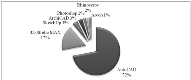
Figure 3.3 Percentage distribution of gender of students ... 49
Figure 3.4 Percentage distribution of the use of computers by students ... 49
Figure 3.5 Distribution of the use of computers by students ... 50
Figure 3.6 Percentage distribution of the use of software packages students utilize . 52 Figure 3.7 Distribution of the use of the given software packages in the questionnaire ... 52
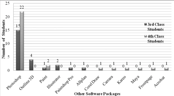
Figure 3.8 Distribution of the use of other written software packages ... 53
Figure 3.9 Percentage distribution of the use of software packages in conceptual design phase ... 55
Figure 3.10 Distribution of the use of software packages in conceptual design phase according to 3rd and 4th year students ... 55
Figure 3.11 Percentage distribution of the use software packages in project development phase ... 58
Figure 3.12 Distribution of the use of software packages in project development phase according to 3rd year and 4th year students ... 58
Figure 3.13 Percentage distribution of the use of software packages in presentation phase ... 61
Figure 3.14 Distribution of the use of software packages in presentation phase according to 3rd and 4th year students ... 61
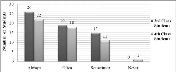
Figure 3.16 Distribution of satisfaction with general purpose CAAD software ... 64 Figure 3.17 Percentage distribution of needing domain specific CAAD software in
interior architectural design ... 65 Figure 3.18 Distribution of needing domain specific CAAD software in interior
architectural design ... 65 Figure 3.19 Percentage distribution of students’ tendency in using a new domain
specific interior architectural software ... 66 Figure 3.20 Distribution of students’ tendency in using a new domain specific
interior architectural software ... 66 Figure 3.21 Percentage distribution of preferences for using a specific CAAD
software ... 67 Figure 3.22 Distribution of preferences for using a specific CAAD software
according to 3rd and 4th year students ... 68 Figure 3.23 Percentage distribution of students’ needs in software features and
software quality attributes ... 72 Figure 3.24 Distribution of students’ needs in software features and software quality
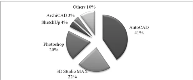
attributes ... 73 Figure 3.25 Percentage distribution of qualifications of professionals ... 76 Figure 3.26 Percentage distribution of the use of software packages professionals
utilize ... 78 Figure 3.27 Distribution of the use of the given software packages in the interview 78 Figure 3.28 Distribution of the use of other software packages ... 79 Figure 3.29 Percentage distribution of the use of software packages in conceptual
design phase ... 80 Figure 3.30 Distribution of the use of software packages in conceptual design phase
Figure 3.31 Percentage distribution of the use of software packages in project
development phase ... 82 Figure 3.32 Distribution of the use of software packages in project development
phase according to professionals... 83 Figure 3.33 Percentage distribution of the use of software packages in presentation
phase ... 86 Figure 3.34 Distribution of the use of software packages in the presentation phase
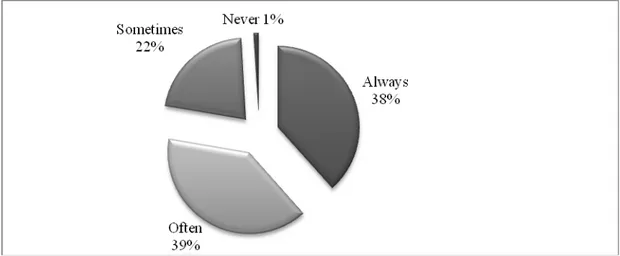
according to professionals ... 86 Figure 3.35 Percentage distribution of satisfaction with general purpose CAAD
software ... 89 Figure 3.36 Distribution of satisfaction with general purpose CAAD software ... 89 Figure 3.37 Percentage distribution of criteria related to dissatisfaction of general
purpose CAAD software ... 90 Figure 3.38 Percentage distribution of needing domain specific CAAD software in
interior architectural design ... 91 Figure 3.39 Distribution of needing domain specific CAAD software in interior
architectural design ... 91 Figure 3.40 Percentage distribution of criteria related to the domain specific CAAD
software need in interior architectural design ... 92 Figure 3.41 Percentage distribution of professionals’ tendency in using a new domain specific interior architectural software ... 92 Figure 3.42 Distribution of professionals’ tendency in using a new domain specific
interior architectural software ... 93 Figure 3.43 Percentage distribution of preferences for using a specific CAAD
Figure 3.45 Percentage distribution of professionals’ needs in software features and
software quality attributes ... 97
Figure 3.46 Distribution of professionals’ needs in software features and software quality attributes ... 97
Figure 4.1 Software model procedures ... 100
Figure 4.2 Components of the proposed model ... 101
Figure 4.3 Components of the software features and quality attributes ... 101
Figure 4.4 Features of the proposed model ... 102
1. INTRODUCTION
The need of an interior space first emerged in prehistoric times to meet primary human needs of getting warm, sleeping and eating. Despite this fact, the profession of interior architecture has not been recognized for centuries. Until the twentieth century, architects, engineers, builders, joiners, plasterers, textile designers, fine artists and furniture designers had advised on the arrangement of the interiors rather than interior architects (Massey, 2001).
Interior architecture first appeared as the continuum of interior decoration. With the improving needs of society, interior decoration became a profession called interior design. Interior design can be defined as “a multi-faceted profession in which creative and technical solutions are applied within a structure to achieve a built interior environment” (NCIDQ, 2004). However, there is still a distinction between interior architecture and interior design. Interior architecture has strong links with architecture. Interior architecture is composed of design choices embedded within the building inside as well as out, and as such must be housed within the practice of architecture and professional architectural services (Hildebrant, 2004). Although the design processes of interior architecture and interior design share the same
procedural sequence and a core discipline vocabulary; interior design, both as a discipline and in its product, is free of the weight of the interior architecture
Through the history, interior spaces were considered as an inseparable part of the entire structure and most of the time they were designed by architects. Also,
architectural movements and styles of the time affected interior designers and design applications. In the twentieth century, influenced by architecture, interior
architectural professionals presented two different approaches (Tate & Smith, 1986); those closely followed historical traditions of the past and those who explored innovation and invention. The second approach was carried by the works of Frank Lloyd Wright (1867-1959) who was considered to be the pioneer of modern interiors since he was the first to develop “interpenetration of interior and exterior space” (Tate & Smith, 1986, p. 265). Wright’s unifying approach of interior and exterior is significant in interior architecture’s emerging as a new specialized branch within architecture (Demirbaş, 2001).
The emergence of interior architecture as an independent discipline may seem recent when compared to the history of architecture, yet it had a strong impact. The
communication and interaction between the two disciplines are dense and close. Interior architecture borrows a lot from architecture, such as its terminologies, theories and styles. Interior architecture also makes use of architectural software. In education and practice, interior architecture generally uses software comprising operations related to a large spectrum of architectural design activities.
1.1 Problem Statement
As interior architecture revealed as a new discipline depending on architecture, they are seen inseparable in many ways. Interior architects have been using the same tools with architects in design and practice, and recently with the emergence of
technological tools they began using the same software packages. However, interior architecture is a distinct design field which differs in focusing on interior space’s detailed design requirements related to color, texture, lighting, heating, acoustics (TMMOB, 2005) and owes its existence to these details. These details put forth a special characteristic for interior architecture and express its “otherness”
(Havenhand, 2004, p. 38). This thesis questions whether interior architecture needs domain specific computer aided architectural design (CAAD) software developed solely and specifically for interior architectural requirements. In this framework, it is worth examining whether CAAD software suffices the requirements of interior architecture fully. If not, it shall be examined what may be proposed when constructing a framework for software specific to interior architectural domain.
1.2 Aim and Scope
CAAD software today are mostly developed for general purpose use and then are refined in order to fit one or other professions (Kurman, 1998). The software
packages used in interior architecture are developed similarly for general purpose or architectural purpose, not specifically for interior architectural design purposes.
individual packages. Yet, an agreement on specific interior architectural domain software has not been established. As a result, every company whether develops a new software package from scratch and/or customizes a general purpose CAAD software by integrating plug-ins to them (Eastman, 1999). Thus, there are plenty of software packages that are seemingly causing a chaos in interior architectural practice.
Although various domain specific software packages are utilized in practice, none seems to be extensively utilized in education. The students are still using general purpose or architectural software while developing their projects. Furthermore, students who are learning to use general purpose software often have difficulties when they begin working in such companies.
This thesis presents an analysis of CAAD software used in interior architectural education and practice, studying the adequate and inadequate aspects of the
commonly used CAAD software. Based on these analyses, it is aimed to propose a model for establishing domain specific software for interior architectural design purposes.
1.3 Context and Structure of the Thesis
This thesis comprises a critical analysis of commonly used software in interior architecture and establishes a model that combines the adequate aspects of general purpose and domain specific software, along with user needs gathered from
This study consists of five chapters and further chapters of the thesis are organized as follows:
In the second chapter, entitled “Computer Aided Architectural Design”, overall information about CAAD is given. First, the development of CAAD parallel to the development of computers is represented. Here, CAAD software are classified as general purpose and domain specific. Then, the use of computers in interior architectural design and how it affected the way architects and interior architects work are explained. Lastly, the CAAD software used in interior architecture are discussed within the previously introduced classifications.
The third chapter which is entitled as “Critical Analysis of CAAD Software Used in Interior Architecture” contains the analysis part of the thesis and comprises of two main parts. In the first part, comparative analysis of software packages are specified including detailed analysis of CAAD objects and operations used in CAAD software, and analysis of features of general purpose and domain specific software. General purpose CAAD software that are selected and analyzed are AutoCAD1, 3D Studio2 MAX and ArchiCAD3 in terms of their being produced by the leading companies in 2D drawing, 3D modeling and building information modeling (BIM), and also being the most commonly utilized packages in the world and especially in Turkey.
Moreover, domain specific CAAD software, such as Giotto, Arcon4 and WebDekor5
are chosen for their different purposes of use in interior architecture; such as kitchen, bathroom and ceramics design. In the second part, analyses of the user preferences are examined. These analyses include questionnaires with the students and interviews with the professionals. The assumptions over students and professionals, sample groups and contents, and the findings of the questionnaires and interviews are also given.
The fourth chapter of the thesis, entitled “Proposed Model”, covers the features and quality attributes of the proposed model. In this chapter, based on the previous analyses and findings, an extensive model is developed and introduced. The
presentation of the model is followed by discussions, where a self-assessment about the proposed model is made.
The final and conclusive chapter of the thesis highlights the important points of the analysis, the gathered data and the proposed model. The contribution of this study to literature and suggestions for further work are mentioned here. This chapter is followed by a list of references and appendices. The appendices include the
questionnaire and interviews, and present the information about the general purpose and domain specific software packages used in interior architectural education and practice.
2. COMPUTER AIDED ARCHITECTURAL DESIGN
Computer aided architectural design (CAAD), as a term, is a bridge between computers and architecture while emphasizing the use of computer aid in architecture. Computers are used as tools and as media in various disciplines. Architecture is one of these disciplines within which the effects of computers are seen widely. Although the use of computers in architecture is new, compared to many other tools, the impacts and the consequences have varied the way architectural design progresses (Coyne, 1992).
2.1 Development of CAAD
The development of the computers dates back to 1940s. First computers were slow, large and expensive to buy, and were designed especially for commercial use only. There were lots of efforts to make them affordable and widespread. For instance, in 1959, with the invention of the transistor and chip, computers became smaller, faster and reliable (Woodward & Howes, 1997). These innovations fastened developments and in 1970s, the personal computers (PC) were developed. PCs were soon used in different professions, in various offices or even homes because of its smaller size, usefulness in accomplishing everyday tasks and affordability (Kalay, 2004).
graphics of the old computer systems with good quality graphics, the costs of the PCs dropped while affecting the affordability of PCs to explode (Eastman, 1999). The development of the computers has never stopped and computers today are in almost every tool we used.
In the past, architects were limited to the straight lines and arcs of circles with the traditional tools like parallel bars, triangles, compasses, scales and protractors (Mitchell, 1999). The developments in the information technology also influenced the way architects, interior architects and designers worked. Instead of using the traditional tools, computers were utilized in architectural offices due to their efficiency. Computers were first used as a drafting tool primarily to increase the efficiency of conventional modes of production (Silver, 2006).
However, it took a long time for architects to employ computers as a design medium during their design process. According to Straub (1986) there were three issues affecting the use of computers in architectural design. The first two issues, ‘cost’ and ‘time’, he claims, slowed down the use of computers. At first, computer technology was new and expensive to buy, therefore only few architectural offices afforded to buy and use it properly. Moreover, architects had to gain architectural computer skills which were difficult and time consuming. The third issue was ‘quality’, which increased computer use in architecture. Architects started to use computers to improve the quality of the drawings. However, the use of computers in architecture, replaced hand drawings by 3D models and computer visualizations while allowing new architectural forms to emerge (Mitchell, 1999).
In spite of the situation in the architectural practice, computers were of more interest in the academic field. There were various attempts to improve the computer aid in architecture. The leading attempt was Sketchpad which can be considered as the first architectural software. Sketchpad was developed by Ivan Sutherland in MIT in 1963 (Sutherland, 1963) and it is considered to be one of the important milestones in the emergence of CAAD and CAAD software. Sketchpad system made the
communication between ‘man’ and ‘machine’ easier by strengthening and correcting the lines, intended to draw, with several functions and constraints. Most of the currently used CAAD systems have developed in similar ways to Sketchpad.
Computers and CAAD software have lead to different discussions in both academia and practice. One of the most important discussions is whether computers are solely used as design tool for drafting and modeling purposes instead of traditional tools, or they are used as design media assisting the design activity (Gero, 1986). Some researchers as Coyne (1992) stated that computers had minor effect on design activity but they were commonly used as a design tool for drawing documentation and 3D visualization. This might be valid for the first years of computer use in architecture but today the situation is different. Currently, researchers claim that computers are not only tools but also design media to help designers during project design. As Mitchell (1999) mentioned, computers produced a revolution in design, by allowing architects to imagine, develop, and explore innovative concepts that have proved to be impossible in the past.
group supports the use of CAAD software and its benefits, while the other group thinks the CAAD software is not useful during project design. Woodward and Howes (1997) support the use of CAAD software in architecture and mention benefits of CAAD software which include the following issues;
Drawings can be prepared more quickly with the computers and the
information loaded on a single computer drawing contains more information than a hand drawn one could. Furthermore, computers provide a more systematic way of working, the paper print of a drawing produced with a computer may look more elegant and detailed than any drawing produced by hand could be. Lastly, the files of drawings can more easily and more quickly be sent to consultants or contractor than its paper counterpart could be (p.91).
Another group of researchers think that CAAD software is unbeneficial in
architectural design as Turk (2001). Turk stated four reasons for unbeneficial use of CAAD software in some design projects:
First, in terms of representation, the predetermined computer objects limits designers’ creativeness. Second, in terms of situatedness, designers’ being in an “artificial world” affects the designers’ perception in a negative way. Third, in terms of communication, computers restrict the information flow between the actors in the design process. And last, in terms of particularism and holism, it is hard to get design parts as a whole on the computer.
Even though computers and CAAD software have lead to different discussions, computer use has increased within the past few years and different CAAD software were developed for various purposes of use in architecture.
2.2 Use of CAAD Software in Architecture
In architecture and interior architecture, CAAD software are used for several purposes, such as; documentation, specification writing, drafting, two dimensional drawing (2D), three dimensional (3D) modeling, animation, etc. (Coyne, 1992). Until
1970s computers were not widespread and were barely used for calculation and documentation. In 1970s, architects and designers used the available computers and CAAD software for only specification writing and drafting purposes due to
computer’s accuracy and speed. In 1980s, several companies like Autodesk, VersaCad, Summagraphics, Microstation, and others released software that
supported drafting aspects of architectural design (Kalay, 2004) while augmenting the computer use in architecture.
Also, the developments in the computer technology affected the use of CAAD software in architecture. Once employed as pure 2D drafting systems, when
architects met with simple 3D shapes and forms, and elementary rendering features, they began using CAAD software not only for drafting, but also for modeling purposes. Additionally, at the end of 1980s, several modeling features such as ‘smooth shading’, ‘shadow casting’ and ‘solids modeling’ features, distinguished CAAD software from only being drafting systems (Richens, 1992). Furthermore, 1990s brought the general affordability of 3D modeling, rendering, animation and multimedia presentations (Schmitt, 1999). Nowadays, computers are almost indispensible parts of design and presentation phases of architecture.
2.3 Classification of CAAD Software
Despite the context of this study covers a categorization of CAAD software as ‘general purpose’ and ‘domain specific’, it is worthwhile to classify CAAD software
‘building information modeling’ (BIM) to understand the development of 3D modeling methods and the terms that are mentioned in this study.
In the 1970s, the development of CAD software took two different routes: ‘geometric modeling route’ which supports mainly the needs of mechanical engineering
applications in the automotive and aerospace industries; and ‘building-specific route’ which supports the needs of the construction industry (Kalay, 2004).
To start with, ‘geometric modeling’ is the simplest form of modeling approach which includes wire frame modeling, surface modeling and solid modeling. Firstly, wire frame modeling is the oldest computational representation of geometric forms in which the shapes are represented by a collection of the edges and vertices of the shapes represented, leaving to the viewer the task of inferring the volume and other properties of the shape from these outlines (Mantyla, 1982; Kalay, 2004). Wireframe models are easy to use but weak in the representation of objects in terms of well-formedness, generality and completeness (Kalay, 2004). Secondly, surface modeling is based on wireframe models that could later be patched by the surfaces. The objects created with surface modeling method includes only the surface representations of the 3D object and if cut, it exhibits its empty interior and interiors of the faces which it is composed of (Woodward & Howes, 1997). Surface modelers are especially developed in order to expand the surface properties such as its smoothness. However, since most of the surface modeling software did not assist most CAAD operations, another modeling method is developed. In the late 1970s, solid modeling method is developed to build complex volume enclosing sets of surfaces with ‘boolean operations’ (union, intersection and subtract) from simpler solid objects (Whitted,
1982; Sacks, Eastman, & Lee, 2004). Solid modeling is the most enhanced geometric modeling method which provides accurate representation of a 3D shape, by
derivation of any shape measurements, by cutting of sections and by automatic dimensioning features (Sacks, Eastman, & Lee, 2004). Even now, most of the CAAD systems developed for Architecture, Engineering and Construction (AEC) industry make use of solid modeling method (Eastman, 1999), like one of the major CAAD software package, AutoCAD.
Although ‘geometric modeling’ opens up new alternatives and ways of working in architectural design, there are also several problems in using this method. The main problem is the spatial coordinate system which every geometrically defined object based on (Saitz, 2005). For instance, if there appears a change in the design, the user has to revise major sections of the drawing or draw the entire drawing from scratch. This process of revising a solid model is a tedious process and also, defining a 3D solid shape requires more effort than defining its equivalent 2D representations (Sacks, Eastman, & Lee, 2004). These given drawbacks about ‘geometric modeling’ lead to a new modeling method, ‘parametric modeling’ to emerge.
‘Parametric modeling’ is simply rooted in ‘geometric modeling’ with extending its ease of use and usually utilized in mechanical engineering and building design. “A parametric model is defined by the rules and constraints, which define different aspects of the building and their relationship to each other” (Katz, 2007). Therefore, the geometry identified in the ‘parametric modeling’ has strong links with its
in ‘parametric modeling’ is non uniform rational B-Spline (NURBS) which is used to generate curves and surfaces (Monedero, 2000). This feature is beneficial for the users to model an object more efficiently and in a considerably lower time.
Being a successful modeling method, ‘parametric modeling’ also possesses some difficulties. The employment of ‘parametric modeling’ software has not been widespread until recently, due to its being perceived as highly sophisticated and expensive software (Hernandez, 2006). The highly sophisticated nature of the ‘parametric modeling’ really creates a big difficulty to users and decreases its efficiency during the modeling process. As the drawing becomes more complex, the number of the parameters and the geometric constraints that should be defined becomes extensive (Lee, Sacks, & Eastman, 2006) and difficult to cope with.
Catia6 and 3D Studio Max can be given as the sufficient examples of ‘parametric modeling’ method. Although AutoCAD is a geometric modeling tool, with the available parametric engines developed specially for AutoCAD, it can be used parametrically.
As the computer technology developed to support extensive parametric inputs, BIM emerged based on ‘parametric modeling’. BIM supports building components, their behavior and relation to each other. This is a new modeling method, used in AEC industry from conceptual design to construction phase while improving the collaboration between architects and engineers.
In addition, BIM is an extensive modeling method which involves different aspects in a building that needs to be modeled; first the building components, such as walls, doors, etc. and then, abstract geometrical concepts to use in early design phases (Eastman, 1999). BIM provides various advantages in terms of ‘productivity’, “the ability to rapidly generate design alternatives at different levels and elimination of errors that result from the disparity between different drawings in current practice” (Sacks, Eastman, & Lee, 2004, p. 291). Revit7 produced by Autodesk and ArchiCAD by Graphisoft are considered to be the forerunner software packages in BIM.
The emergence of 3D modeling methods has offered new ways of working and presentation skills to designers. The foundations are laid with geometric modeling and are developed into the BIM method which is supporting the design process and collaboration between professionals. BIM will surely continue to develop while proposing innovative ideas for architectural design.
Within this framework, the existing CAAD software may be further grouped according to their purpose of utilization as ‘general purpose’ and ‘domain specific’ software.
2.3.1 General Purpose Software
General purpose software comprise software packages that are developed to be useful in a wide range of tasks or requirements. They can be adapted to different
fields, such as; architecture, engineering, etc. As Richens (1992) defines, the general purpose software understand lines and circles, text, raster images and also, in some cases, 3D forms such as; planes, surfaces or solids. However, they have low
intelligence about buildings or architecture, but they are highly flexible software which means the same software can be adapted to a building, a landscape or a ship (Richens, 1992). A typical example of general purpose CAAD software is AutoCAD, which is helpful in building design, architecture, landscape architecture and
mechanical, civil, electrical engineering fields.
2.3.2 Domain Specific Software
Domain specific software comprise software packages that are developed to be useful for a specific kind of task or requirement. They are simply developed by the specialization of general purpose software to meet the needs of a specialized field in the market.
Until 1980s various software are developed as CAAD packages, most of them being general purpose software. Then, some companies started to develop special features and software for particular fields. (Eastman, 1999). This process led to software specialization, resulting in the domain specific software to emerge.
One of the best examples of the leading companies that develop domain specific software is Graphisoft, with its architectural domain specific software package ArchiCAD. The architectural elements ArchiCAD deals with are slabs and walls, doors and windows, roofs and roof lights which make it more flexible compared to
is presumed that a domain specific software package implies only the interior architectural domain specific software.
2.4 CAAD Software used in Interior Architecture
There are plenty of different software packages used in interior architecture from 2D drawing to 3D modeling that support different phases of design process. Even the software used in the interior architectural education and practice differ. While the students employ the general purpose CAAD software for 2D drawing and 3D modeling purposes, it is prominent that professionals utilize the domain specific software that are developed for each company most of the time.
The following parts of the study covers the most commonly used general purpose and domain specific software packages in education and practice.
2.4.1 Commonly used General Purpose Software
In this thesis the software packages analyzed as commonly used general purpose CAAD software are AutoCAD, 3D Studio Max and ArchiCAD. These packages are chosen because they are produced by the leading companies in 2D drawing, 3D modeling and BIM, and they are also the most commonly utilized packages in the world and especially in Turkey. The detailed background information about these software packages and their features are given in the following sections.
2.4.1.1 AutoCAD
AutoCAD is a full-featured general purpose CAAD software application for 2D and 3D design and modeling by AutoDesk Inc. AutoDesk released the first version of AutoCAD in 1982 for PCs (AutoCAD, 2007a).
AutoCAD evolved from a very basic version that allows its users to draw only some primitives like lines, polylines, circles, arcs and text. It is also released as AutoCAD LT which is less featured or scaled down to spread the common use of AutoCAD for any 2D drawing facility with a fair price. Today, AutoCAD has a full set of solid modeling and 3D tools but, it still lacks some of the more advanced capabilities of solid modeling applications.
AutoCAD is varied by some vertical programs which address specific areas of interest for diverse markets, such as AutoCAD Architecture, AutoCAD Electrical and AutoCAD Civil 3D (AutoCAD, 2007a). For instance, AutoCAD Architecture allows architectural designers to draw customized 3D objects such as walls and doors. Therefore, architectural designers do not utilize primitive objects unless any particular reason arises. Similarly, AutoCAD Civil Design, AutoCAD Mechanical, AutoCAD Electrical, AutoCAD Map 3D are other examples of specific CAAD applications rooted from AutoCAD (AutoCAD, 2007a).
Furthermore, AutoCAD supports a number of application programming interfaces (API) to let developers extend its functionality (AutoCAD, 2007b). There also exists third-party AutoCAD based applications developed by other developers rather than
The well-known format DWG is the native format of AutoCAD while DXF (data exchange format) is used for data exchange. Also, AutoCAD uses DWF (drawing web format) to display its files on the internet (Jefferis, Jones, & Jefferis, 2002). AutoCAD has twenty-two stable versions ending with AutoCAD 2008. In addition, AutoCAD 2009 is in still beta version up to date.
2.4.1.2 3D Studio Max
3D Studio Max is a general purpose 3D modeling application and initially developed by Discreet. Then, in 1999 Autodesk purchased Discreet and reorganized it under AutoDesk Media and Entertainment in 2005 (Bartz, 2000).
3D Studio Max is widely used as 3D animation software to create rich and complex design visualizations with outstanding modeling features. Character studio feature lets creators to animate models. Also, 3D Studio Max has various parametric modeling capabilities through advanced modeling methods such as polygon modeling, non uniform rational B-splines (NURBS) and surface modeling (3D Studio MAX, 2007). Models can be created easily by assigning parameters to predetermined objects; boxes, cylinders, planes, spheres, spindles, prisms, etc. Furthermore, it is possible in 3D Studio Max to define streamlined event sequences. In 3D Studio Max terminology it is called as ‘dynamics’. For instance, ‘particle emission’ is a ‘dynamic’ and it has up to six different types such as spray, blizzard and snow (AutoDesk 3D Studio MAX, 2007).
plugged into the software. Nonetheless, 3D Studio Max has its own renderer called ‘scanline’ which is a superior method of rendering improved by various features such as global illumination, radiosity and ray tracing (AutoDesk 3D Studio MAX, 2007). The most current version of the software is 3D Studio Max 2008 up to date.
2.4.1.3 ArchiCAD
ArchiCAD is an architectural software application developed by Graphisoft and initially released in 1982 (ArchiCAD, 2007a). ArchiCAD introduces the concept of smart objects which was not available in other CAAD software applications in 1980s. These smart objects allows user to create buildings with walls, doors, windows and furniture in a parametric fashion meaning that any of these object can be transformed by providing parameters for their object attributes (ArchiCAD, 2007b). It is possible to work with either a 2D or 3D representation. It is fairly easy to switch between 2D and 3D perspectives. All drawing facility is established on ‘virtual building’ essence. A ‘virtual building’ comes along with virtual structural elements. ‘Virtual Building’ is defined by Wallbank (2008) as;
"Unlike a simple 3D model on a computer, the Virtual Building contains a great deal more information about the building's materials and characteristics. It is a 3D digital database that tracks all elements that make up a building. This information can include surface area and volume, thermal properties, room descriptions, price, specific product information, window, door and finish schedules, and more. ArchiCAD mostly stands for architectural software featuring building information modeling (BIM) experience"
ArchiCAD can import various CAAD software formats such as DWG and DWF to support interoperability with other applications. The newest version of ArchiCAD is ArchiCAD 11 up to date.
2.4.2 Commonly used Domain Specific Software
The commonly used domain specific software that are selected are Giotto, Arcon and WebDekor respectively. These packages are chosen because they represent different purposes of domain specific software used in interior architecture; such as kitchen, bathroom and ceramics design. Giotto is one of the oldest examples of software utilizing geometric modeling and Arcon is an example of software utilizing a parametric modeling technique. WebDekor differs in being a web based software package.
2.4.2.1 Giotto
Giotto is a domain specific software package developed by an Italian Firm in order to fulfill specific needs of Lineadecor, which is a specialized company in kitchen
furniture and accessory design with its several branches in Turkey and Europe. Giotto can be considered as an initial example of the software packages providing geometric modeling. However, Giotto did not develop along with the technical improvements and was defeated with the new improvements in CAAD technology. Thus, Lineadecor switched off to another software package by mid 2007.
On the other hand, Giotto has the capability to be adapted for different companies in the practice. It has its own CAAD engine but if a plug-in supporting the pre-defined object libraries of the company is installed into, it becomes a specialized software for that specific company. Similarly, if new objects are required to be included in its object library, a new plug-in may be installed.
Due to the limited information about Giotto, its basic properties and features are depicted in accordance with the experiences of the author.
Initially, Giotto has a limited user interface at the beginning which includes the main menu. This menu directs the user to the main functions of Giotto including ‘design’, ‘3D representation’, ‘cost estimation’, ‘printing options’ and ‘other’ functions such as; software configuration, its update and language.
The user who wants to design a kitchen first selects the ‘design’ function from the main menu to prepare the 2D drawings. Then, a new empty page opens with several features existing on the toolbar. These toolbar on the upper side of the page includes ‘file’, ‘view’, ‘wall’, ‘active wall’, ‘layers’, ‘modules’, ‘menu’, zoom’ and various other features. Also, the list ‘listino’ that is placed on the left side of the page includes the pre-defined kitchen modules. The first step in the design phase is to form the walls of the kitchen based on the exact dimensions in millimeters. Next, the other building elements like columns, beams, doors and windows have to be
prepared. However, only walls are determined as a building component, column and beam representations in Giotto simply consist of rectangular blocks which is
determined by the user defined parameters. Also, windows and doors are considered as accessories and represented under the ‘listino’ menu. To place any of these elements one has to first identify on which wall these items will be placed and then has to move the element into its correct place. Afterwards, the design process starts with placing objects, starting from kitchen modules, countertops, electrical
appliances and accessories into the proper places. If ceramic covering are needed to be placed or the dimensions (height, length, width) of the modules or objects height,
length, width are needed, the menu toolbar includes the features as ‘hatching’ and ‘dimensioning’ on the top of the page. The user is limited to make modifications only in 2D front and top view of the drawing. The 3D perspectives can be taken here but it is not allowed to make any modifications there. Moreover, there is no ‘undo’ feature in the Giotto. Thus, in the case of a change or ‘undo’ situation, users either have to start from scratch or start from another saved file of the project.
After setting up the 2D drawings, the user has to save and turn back to the main interface in order to realize the project in 3D. From here, by selecting the ‘3D representation’ again a new page opens and Giotto loads the 3D modules of the prepared drawings. Actually, in Giotto all of the objects drawn are 3D, whether it is represented as 2D top view or a perspective. However, the user only has the
capability of seeing them in 3D. The materials, textures and colors can be attached to the objects drawn in ‘3D representation’, but, the user can not modify them here. If mistakes made during 2D drawing are realized in this view, or there are changes that needs to be done, these changes has to be done again in 2D drawing. This problem limits the user and extends the design process, which is a big problem especially in the market.
Moreover, in 3D representation menu, one can render the project after assigning the textures and colors, with a real time ray tracing plug-in POV-Ray (POV-Ray, 2008). Again, due to the lack of ‘undo’ command, if the color of the object is wanted to change, the next color is placed upon the old one on the same object. This situation results in the increase of the file size and increase in the duration of the rendering
take 2D drawing printouts, one has to again go back to the main menu and select the plan or side view in an identified scale.
Similarly, to estimate the cost of the project, the user needs to turn back to the main menu and select the ‘cost estimation’ feature. Giotto automatically organizes the objects drawn and the pre-determined cost values of the objects, and gives the total cost of the project. Nevertheless, if the cost of the project appears to be higher for the customer, the project should be drawn again or revised starting from 2D drawings, which means that all of the ‘3D representation’, ‘view’ and ‘cost estimation’ features have to be done again.
Furthermore, if the project is approved by the customer, the projects are then needed to be sent to the factory in order to start with the production. However, since Giotto does not support the collaboration between branches of the company through internet, all the business is done manually.
A typical design process is tried to be illustrated while mentioning the sufficient and insufficient features of Giotto. The insufficient features can be summed up as;
• The limitation in the design process due to the modular design,
• The limitation related to the quality software with its lacking commands and features and with its insufficient translation of language
• The limitation of modification of objects in 3D • The limitation of collaboration between users
• The limitation of compatibility of the drawing in another software or in another file format
2.4.2.2 Arcon
Arcon is actually is an architectural based general purpose software which is developed by a German software company, Eleco (Arcon 3D Architect, 2006). To prevent the confusion, it is important to state that the Arcon mentioned in this thesis is the Arcon Armadi Art version, which is a domain specific software package developed based on the original Arcon 3D Architect by adding the pre-defined object library of Armadi Art. Armadi Art is a company established in 1974, specializing especially in design of bathroom furniture. Later, Arcon was adapted in early 2007.
Similar to AutoCAD, which is varied by vertical programs in different markets, Arcon is also varied by vertical programs, such as; Arcon 3D Bathroom Designer, Arcon 3D Kitchen Designer, Arcon 3D Home Designer, Arcon 3D Interior Designer, Arcon 3D Home Designer Expert and Arcon 3D Architect (Arcon, 2008).
While designing with Arcon, the design starts with the aid of gridlines and projects can be modeled from ground floor to the roof in detail. Arcon works in a very similar way to ArchiCAD and includes the smart objects as well. The smart objects can be selected from a variety of pre-determined objects such as; walls, roofs, staircases, windows, doors and other elements of construction (Arcon, 2008). Also, with the calculation of light, shade, transparency and mirroring, as well as consideration of the position of the sun and the moon, a photorealistic presentation can be obtained (Arcon 3D Architect, 2006). The ‘cost estimation’ feature, which may be assigned to each object, makes the design and presentation of the project easier.
There are available plug-ins, object and texture libraries on the Arcon’s web page for the users who want to extend their use (Arcon, 2008).
2.4.2.3 WebDekor
WebDekor, as its name indicates, is a web based domain specific software developed by Virtual Décor (3D Web, 2008) for Çakmak Yapı, which is the distributor of Aparichi ceramics in Turkey. WebDekor can be used for different purposes in
interior design; especially in office, bathroom and kitchen design with different types of furniture and also with wall and floor coverings.
WebDekor is a free and an user friendly software package (3D Web, 2008) that can be learnt in a short time with the help of the directions while drawing. The pre-determined object library is not extensive like the other domain software packages. However, it includes the entire texture library derived from Aparichi ceramics.
While designing with WebDekor, initially the floor plan is defined with its walls. Then, the objects are placed with the built-in object library. All the objects drawn are in 3D and they are smart objects that can easily be modified by the user. Also, WebDekor provides navigation in 3D with user-defined views. After the objects are placed, the user can arrange which wall or floor tile to use with relevant design, positioning and number. Being an interactive software package provides various advantages for WebDekor, such as providing information about; the state of the ceramic stocks in Turkey, the number of ceramics to be ordered and the price of these orders. Moreover, it maintains collaboration between the different branches
within a company. WebDekor is a significant example among the domain specific software analyzed and gives clues about how the software will be like in the future.
3. CRITICAL ANALYSIS OF CAAD SOFTWARE USED IN
INTERIOR ARCHITECTURE
In this chapter, firstly CAAD objects and operations are defined, and features of the previously introduced general purpose and domain specific CAAD software used in interior architecture are examined according to these classifications. Then, in the analysis of user preferences part, the analyses gathered as a result of questionnaires and interviews are discussed.
3.1 Comparative Analysis of Software Packages
The comparative analysis of software packages covers the analysis of CAAD objects and operations, and analysis of general purpose and domain specific software in detail.
3.1.1 Analysis of CAAD Objects and Operations
The analysis of CAAD objects and operations are best identified by Szalapaj (2001) in his book “CAD Principles for Architectural Design”. The following issues cover the issues of CAAD objects and operations in detail.
3.1.1.1 CAAD Objects
As stated by Szalapaj (2001), CAAD objects are categorized under two main headings, 2D objects and 3D objects. 2D objects include ‘lines’, ‘grids’, ‘2D symbols’ and ‘dimensions’ (Figure 3.1). Firstly, ‘a line is a one-dimensional entity whose extend is designated by length that may exist in a one, two or three
dimensional space’ (Eastman, 1999, p. 179). ‘Lines’ create a basis for basic geometries and shapes, such as polylines, rectangles, polygons, circles, arcs and curves. Secondly, ‘grids’ are used to define guidelines on the drawing surface and they are especially required when forming the building construction system. Thirdly, the ‘2D symbols’ are the representations of a complex object that are used repeatedly in a drawing whether they are created by the users or imported from the object libraries. For instance, architectural ‘2D symbols’ include door, window, sink, toilet, etc. symbols. The last item in the 2D objects is ‘dimensions’ with which the accurate measurement of the lines, the angles and the distances are calculated.
3D objects include ‘planes’, ‘volumes’, ‘quadric surfaces’ and ‘3D symbols’ as Szalapaj (2001) mentioned (Figure 3.2). To begin with, ‘planes’ are defined with three non-collinear points that are flat and are constructed simply by creating a 2D form and extruding this form. Next, ‘volumes’ are drawn by providing parameters like length, width, height, radius to predetermined 3D volumes existing in most of the CAAD software. Some of the examples of ‘volumes’ include; blocks, spheres, hemispheres, cones and cylinders. ‘Quadric surfaces’ are generated from conic sections which are the 2D shapes formed when a plane cuts a cone at various angles. Later on, these sections are rotated 180 degree through an axis while generating a surface. Spheres, ellipsoids, hyperboloids and paraboloids are some of examples of these 3D objects (Szalapaj, 2001). Finally, ‘3D symbols’ are similar to 2D symbols and mostly created by users. While these symbols reduce the memory size of the models, each symbol can also carry additional information about their cost, size, etc (Szalapaj, 2001).
The objects that are defined by (Szalapaj, 2001) are noteworthy ones in constituting a framework for the analysis of CAAD software and the proposed model in this study.
3.1.1.2 CAAD Operations
CAAD operations are categorized into four main groups as ‘geometric
transformations’, ‘topological transformations’, ‘boolean operations’ and ‘logical operations’ (Szalapaj, 2001).
‘Geometric transformations’ modify the properties of the objects, such as shape, coordinates or angle, apart from its topology. ‘Move’, ‘rotate’, ‘scale’, ‘reflect’ and ‘shear’ transformations are some of the examples. As Szalapaj (2001) remarks
‘move’ transformation relocates a selected object to a specific distance. Next, ‘rotate’ transformation changes the objects’ angle into the specified angle. Similarly, ‘scale’ transformation modifies objects’ size into a higher or lower scale. Then, ‘reflect’ transformation (or well known as mirror transformation) mirrors an object through an axis while protecting the original shape and size. On the other hand, ‘shear’
transformation produces a distortion on the selected object while maintaining its topology.
The second CAAD operation ‘topological transformations’ allows for changing the object’s topology and its spatial features that are connected to each other. The ‘topological transformations’ are also effective in providing more complex shapes out of simple geometric forms (Eastman, 1999). ‘Extrude’, ‘sweep’ and ‘loft’
out the plan view of the object into a specified height. Nowadays, ‘extrude’ is the most common ‘topological transformation’ used in most of the CAAD software. Moreover, ‘sweep’ is a method that creates a geometrically complex 3D object through pushing a 2D object through space while revolving it around an axis at the same time (3D Animation Glossary, 2008). As a last ‘topological transformation’, ‘loft’ denotes creating a 3D surface by copying a 2D section through an axis (Wikipedia, 2008). This method is mostly applied by 3D modeling software packages.
‘Boolean operations’ are the basic operations in any CAAD software. ‘Boolean operations’ include ‘add’, ‘subtract’ and ‘intersect’ operations (Szalapaj, 2001). The ‘add’ operation unifies two or more objects while creating an object based on the total geometry of all. The ‘subtract’ operation, as the name implies, subtracts the selected object from another by creating an object from the remaining geometry. The ‘intersect’ operation creates an object from the overlapping geometry
(MYCADSITE, 2008)
The last operation Szalapaj (2001) defined is ‘logical operations’ that includes ‘grouping’, ‘typing’ and ‘layering’ operations. Initially, ‘grouping’ operation
provides grouping of 2D or 3D objects as if they react like one object. Then, ‘typing’ operation is a process of grouping objects with similar characteristics to describe a drawing in terms of its parts such as walls, windows, etc. As indicated by Szalapaj (2001), ‘types’ in CAAD systems are associated with non-graphical information such as area, cost, value, etc. that allow users to control the drawing information for other purposes. Moreover, ‘types’ are the focus points in object oriented programming
(Eastman, 1999). The last ‘logical operation’ is the ‘layering’ that helps to organize drawings in different layers of information, put on top of each other like
transparencies.
Like the CAAD objects defined, these CAAD operations are useful in building a framework for the analysis of software packages and proposed model as well.
3.1.2 Analysis of Features of CAAD Software
Features of CAAD software are analyzed depending on the classification made by Szalapaj (2001). As the classifications of CAAD objects and operations, and items mentioned there do not satisfy all the features in general purpose and domain specific CAAD software packages examined, new items are added and the categorization is made under five main features. Initially, ‘drawing’ features include the detailed list of CAAD objects defined in the previous chapter. For instance, architectural, engineering and landscape symbols are added to 2D and 3D symbols in this study. Secondly, ‘transformation’ features are formed with the extended list of
‘geometrical’, ‘topological’ and ‘boolean operations’. Next, ‘view’ features which are not mentioned by Szalapaj (2001), are significant features in CAAD software packages and the selected software packages are also analyzed for their ‘view’ features. Moreover, ‘rendering’ features, which are also lacking in the CAAD operation analyses, involve enriched ‘material’, ‘lighting’ and ‘rendering’ features. Final feature in the analysis of features of CAAD software is the ‘other’ features that
Further parts of this study also examine the commonly used general purpose and domain specific CAAD software respectively in the light of these feature
classifications.
3.1.2.1 General Purpose CAAD Software
General purpose CAAD software packages that are analyzed in this chapter are AutoCAD, 3D Studio Max and ArchiCAD. As previously mentioned, these packages are chosen because of their common usage and their long market experience over specific areas in architecture and interior architectural field, such as 2D drawing, 3D modeling and BIM. These software packages are evaluated here in relation to their ‘drawing’, ‘transformation’, ‘view’, ‘rendering’ and ‘other’ features correspondingly.
Firstly, in the Table 3.1, the comparison of ‘drawing’ features in general purpose CAAD software is shown. This comparison points out that ArchiCAD is the most comprehensive software package in terms of its improved ‘drawing’ features.
Table 3.1 Comparison of ‘drawing’ features in general purpose CAAD software AutoCAD 3Ds Max ArchiCAD
DRAWING 2D Objects Line Types * * * Shapes * * * Grids * * * Dimension * * 2D Symbols Architectural * * Engineering * * Landscape * * 3D Objects Planes * * * Volumes * * * Quadric Surfaces * High-Order Surfaces *
3D Elements Architectural Landscape *
*
Secondly, ‘transformation’ features, which are classified as ‘geometric’,
‘topological’ and ‘boolean’, are given in detail in Table 3.2. It is important to state that here the ‘geometric transformation’ list is extended and ‘3D geometric
transformations’ and ‘geometric deformations’ such as ‘bend’, ‘taper’ and ‘twist’, are integrated into this list.
On the contrary to drawing analysis, in transformation features, 3D Studio Max which is qualified in 3D modeling, meets all the requirements and is the most inclusive software compared to AutoCAD and ArchiCAD. Moreover, the main classifications of terms mentioned in ‘transformation’ features are given in the
Table 3.2 Comparison of ‘transformation’ features in general purpose CAAD software
AutoCAD 3Ds Max ArchiCAD
TRANSFORMATIONS Geometric Transformations Copy * * * Mirror * * * Array * * * Offset * * * Erase * * * Move * * * Scale * * * Rotate * * * Stretch * * * Extend * * * Trim * * * 3D Mirror * * * 3D Array * * * 3D Move * * * 3D Rotate * * * Geometric Deformations Bend * Taper * Twist * Topological Transformations Extrude * * * Sweep * Loft * Wave * Noise * Boolean Operations Union * * * Subtract * * * Intersect * * *
‘View’ features are grouped as 2D and 3D view (Table 3.3). ‘2D view’ involve ‘zoom’, ‘pan’, ‘2D wireframe’ and ‘2D hidden’ view, various ‘viewports’ (top, bottom, left, right, front, back and user defined viewports) and ‘2D section’ view features. ‘3D view’ feature list is more detailed compared to ‘2D view’ list, in order to provide a proper the perception of the object or project to the user in the third dimension. Thus, ‘3D view’ feature consists of ‘3D wireframe’, ‘3D hidden’, ‘3D shaded’, ‘perspective’, ‘axonometric’ view, ‘3D section’ view, ‘3D orbit’, different ‘camera’ views and ‘animation’ features. Among other general purpose software, ArchiCAD, which is architectural based software, embraces most of the features as emphasizing the importance of view features in architecture.
Table 3.3 Comparison of ‘view’ features in general purpose CAAD software
AutoCAD 3Ds Max ArchiCAD
VIEW 2D View Zoom * * * Pan * * * 2D Wireframe * * * 2D Hidden * Viewports * * * 2D Section View * 3D View 3D Wireframe * * * 3D Hidden * * * 3D Shaded * * * Perspective * * * Axonometric * * * 3D Section View * 3D Orbit * * * Camera * * * Animation *
Next feature is related to ‘rendering’. These features consist of material library and operations, lighting elements and operations, and rendering methods (Table 3.4). Here again, 3D Studio Max proves its proficiency in ‘rendering’ features and meets all of the needs given.
Table 3.4 Comparison of ‘rendering’ features in general purpose CAAD software
AutoCAD 3Ds Max ArchiCAD
RENDERING Material Library Texture Library * * * Color Library * * * Material Operations Material Creation * * * Material Editing * * * Material Import * * * Mapping Direction * * * Mapping Frequency * Texture Mapping * Lighting Elements Spotlight * * Direct Light * Sunlight * * * Omni * Light Editing Operations Radiosity * * Intensity * Brightness * * Shading * * * Reflection * * * Refraction * Rendering Method Local Rendering * * * Global Rendering * * *