Miniature Modular Legged Robot With
Compliant Backbones
Nima Mahkam, Alihan Bakir, and Onur Özcan
Abstract—Soft Modular Legged Robot (SMoLBot) is a
minia-ture, foldable, modular, soft-hybrid legged robot with compli-ant backbones. SMoLBot’s body and locomotion mechanisms are folded out of acetate sheets and its compliant connection mech-anisms are molded from Polydimethylsiloxane (PDMS). High ma-neuverability and smooth walking pattern can be achieved in minia-ture robots if high stiffness kinematic parts are connected with compliant components, providing the robot structural compliance and better adaptability to different surfaces. SMoLBot is exploiting features from origami-inspired robots and soft robots, such as low weight and low cost foldable rigid structures and adaptable soft connection mechanisms made out of PDMS. Each single module in SMoLBot is actuated and controlled by two separate DC motors. This enables gait modification and higher degree of freedom on controlling the motion and body undulation of the robot in turning and rough terrain locomotion. Each module has 44.5 mm width, 16.75 mm length and 15 mm height, which is approximately the same size with two DC motors and a LiPo battery. The comparisons between robots with compliant and rigid backbones demonstrate smoother walking pattern, and approximate decrease in body’s roll angle from 12◦to 6◦, and pitch from 10◦ to 7◦. The independent actuation and control over each leg inn number of modules make SMoLBot an ideal candidate for gait studies. Moreover, the possi-bility of changing the structural stiffness of the robot with different backbones enables such a compliant modular robot to be used for locomotion optimization studies in miniature scale.
Index Terms—Soft robot materials and design, cellular and
modular robots, legged robots.
I. INTRODUCTION
S
MALL modular miniature robots, that can easily be manu-factured inexpensively, can be utilized in applications such as inspection, surveillance or search and rescue, where small size is important. High maneuverability, agile locomotion and surface adaptation due to the body undulation enable small modular miniature robots to access confined and hazardous spaces or to perform explorations in small and complex environ-ments [1]. However, despite their advantages, miniature robotsManuscript received October 15, 2019; accepted March 6, 2020. Date of publication March 20, 2020; date of current version April 17, 2020. This letter was recommended for publication by Associate Editor J.-S. Koh and Editor C. Laschi upon evaluation of the reviewers’ comments. This work was supported by the Scientific and Technological Research Council of Turkey (TÜB˙ITAK) under Grant 116E177. (Corresponding author: Onur Ozcan.)
The authors are with the Department of Mechanical Engineering, Bilkent University, Ankara 06800, Turkey (e-mail: [email protected]; [email protected]; [email protected]).
This letter has supplementary downloadable material available at http:// ieeexplore.ieee.org, provided by the authors.
Digital Object Identifier 10.1109/LRA.2020.2982362
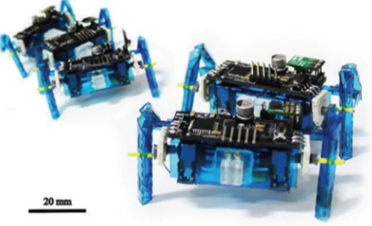
Fig. 1. Soft modular legged robot, SMoLBot.
have challenges regarding design, actuation and power, which affect the body stiffness and maneuvering capabilities.
There are numerous techniques in design and fabrication of miniature robots including 3D printing [2], MEMS fabrica-tion [3], [4] and laser cutting and creating multilayer composite structures with smart composite manufacture (SCM) [5] tech-niques. HAMR [6] and RoACH [7] are examples of such robots fabricated using SCM. Similarly, various types of materials, such as hydro-gels, polymeric elastomers [8] and PET films are used to fabricate small-scale miniature robots. Origami-inspired robot fabrication, which consists of transforming a two dimensional paper sheet to a three dimensional complex design with sub-sequent foldings, is another method to manufacture miniature robots [9], [10]. This method requires laser cutting acetate sheets with an initial robot design that is compatible to be folded into a three dimensional mechanism that serves as the fundamental base structure of the robot body [11]. Soft Modular Legged Robot (SMoLBot), shown in Fig. 1, is a miniature, legged, and modular robot, whose main modules are fabricated by the same method of laser cutting and folding.
Studies on modular robots, classifies them into manual or autonomous re-configurable robots [12]. Both types preserve some advantages of modular robots, including but not limited to modifiable size scale, low weight and low cost production. There have been various studies on self-reconfigurable robots autonomously changing shape to various configurations such as a quadruped or a snake [13], in which each module is provided with computational and communication capability. Similarly, there have been a tendency to use the reconfiguration capabilities
2377-3766 © 2020 IEEE. Personal use is permitted, but republication/redistribution requires IEEE permission. See https://www.ieee.org/publications/rights/index.html for more information.
and electrostatic connections [18]. In a few works, magnetic connections are used in soft complex robots connecting hard driving unit to the soft portion of the robot [19], [20].
Adaptability through mechanical compliance is an inherent advantage of soft robots, however, untethered actuation of soft miniature robots remains a challenge. Prospect of assembling soft and hard units in a modular concept can be a way to overcome challenges regarding actuation and locomotion of the soft robots [21]. Assembling soft and hard units, have granted the possibility of manufacturing bio-inspired robot-designs. For instance, an octopus inspired robot, which locomotes by pushing itself from the sea bed, uses the same modular and soft-hybrid concept to mimic a pattern that is similar to its biological counterpart [22].
Despite the evolution of modular robots, there exists a space for development of a robot which carries features of different classes of robots as to be soft, foldable and modular, simulta-neously. SMoLBot is a foldable modular robot with soft con-nection mechanisms. SMoLBot’s design incorporates a fabrica-tion method, that exploits features of origami inspired foldable robots, such as low weight, low cost, easy to manufacture, high structural integrity and simple replaceable structures. Similarly, with the use of PDMS connection mechanisms, SMoLBot turns to be soft-hybrid and modular at the same time. Each module is made out of a single acetate sheet with optimized fold-locks resulting in a highly resilient assembly, holding motors and electrical components. Each module consists of individually actuated and controlled DC motors, which allows various gait implementations and better locomotion. PDMS backbones make it possible to connect individual modules to each other while having the possibility of imposing different values of stiffness to the system. The contributions of this work are the design of a novel miniature, legged, modular robot that uses a hybrid assembly of soft and origami-inspired structures to improve locomotion, and an experimental study on the locomotion of modular robots with four and six legs with different compliant backbones in a miniature scale.
II. DESIGN OFSMOLBOT
A. Rigid Linkages, Body and Locomotion Design
SMoLBot robot’s modules are folded using 100-micrometer-thick flexible A4 size cellulose acetate sheets. The main struc-tural material, as well as the compliant flexure joint design ap-proach are very similar to other miniature foldable robots such as MinIAQ [11]. In order to increase structural integrity of the body, certain folded structures such as T-folds and tab-and-fastener
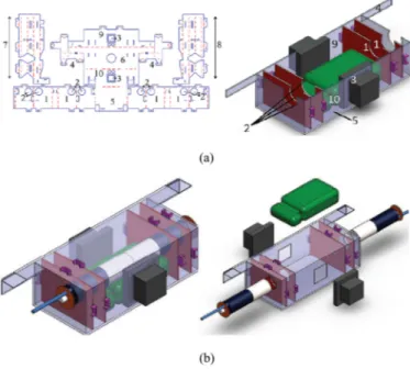
Fig. 2. (a) AutoCad design and cut perspective of a folded robot. T-folds(1), motor housing (2), PDMS lock housing (3), leg locking patch (4), bottom patch and battery housing (5), top patch (6), left leg (7), right leg (8), rear patch (9), front patch (10), fastener and locks (purple), battery (green), PDMS locks (black), leg pin connections (blue), motors (black and grey). (b) Body design out-look and body exploded view.
locking extensions are embedded into the original design. T-folds are out-of-plane extensions that have the capability of stiffening the body frame and acting as a beam between two vertical planes, as shown in Fig. 2. Tab-and-fastener extensions are U shaped fastener tabs, that keep the folded structures locked in place. Combination of rigid T-folds and tab-and-fastener mechanisms reduce the twist and buckling movement of the body. Enough space for two DC motors and a battery housing is embedded between T-folds, and PDMS lock housings are embedded on the vertical stationary planes as shown in Fig. 2(b). Details of the backbone assembly are provided in Section II-B. Getting the smallest robot housing was aimed during the design process. Single module body is approximately in the size of two DC motors (Pololu, Sub-Micro Plastic Plentary Gertmotor) and a single cell 3.7 Volt, 150 mAh Li-Po battery. Two DC motors are placed back-to-back and parallel to each other inside two tight circular openings on the T-folds. Battery is placed just under the motor housing with T-folds holding it in-place (two pairs of T-folds placed inside the body). The battery can easily be accessed through the rear hatch door for charging or removal.
Integrating a mechanism into a design, which has an elliptical trajectory - with a relatively long stride length and large foot lift - and a simple unfolded form for locomotion is a challenge for foldable miniature robots. Leg actuation in SMoLBot is achieved by a four-bar mechanism that is cut and folded from the same sheet used for the body design (Fig. 2(a)). Leg link sizes, position of the joints and the cam shaft (the link connecting the DC motors to the leg) length have been optimized in order to obtain an
Fig. 3. SMoLBot’s four-bar leg mechanism.
TABLE I LEGDIMENSIONS
elliptical trajectory path with maximum contact to the ground and acceptable lift for operation (Fig. 3).
With an initial assumption of known planar coordinates of point A (leg attachment points to the body), point B (motor location) and cam shaft length, kinematic analysis of the leg mechanisms of SMoLBot is conducted in order to determine the unknown parameters such as the positions of points C and E. Determining the unknown coordinates of point C,xc and yc, is done by using known planar coordinates of point A and
D and taking into account that the leg lengths are constant parameters. Finally, unknown coordinates can be found using the set of kinematic equations defined for a four-bar mechanism. Coordinates for point A and B (units are inmm) for the right leg based on a coordinate system on the center of geometry of a single module are as follows:
A = [−8.37, −3.27, −7.50] (1)
B = [+4.16, −3.27, −3.31] (2)
Mirrored parameters of the points A and B with respect to the XZ plane define the A and B values for the left leg. Table I shows the leg constant dimensions of the SMoLBot.
B. Backbone Design and Manufacturing
Backbones can be categorized into three different types, namely: continuous, discrete and hybrid [23]. Robotic systems with continuous backbones (referred as continuum robots) often only use elastic materials for the structural robot parts [24]. Robotic systems with discrete backbones use articulated link-ages as connection mechanisms, and hybrid mechanisms simi-larly utilize a mixture of elastic elements and linkages to achieve a relative motion between the body modules neighboring the backbone.
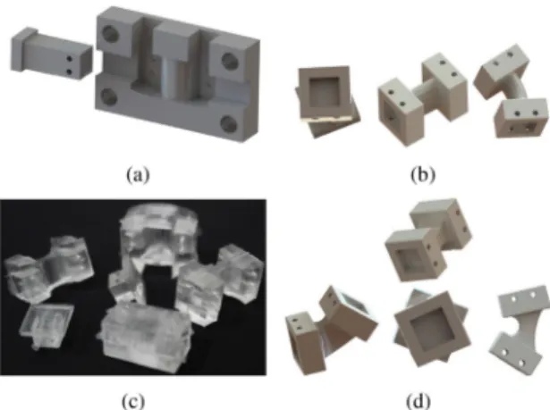
We designed an easy-remove-easy-assemble connection mechanism that can be embedded to the foldable body, using puzzle shaped molds. 3D printed molds with diverse shapes and sizes, based on the backbone’s intended stiffness, have been used in the molding process, an example to such molds
Fig. 4. (a) Compliant(I) backbone mold (b) Compliant(e) backbone and tilted versions (c) PDMS backbones and PDMS locks (d) Compliant(I) backbone and tilted versions.
is shown in Fig. 4(a). Manufacturing backbones with different designs and stiffness values are possible with this fabrication method. Structural and geometrical factors have a great effect on the moment of inertia. The shape of the backbones have been modified as a means to achieve desired stiffness values. We designed and categorized SMoLBot’s backbones based on their overall geometric shapes. Backbones with an elliptical cross-section (compliant(e)) are not rigid but possess a relatively high bending and torsional stiffness values, whereas I-beam type backbones with a rectangular cross-section (compliant(I)) have the smallest bending and torsional stiffness values. The compli-ant(e) and compliant(I) backbones are shown in Fig. 4(b) and (d), respectively. Fig. 4(c) shows different kinds of backbones used in SMoLBot.
Connection assembly consists of two individual pieces, the backbone connecting two individual modules to each other, and the locking mechanism connecting each module to the backbone. PDMS is used for manufacturing both the backbone and the locking mechanism. PDMS locks are fixed inside the modules in order to avoid any undesired movements. Pins are used to fix the PDMS locks to the backbones. This connection mecha-nism between the locks and the backbone makes the lock and backbone mechanism feasible for easy-remove-easy-assemble operation purposes. Slots for these pins have been embedded on both the PDMS lock and the backbone molds during the molding process with circular cuts as shown in Fig. 4. Avoiding any collision between two individual legs on consecutive modules and obtaining intended stiffness characteristics are two main parameters that affect the dimensions of the backbone.
The need to eliminate module collisions set a minimum for the length of the backbone and the desired stiffness values at different axes changes the backbone cross-section shape and dimensions. The initial dimensions of the backbones have been derived using beam stiffness relations with intended stiffness and the Young’s modulus of the PDMS. PDMS Young’s modulus is dependent on its mixing ratio and curing temperature [25], [26]. We have used mixture ratio of 1:5 and 1:10 and curing time of 2 hours at 65◦C temperature [27]. Bending stiffness and torsional
stiffness values for the backbones can be found using (3) and (4):
k = 3EI/L3, (3)
kt= c2Gab3/L, (4)
where E is the Young’s modulus, G is the shear modulus, I is the moment of inertia,a and b are the width, height of the mid-section part of the backbone andL is the backbone’s length. c2is a correction coefficient, reported in [28]. COMSOL analysis have been used in order to obtain stiffness values for the back-bones with complex geometry. The backbone stiffness values are listed in Table II.k1is the torsional stiffness of the backbone, k2andk3are the bending stiffnesses of the backbone along the width and the height of the module. Compliant(e) backbones are I-beam with elliptical mid-cross-section and compliant(I) backbones are I-beams with rectangular cross-sections. Rigid backbones are a solid block of PDMS with metal pin insertions possessing the highest bending and torsional stiffness in all directions.
C. Electronics and Controller
With the intention of independent control and actuation of each module, individual modules all have a printed circuit board (PCB). Each board has the same width and length of a single module. Each module in SMoLBot has two lightweight DC motors that are individually controlled where each is driving one leg. The PCB has an Atmega-328P as the main controller, along with one L293DD motor driver that is placed on the bottom layer. In order to control the speed and position of the DC motors, two position sensors, Bourns Potentiometer 3382 series, are placed on the PCB and connected to the motor shafts with a 3D printed cam shaft. To run the robot, a single cell 3.7 V, 150 mAh LiPo battery is used for each module. Voltage is boosted up to 5 V with a step-up regulator, located on the top layer of the PCB, powering the micro-controller, the motor driver, the sensors and the DC motors.
In order to study the effect of number of legs on miniature modular robot’s locomotion and to conduct experiments with different combination of gaits and backbones, each leg is actu-ated and controlled individually. The signal from each sensor is used to estimate both the frequency and the phase of the motors with respect to each other. Since sensors used in SMoLBot are position sensors with 330◦ output range, motor speeds are calculated at each controller loop with correction parameters to avoid system failure in 30◦ sensor dead range. The controller reference signals consist of two main parameters: desired speed
and position for each motor. Both of these parameters are chosen, based on the gait that is being studied and the desired speed. The electrical connection between different modules are done by usingI2C pins of the micro-controller. Instantaneous value of reference signal generated in the master module is transferred to all remaining modules which are referred as the slave modules. Step-wise process of the control stage can be summarized as follows:
1) Gait chosen by the operator.
2) Desired speed imposed to the system by the operator. 3) Reference signal generated in the master module. 4) Instantaneous reference signal value is transferred in each
control loop to the slave modules.
5) Desired phase differences for each leg are imposed to the legs based on the gait predefined in the code.
6) Motors are individually controlled with PWM signals that are generated for each motor.
Steps 1, 2 and 5 are executed only once in the beginning and their outputs are stored in the main code, remaining steps are continuously executed in each loop for controlling purposes. A PID controller similar to [29] is used to control the motor positions. Reference tracking of two motors with 0 and 180◦ phase (trot gait) can be seen in Fig. 5. Trot gait is a quadruped gait where diagonal legs are in phase and the two side-by-side pair legs are 180◦ apart in phase. Similarly, alternating tripod gait for six legged robots is similar to the trot gait, where the legs on the third module are in phase as the first module legs.
In Fig. 5 dash lines are reference signals with the phase difference equal to 180◦. The results are obtained using serial communication between the Arduino on the PCB and the MAT-LAB, demonstrating the reference signals and the sensors output showing the motor’s real-time positions.
III. FABRICATION ANDASSEMBLY
After finalizing the PCB and soldering the electrical com-ponents, each module is fabricated and assembled. Cellulose acetate sheets are cut with a laser engraver (Universal Laser sys-tems, VLS 3.60) and folded. Body and locomotion mechanisms consist of consecutive foldings of T-folds and tab-and-fasteners, that transform the two dimensional design to a three dimensional complex shape. The next step is placing electronics, DC motors and PDMS locks inside the robot housing and closing and fastening the rear hatches. Then the leg mechanisms are folded and fixed to the body with fasteners provided on the top surface,
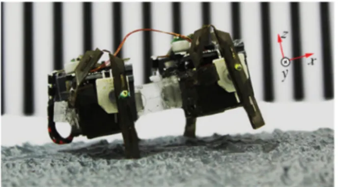
Fig. 6. The rough terrain locomotion of SMoLBot2s. The surface used is a
1 : 10 M scaled version of the NASA Shuttle Radar Topographic Mission 90 M
elevation data for Oregon [30].
separately. The assembly time for each module is about 40 minutes, and folded structure of each module is approximately 16 mm long, 44 mm wide, 15 mm high. Each module is about 18 g in total, 2 g of which is the structural part, 2.5 g DC motors, 5 g battery and 8.5 g that consist of the board and electrical components and pins.
IV. RESULTS ANDDISCUSSION
The first experiments on SMoLBot are designed to observe the effect of backbone‘s stiffness on the smoothness of robot’s locomotion. The experiments are run with two and three mod-ule robots with rigid backbones and elliptical cross-section backbones. The robots are run with trot gait at 2 Hz stepping frequency on smooth and rough surfaces and the roll and pitch angles of the robots, as well as their translational velocities, are compared. A picture of a two-module SMoLBot walking on rough terrain is shown in Fig. 6. Roll and pitch angles of the SMoLBot are defined about the axis parallel to the length (x) and width (y) of the robot; these axes are shown in Fig. 6. Orientation and velocity data are obtained using raw videos showing the robot from side, front, and top. Roll and pitch angles are measured using front and side view videos, respectively. Top-view videos are used to detect the robot’s center of gravity inxy plane and to measure the SMoLBot’s velocity.
The difference of pitch and roll angles of a two module SMoLBot with compliant(e) and rigid backbones can be seen in Figs. 7 and 8, respectively. The two-module robot with compliant(e) backbone (SMoLBot2e) have smoother walking behavior compared to the two-module rigid one (SMoLBot2R) on smooth terrain. The results show that the roll angle variation during locomotion is reduced from 10◦to 7◦and the pitch angle variation decreased from 12◦ to 6◦ switching from the rigid backbone to the compliant one for the SMoLBot2. Two-module robots with compliant backbones conform to the surface better because of the body undulations and the torsion between the two modules, resulting in a smoother locomotion.
The smoother locomotion achieved due to the compliance of the backbones, shows its effects on locomotion speed, as well. Table III shows the linear velocities of two and three-module
Fig. 7. The pitch angle of SMoLBot2on smooth terrain with trot gait.
Fig. 8. The roll angle of SMoLBot2on smooth terrain with trot gait. TABLE III
TRANSLATIONALVELOCITIES
SMoLBots with compliant and rigid backbones on smooth ter-rain. Two-module robots with rigid backbones roll and pitch more compared to the compliant robots. These body rotations result with a difference between the commanded trot gait and the actual gait achieved by the robot because of a lack of touch feedback at the robot’s feet. The compliant backbones allow the robot to conform to the surface better and decrease the difference between the commanded trot gait and the actual achieved gait, resulting in a higher velocity in two-module compliant robots compared to the two-module rigid robots.
Experimental results show that such speed difference between the compliant and the rigid versions does not exist for three module SMoLBots. This speed indifference also supports the hypothesis that the two-module compliant backbone robots have faster locomotion because of the difference between the intended gait and the achieved gait because the gait difference is minimal in three-module robots. Three module SMoLBots operate with an alternating tripod gait, as a result three legs are always in contact with the ground during walking. The tripod configuration results with very small pitch and roll angles, as shown in Fig. 9, therefore the robot’s gait is almost the same as the intended gait. It can also be observed that a smoother locomotion can be
Fig. 9. The pitch and roll angles for SMoLBot3R and SMoLBot3e with alternating tripod gait at 2 Hz stepping frequency on smooth terrain.
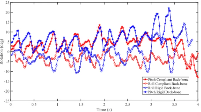
Fig. 10. The roll and pitch angles for SMoLBot2 during rough terrain locomotion.
achieved with six legs rather than four legs. This is rather an expected result, since in a trot gait, a quadruped should be on two feet, but often falls on a third leg forming a tripod, whereas with six legs, the trot gait turn into a statically stable alternating tripod gait. Roll and pitch angles for the six legged robots are reduced compared to the four legged robots. The maximum roll angle is reduced almost from 10◦ to 1◦ and pitch angle decreased from 12◦to 1◦. Similarly, maximum pitch angle for the SMoLBot with the compliant(e) backbone is reduced from 7◦to 4◦. Roll angles for SMoLBot3eand SMoLBot2eare almost equal to each other. This is due to the fact that roll angles for the robots with compliant backbones are mainly dependent on the torsional stiffness of the backbone rather than the number of legs. Torsional stiffness between the modules for SMoLBot3e and SMoLBot2eare equal to each other and constant, which explains the roll angles behavior for SMoLBot3eand SMoLBot2e.
Fig. 10 shows the roll and pitch angles for a two module robot with rigid and compliant(e) backbones on rough terrain. SMoLBot with a compliant backbone shows a slightly smoother locomotion on rough terrain compared to the rigid one. This can be stated by observing the y-range of the red curves and comparing them to the range of blue curves. On the other hand, a secondary observation is made during the rough terrain experiments. Legs on the SMoLBot with compliant backbones face no fatigue issues during the experiments, conversely, legs in rigid backbone experiments faced failure and were changed several times during the experiments. This is due to the sharp
Fig. 11. Two modules schematic with coordinate systems attached on each modules center of gravity and one on the COG of the robot.
changes in the contact force while the legs are hitting the ground and random physical behavior of the rough terrain. The flexible behavior of the soft backbone serves as an impact damper, reducing the effect of sudden and sharp contact forces on the SMoLBot’s legs.
In order to investigate the effect of the number of legs and soft backbones on the miniature modular legged robot’s locomotion, a comprehensive 3D dynamic model demonstrating the loco-motion characteristics in smooth terrain is needed. A dynamic model for ann legged robot with compliant backbones is derived using the Newton-Euler formulation and the contact force model presented in [31]. Equations (5)–(10) define the dynamics of the n legged miniature modular robot in three dimensional space. Fig. 11 represents a schematic of two mid-modules in ann legged robot, whereCCGis the reference frame attached to the center of gravity of the robot andCIis the fixed inertial reference frame attached to the ground.
˙VCG= FCG m − ΩCG× (MVCG) (5) ˙ΩCG= IG−1(MCG− ΩCG× (IGΩCG) − ˙IGΩCG) (6) ˙RI CG= HiI ⎡ ⎢ ⎣ u v w ⎤ ⎥ ⎦ (7) ˙ΘI CG= LIi ⎡ ⎢ ⎣ p q r ⎤ ⎥ ⎦ (8) ˙Ωi
CG=(IMi)−1(MCGi + Mexti + IMi.αCiCG−Ωi×(IMiΩiCG))
(9) ˙ΘI i = LIi ⎡ ⎢ ⎣ pi qi ri ⎤ ⎥ ⎦ (10) In equations (5)–(10)RICG,ΘICG,VCG= [u, v, w], ΩCG= [p, q, r] are position, orientation vector of the robot’s center of gravity (COG) and their rate change, respectively.ΘIi,ΩiCG= [pi, qi, ri] are the orientation vector and the rate change of the
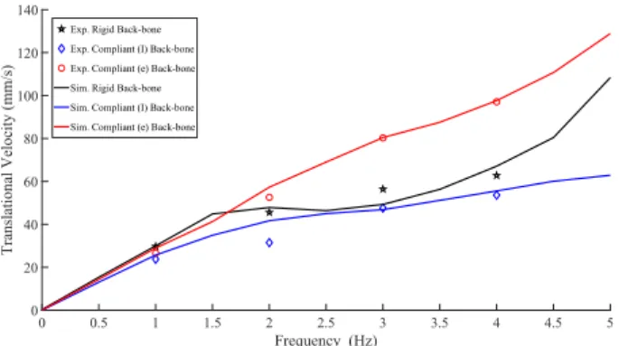
Fig. 12. Experimental and simulation velocity results for SMoLBot2with trot gait over the frequency range of 0–5 Hz on smooth terrain.
orientation vector for each module. FCG and MCG are the
moments acting on the COG of the robot.MCGI are the moments acting on each module with respect to the reference frame on the center of gravity of the module.M and IGare the constant
mass and moment of inertia of the SMoLBot, andIMi is the
moment of inertia of a single module. Mexti are the external
moments due to the backbones.Ωi is the vector sum ofΩiCG andΩiCG, expressed inCi.velocity of each module with respect
to the robot’s center of gravity.αCiCGis the angular acceleration
of the robot’s COG represented in reference frame attached to the modulei (Ci).HiI andLIi are the transformation matrices for vector parameters in accordance with [32].i = [1, 2, . . ., N ] shows the module number, whereN is the number of modules. 12 + 6 × (N − 1) highly non-linear ODEs define the position (7), orientation (8), change rate of position (5), change rate of orientation (6) vectors for the robot’s COG and orientation vector (10) and angular velocity (9) of each module. 12 equations are defining the locomotion parameters for the robot’s COG. Each module added to the robot adds 6 more DOF to the system, as a consequence 6 more ODEs are added to the system of equations defining the locomotion parameters of the modules. Finally, the system of non-linear ODEs is solved using MATLAB’s stiff solverode15 s.
In order to investigate the effect of backbone stiffness on miniature modular legged robot’s locomotion, experiment and simulation results for SMoLBot with two modules are compared as shown in Fig. 12. Velocity results indicate existence of an optimum stiffness value that would make the robot walk with a higher translational velocity within the frequency range of 0–5 (Hz). As Fig. 12 shows, the compliance of the backbone are increasing the linear velocity to some extend; SMoLBot with compliant(e) backbone has higher translational velocity than SMoLBot with rigid backbone.
V. CONCLUSION ANDFUTUREWORK
We are introducing a new soft-hybrid miniature modular robot, SMoLBot, that utilizes the advantages of origami in-spired robots and soft robots at the same time. SMoLBot uses lightweight thin sheets for body and locomotion mechanisms and PDMS as the base material for connection and locking mechanisms. Combination of soft backbones with resilient body
structures in a modular concept results in a robotic system with smoother walking and better maneuverability. SMoLBot2e exploits the advantages of compliant backbones for smoother locomotion on flat terrain by reducing the roll angle from 12◦to 6◦and the pitch angle from 10◦to 7◦. In addition, two module SMoLBots with compliant backbones have higher translational velocities compared to the rigid backbone versions. Moreover, noticeable decrease in robot‘s rotation and increase in robot’s translational velocity have been observed by adding more mod-ules to the SMoLBot, regardless of the backbone’s stiffness.
There will be several studies following this work. Experiment and simulation results show that decreasing the torsional stiff-ness in the backbone reduces the lift of the feet and decreases the robot’s speed. Geometry optimization will be done in order to obtain a geometry with optimum torsion, which result in a higher locomotion speed. A comprehensive study characterizing the be-havior of soft modular robots utilizing compliant backbones, will be conducted. Last but not least, a gait study on SMoLBot with n number of legs will be done in the next steps to characterize locomotion and find the optimized gait forn legged soft-hybrid modular robots.
ACKNOWLEDGMENT
The authors would like to thank Ömer Ba¸sar Özgüven, Talip Batuhan Yılmaz, Mohammad Askari and members of Bilkent Miniature Robotics Laboratory for their invaluable assistance throughout this project.
REFERENCES
[1] R. R. Murphy et al., “Search and rescue robotics,” in Springer Handbook of Robotics. Berlin, Germany: Springer, 2008, pp. 1151–1173.
[2] P. Phamduy, M. A. Vazquez, C. Kim, V. Mwaffo, A. Rizzo, and M. Porfiri, “Design and characterization of a miniature free-swimming robotic fish based on multi-material 3D printing,” Int. J. Intell. Robot. Appl., vol. 1, no. 2, pp. 209–223, 2017.
[3] B. Zhang, J. Qu, and K. R. Oldham, “Experimental evaluation of piezo-electric self-sensing during terrestrial locomotion of a miniature legged robot,” in Proc. IEEE/ASME Int. Conf. Adv. Intell. Mechatronics, 2018, pp. 718–723.
[4] K. Sugita, M. Takato, K. Saito, and F. Uchikoba, “Mechanical structure for high speed locomotion of mems microrobot using SMA rotary actuator,” in Proc. 42nd Annu. Conf. IEEE Ind. Electron. Soc., 2016, pp. 6146–6151. [5] R. J. Wood, S. Avadhanula, R. Sahai, E. Steltz, and R. S. Fearing, “Micro-robot design using fiber reinforced composites,” J. Mech. Des., vol. 130, no. 5, 2008, Art. no. 052304.
[6] O. Ozcan, A. T. Baisch, D. Ithier, and R. J. Wood, “Powertrain selection for a biologically-inspired miniature quadruped robot,” in Proc. IEEE Int. Conf. Robot. Autom., 2014, pp. 2398–2405.
[7] A. M. Hoover, E. Steltz, and R. S. Fearing, “Roach: An autonomous 2.4 g crawling hexapod robot,” in Proc. IEEE/RSJ Int. Conf. Intell. Robots Syst., 2008, pp. 26–33.
[8] M. Sitti, “Miniature soft robotsroad to the clinic,” Nature Rev. Mater., vol. 3, no. 6, pp. 74–75, 2018.
[9] D. Rus and M. T. Tolley, “Design, fabrication and control of origami robots,” Nature Rev. Mater., vol. 3, no. 6, pp. 101–112, 2018.
[10] C. D. Onal, R. J. Wood, and D. Rus, “Towards printable robotics: Origami-inspired planar fabrication of three-dimensional mechanisms,” in Proc. IEEE Int. Conf. Robot. Autom., 2011, pp. 4608–4613.
[11] C. Karakadioglu, M. Askari, and O. Ozcan, “Design and operation of MinIAQ: An untethered foldable miniature quadruped with individually actuated legs,” in Proc. IEEE Int. Conf. Adv. Intell. Mechatronics, Munich, Germany, Jul. 2017, pp. 247–252.
[12] A. Brunete, A. Ranganath, S. Segovia, J. P. de Frutos, M. Hernando, and E. Gambao, “Current trends in reconfigurable modular robots design,” Int. J. Adv. Robot. Syst., vol. 14, no. 3, pp. 1–21, 2017.
[17] K. Gilpin, A. Knaian, and D. Rus, “Robot pebbles: One centimeter modules for programmable matter through self-disassembly,” in Proc. IEEE Int. Conf. Robot. Autom., 2010, pp. 2485–2492.
[18] J. Guo, C. Xiang, and J. Rossiter, “Electrically controllable connection and power transfer by electroadhesion,” Smart Mater. Struct., vol. 28, no. 10, 2019, Art. no. 105012.
[19] S. W. Kwok et al., “Magnetic assembly of soft robots with hard components,” Adv. Functional Mater., vol. 24, no. 15, pp. 2180–2187, 2014.
[20] Z. Chen, C. Zhao, Y. Zhang, Y. Zhu, J. Fan, and J. Zhao, “C-balls: A modular soft robot connected and driven via magnet forced,” in J. Phys.: Conf. Ser., vol. 1207, no. 1, 2019, Art. no. 012006.
[21] A. A. Stokes, R. F. Shepherd, S. A. Morin, F. Ilievski, and G. M. Whitesides, “A hybrid combining hard and soft robots,” Soft Robot., vol. 1, no. 1, pp. 70–74, 2014.
[22] C. D. Onal and D. Rus, “A modular approach to soft robots,” in Proc. 4th IEEE RAS EMBS Int. Conf. Biomed. Robot. Biomechatronics, 2012, pp. 1038–1045.
[27] Z. Wang, A. A. Volinsky, and N. D. Gallant, “Crosslinking effect on poly-dimethylsiloxane elastic modulus measured by custom-built compression instrument,” J. Appl. Polymer Sci., vol. 131, no. 22, 2014.
[28] R. R. Archer, S. H. Crandall, N. C. Dahl, T. J. Lardner, and M. S. Sivakumar, An Introduction to Mechanics of Solids. New York, NY, USA: McGraw-Hill, 2012.
[29] M. Askari, C. Karakadiouglu, F. Ayhan, and O. Ozcan, “MinIAQ-II: A miniature foldable quadruped with an improved leg mechanism,” in Proc. IEEE Int. Conf. Robot. Biomimetics, Macau, China, Dec. 2017, pp. 19–25. [30] MakersBox. (2019) 1:10 m scale of srtm 90 m elevation data with a 10x vertical exaggeration for oregon. [Online]. Available: https://www. thingiverse.com/thing:576849
[31] M. Askari and O. Ozcan, “Dynamic modeling and gait analysis for minia-ture robots in the absence of foot placement control,” in Proc. IEEE Int. Conf. Robot. Autom., Montreal, Canada, May 2019, pp. 9754–9760. [32] R. F. Stengel, Flight Dynamics. Princeton, NJ, USA: Princeton Univ. Press,