Fiber laser-microscope system for
femtosecond photodisruption of
biological samples
Seydi Yavas¸,1,∗Mutlu Erdogan,1Kutan G ¨urel,2F. ¨Omer Ilday,2Y. Burak Eldeniz,3and Uygar H. Tazebay4
1Institute of Materials Science and Nanotechnology, Bilkent University, Ankara, Turkey 06800 2Department of Physics, Bilkent University, Ankara, Turkey 06800
3Electronics Engineering Department, Ankara University, Ankara, Turkey 06100 4Department of Molecular Biology and Genetics, Bilkent University, Ankara, Turkey 06800
Abstract: We report on the development of a ultrafast fiber laser-microscope system for femtosecond photodisruption of biological targets. A mode-locked Yb-fiber laser oscillator generates few-nJ pulses at 32.7 MHz repetition rate, amplified up to ∼125 nJ at 1030 nm. Following dechirping in a grating compressor, ∼240 fs-long pulses are delivered to the sample through a diffraction-limited microscope, which allows real-time imaging and control. The laser can generate arbitrary pulse patterns, formed by two acousto-optic modulators (AOM) controlled by a custom-developed field-programmable gate array (FPGA) controller. This capability opens the route to fine optimization of the ablation processes and management of thermal effects. Sample position, exposure time and imaging are all computerized. The capability of the system to perform femtosecond photodisruption is demonstrated through experiments on tissue and individual cells.
© 2012 Optical Society of America
OCIS codes: (170.7160) Ultrafast technology; (170.1020) Ablation of tissue.
References and links
1. W. Denk, J. H. Strickler and W. W. Webb, “Two-photon laser scanning fluorescence microscopy,” Science 248, 73-76 (1990).
2. P. So, H. Kim and I. Kochevar, “Two-photon deep tissue ex vivo imaging of mouse dermal and subcutaneous structures,” Opt. Express 3, 339–350 (1998).
3. A. Kurella and N. B. Dahotre, “Review paper: Surface Modification for Bioimplants: The Role of Laser Surface Engineering,” J. Biomater. Appl. 20, 5–50 (2005).
4. M. Erdoˇgan, B. ¨Oktem, H. Kalaycioˇglu, S. Yavas¸, P.K. Mukhopadhyay, K. Eken, K. ¨Ozg¨oren, Y. Aykac¸, U.H. Tazebay, F. ¨O. Ilday, “Texturing of titanium (Ti6Al4V) medical implant surfaces with MHz-repetition-rate fem-tosecond and picosecond Yb-doped fiber lasers,” Opt. Express 19, 10986–10996 (2011).
5. A. Vogel, J. Noack, G. H¨uttman, G. Paltauf, “Mechanisms of femtosecond laser nanosurgery of cells and tissues,” Appl. Phys. B 81, 1015–1047 (2005).
6. S. H. Chung, E. Mazur, “Surgical applications of femtosecond lasers,” J. Biophotonics 2, 557–572 (2009). 7. M. F. Yanik, H. Cinar, H. N. Cinar, A. D. Chisholm, Y. Jin and A. Ben-Yakar, “Neurosurgery: functional
regen-eration after laser axotomy,” Nature 432, 822 (2004).
8. L. Sacconi, R. P. O’Connor, A. Jasaitis, A. Masi, M. Buffelli, F. S. Pavone, “In vivo multiphoton nanosurgery on cortical neurons,” J. Biomed. Opt. 12, 050502 (2007).
9. W. Watanabe, S. Matsunaga, T. Shimada, T. Higashi, K. Fukui, K. Itoh, “Femtosecond laser disruption of mito-chondria in living cells,” Med. Laser Appl. 20, 185–191 (2005).
10. J. Colombelli, E. G. Reynaud and E. H. K. Stelzer “Investigating relaxation processes in cells and developing organisms: from cell ablation to cytoskeleton nanosurgery,” Methods Cell Biol. 82, 267–291 (2007).
11. A. L. A. Mascaro, L. Sacconi and F. S. Pavone “Multi-photon nanosurgery in live brain,” Front. Neuroenerget. 2, 21 (2010).
12. P. S. Tsai, P. Blinder, B. J. Migliori, J. Neev, Y. Jin, J. A. Squier and D. Kleinfeld “Plasma-mediated ablation: an optical tool for submicrometer surgery on neuronal and vascular systems,” Curr. Opin. Biotechnol. 20, 90–99 (2009).
13. I. L. Buduno˘glu, C. ¨Ulg¨ud¨ur, B. Oktem, and F. ¨O. Ilday, “Intensity noise of mode-locked fiber lasers,” Opt. Lett. 34, 2516–2518 (2009).
14. K. Murari, Y. Zhang, S. Li, Y. Chen, M.-J. Li, and X. Li, “Compensation-free, all-fiber-optic, two-photon en-domicroscopy at 1.55µm,” Opt. Lett. 36, 1299–1301 (2011).
15. F. Wise, “Femtosecond fiber lasers based on dissipative processes for nonlinear microscopy,” IEEE J. Sel. Top. Quantum Electron. (to be published).
16. A. Chong, J. Buckley, W. Renninger, F. Wise, “All-normal-dispersion femtosecond fiber laser,” Opt. Express 14, 10095–10100 (2006).
17. F. ¨O. Ilday and H. Lim and J. R. Buckley and F. Wise, “Practical all-fiber source of high-power, 120-fs pulses at 1µm,” Opt. Lett. 28, 1362–1364 (2003).
1. Introduction
Ultrashort laser pulses are increasingly used in biological applications in recent years. In ad-dition to their well-known use in nonlinear imaging [1, 2] and medical implant modification [3, 4], manipulation and dissection of individual cells in tissue or structures inside living cells and other biological materials can be accomplished using femtosecond pulses with nanoscale precision [5, 6]. This capability to achieve controlled ablation of cellular structures such as a single axon [7] or dendritic spine [8], sub-cellular organelles such as mitochondria [9] or cytoskeletal elements [10] is also known as nanosurgery. In recent years, various researches have shown that the femtosecond photodisruption technique represents a useful tool for in vivo nanosurgical operations [11, 12]. To date, these experiments have relied on solid state lasers, in particular Ti:sapphire lasers. While these lasers offer good technical performance, they are large in size, costly and very complex. The oscillators operate at a fixed repetition rate around 80 MHz and amplified systems are typically constrained to a few kHz. Control of the repeti-tion rate for an oscillator requires a complex and expensive Pockels cell. External amplificarepeti-tion is even more complex and costly, rendering the master-oscillator power-amplifier (MOPA) ar-chitecture limited in its practical applicability. The necessary pulse durations and energies for these applications are within the range of femtosecond fiber lasers, which are more compact, simpler to operate, and cost much less. Importantly, the repetition rate and the pulse train can be controlled using acousto-optic modulators (AOM). Since the addition of an inline fiber ampli-fier is straightforward, reductions in pulse energy during pulse picking can be compensated for. In addition, the extremely low intensity noise of fiber lasers [13] should relate to the ablation precision. Fiber lasers have been employed in multi-photon imaging [14, 15]. However, despite the clearly high potential, fiber lasers have not been utilized in this area to date.
Here, we report, for the first time to our knowledge, the use of a mode-locked fiber laser for nanosurgery. The custom-developed system is based on a mode-locked Yb-fiber oscilla-tor, seeding a multi-stage fiber amplifier and incorporating a fiber-coupled AOM for repetition rate control, a diffraction grating compressor and a free-space AOM for pulse picking. This enables complete control over the pulse pattern. The laser is coupled to a diffraction-limited fluorescence microscope, with computerized imaging and sample positioning. The utility of the system demonstrated through femtosecond photodisruption experiments.
2. Methods and results
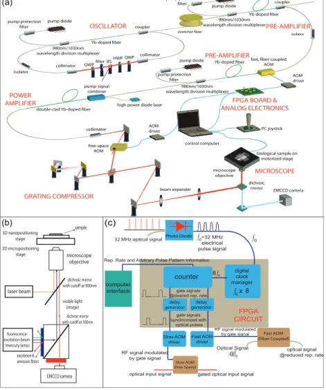
The experimental setup, which comprises of the fiber laser, microscope and custom electronics, is shown schematically in Fig. 1. The seed oscillator is an Yb-doped fiber laser, operating in the all-normal-dispersion regime [16]. The choice of the mode-locked regime was dominated by
the desire to have an extremely robust system. This mode-locking regime results in relatively longer and structured pulses. However, it is the amplifier system that effectively determines the pulse duration as a result of gain narrowing and residual higher-order dispersion [17]. The oscillator incorporates a 5 m-long section of single-mode fiber (SMF, of the type HI-1060) and 0.6 m-long Yb-doped fiber, followed by another 0.4 m of SMF. Net group velocity dispersion, GVDnet, of the oscillator is calculated to be around 0.138 ps2. The gain fiber is pumped in core
with a pump diode delivering 310 mW of power through a 980/1030 nm wavelength division multiplexer. Unidirectional operation is ensured using an in-line optical isolator. Mode-locking is initiated and stabilized by nonlinear polarization evolution. Single pulse operation of the laser output is verified via long-range autocorrelation against bound pulse generation and RF spec-tral measurements (with up to 12 GHz) against regular multiple pulsing. The in-line amplifier system comprises of a fiber stretcher, a fiber-pigtailed AOM, and three gain stages.
pump diode Yb-doped fiber Yb-doped fiber pump diode pump protection filter isolator coupler collimator BS OSCILLATOR Yb-doped fiber 980nm/1030nm wavelength division multiplexer
fast, fiber-coupled AOM coupler isolator PRE-AMPLIFIER PRE-AMPLIFIER POWER AMPLIFIER
double-clad Yb-doped fiber
AOM driver
control computer pump diode
stretcher fiber
high power diode laser pump-signal combiner AOM driver collimator biological sample on motorized stage microscope objective dichroic
mirror EMCCD camera free-space AOM collimator QWP QWP HWP filter beam expander PC joystick laser beam fuorescence excitation beam (mercury lamp) dichroic mirror with cutoff at 900nm dichroic mirror with cutoff at 500nm 2D micropositioning stage 3D nanopositioning stage sample EMCCD camera microscope objective excitation & emission filters visible light (image) (a) (b) 980nm/1030nm wavelength division multiplexer
980nm/1030nm wavelength division multiplexer pump protection
filter
pump protection filter
GRATING COMPRESSOR
FPGA BOARD & ANALOG ELECTRONICS MICROSCOPE (c) Photo Diode f 0 f0 digital clock manager f x 80 8f0 counter computer interface delay generator delay generator Fast AOM driver Slow AOM driver Fast AOM (Fiber Coupled) Slow AOM (Free Space) RF signal modulated by gate signal RF signal modulated by gate signal
optical input signal
optical signal @reduced rep. rate Optical Signal
@ f0 gated optical input signal Rep. Rate and Arbitrary Pulse Pattern Information
gate signals @desired rep. rate
gate signals synchronized with optical pulses 32 MHz optical signal =32 MHz electrical pulse signal FPGA CIRCUIT
Fig. 1. (a) Schematic of the experimental setup. FPGA: field programmable gate array; AOM: acousto-optic modulator. (b) Schematic of the laser-fluorescence microscope optics. (c) Schematic of the FPGA and analog electronic circuitry.
(a)
(b)
(c)
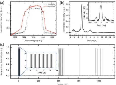
Fig. 2. (a) Optical spectrum of the oscillator and amplifier outputs. (b) Autocorrelation of the amplified pulses after dechirping. Inset: Close-in RF spectrum around the repetition frequency. (c) Measured pulse train, exhibiting a complex pulse sequence as an example. Apparent variations in the pulse heights due to digital sampling are not real.
is delivered through a signal-pump combiner. The lengths of single-mode Yb-doped fibers used for pre-amplifier and amplifier stages are 1.0 m and 0.5 m, respectively. The core diameters are 6µm. First stage is pumped with 300 mW pump power in the forward direction and the second stage is pumped with 120 mW in the backward direction. The final stage comprises of a 2 m-long Yb-doped fiber with 20µm core, 125µm cladding diameters and numerical aperture of 0.08. The gain fiber is pumped in the forward direction with a pump diode laser producing 2 W centered around 976 nm. The beam extracted from the amplifier using a fiber-coupled collimator. The amplified pulses are dechirped in a standard diffraction grating compressor.
The oscillator mode-locks easily and remains mode-locked with the characteristic optical spectrum shown in Fig. 2(a). Low-noise operation is verified by the 80 dB signal-to-sideband suppression as observed through RF spectral measurements (inset of Fig. 2(b)). The oscillator produces 3-ps-long chirped pulses with a bandwidth of 15 nm at a repetition rate of 32.7 MHz. Output coupling from the cavity is achieved through a %20 output coupler, which delivers 32 mW of average power to the fiber stretcher, which consists of 40 m of single mode fiber (HI-1060). Pulses are stretched to ∼35 ps and then amplified to 4.5 nJ energy per pulse in the first amplifier stage. After the first amplifier stage, repetition rate of the pulses are reduced to a desired repetition rate, which can be chosen between 1.02 to 32.7 MHz, depending on the application. The role of the second amplifier stage is to compensate for the power reduction due to pulse picking in the AOM (the insertion loss is ∼4 dB, in addition to losses due to pulse elimination), producing approximately 110 mW of average power, virtually independent of the pulse picking frequency in the AOM. The final power amplifier functions as a power booster to reach pulse energies necessary for ablation of the biological specimens, with a maximum pulse energy of ∼125 nJ, which corresponds to an average power of 500 mW at 4.08 MHz repetition rate. The laser system itself is not limited in average power (with a similar configuration, we
were able to reach 50 W), but in pulse energy by nonlinear effects. It is also indirectly limited in average power by the damage threshold of the microscope objectives. After dechirping in the grating compressor, the compressed pulse duration is approximately 240 fs. The optical spectrum of the chirped, amplified pulses and autocorrelation after dechirping are shown in Fig. 2(a) and (b), respectively. A second, free-space AOM is present for gating of the individual pulses, enabling precise control of the exposure time of the laser on the specimen as well as the further reducing of the repetition rate down to 1 kHz or formation of pulse bursts (Fig. 2(c)).
The pulse picking is handled by an in-house developed FPGA design to pick pulses at two AOMs positioned after the amplifier stages. The FPGA is controlled through a user interface software running on a PC. A portion of the laser signal is detected at a fast photodiode and the output is fed to the FPGA as the clock source. In order to have higher temporal resolution in picking out the optical pulses, a faster clock signal is needed. Thus, the clock signal derived from the repetition rate of the laser, is multiplied by 8 at the digital clock manager inside the FPGA to ∼262 MHz. A one-time-only delay adjustment in the FPGA allows the new clock sig-nal to be fully synchronized to arriving optical pulses at the AOMs. The FPGA starts counting the pulses and sends gating signal to the AOM drivers when a pulse is to be picked. As well as picking out the pulses continuously, the system is capable of working in arbitrary picking mode. The user is able to pick and drop any number of pulses through the software interface, which can be configured to produce a predefined pulse sequence upon the press of a button. There are virtually no limitations on the pulse sequences that can be defined.
For real-time imaging of the biological sample, a customized epi-fluorescent microscope (Nikon Ti-U) is used. A telescope is used to expand the beam, which is directed to the objec-tive with a dichroic mirror housed in an extra turret. The dichroic mirror is highly reflecobjec-tive at the laser wavelength, while transmitting visible light and fluorescence excitation (Fig.1). Sample positioning is accomplished via a 2D micropositioning stage (with a precision of ∼ 1µm) and a 3D piezo stage with ∼20 nm precision. For most applications, the microposi-tioning stage alone provides sufficient resolution. Visualization is based on fluorescent and phase-contrast imaging. A 60X,1.2-NA objective and a 100X, 1.3-NA objective are used in-terchangeably for sub-cellular ablation and a 20X, 0.4-NA, phase-contrast objective is used for multicellular/tissue-level ablation, on both cases, together with a high-sensitivity EMCCD camera for imaging. All major aspects of the laser-microscope system, including control of the FPGA system for pulse picking and gating, positioning of the sample, control of the camera and image acquisition are controlled via a computer for nearly completely hands-free operation. A computer joystick allows ease of use for positioning.
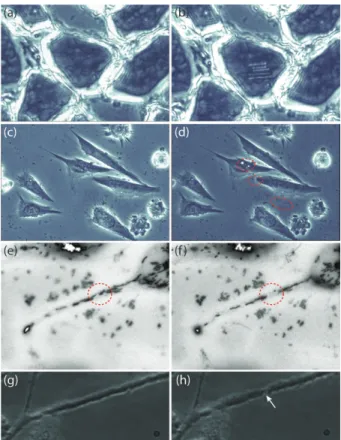
In order to demonstrate the system’s capability to achieve femtosecond photodisruption of biological samples, 240-fs, 7-nJ pulses at 4.08 MHz were used to make cuts on frozen sections of mouse gastrocnemius muscle. The beam was focused to a spot size of ∼ 2.2µm using the
20X objective; the telescope is adjusted to fill the aperture of the 60X and 100X objectives completely, resulting in underfilling of the 20X objective. 5 parallel, linear cuts were made, as shown in Fig. 3(b). The line widths were measured to be 2 − 2.5µm, consistent with the spot
size. Next, femtosecond photodisruption is performed on chemically fixed Saos-2 cells using the 60X objective. In this mode of operation, sub-micron features are obtained (Fig. 3(d)). The system’s capability of targeting single organelle of live Saos-2 cells were examined using the 100X objective. We ablated part of a single mitochondrion (stained with Mitotracker Red 580, Invitrogen) with 2 nJ pulses (Fig. 3(e),(f)). We have ruled against photobleaching, by applying FRAP (fluorescence recovery after photobleach) several hours after the operation. Continuous monitoring of the cell during this time showed that the cell viability was not affected. Finally, we have utilized our system to perform axotomy on differentiated neuroendocrine PC12 cells. An axon of a PC12 cell was damaged with the laser beam with 8 nJ pulse energy at 32.7 MHz
repetition rate (Fig. 3(g),(h)). The procedure interrupted the viability of the cell and after a few minutes wallerian degeneration came up, with prominence of the bead-like structures.
Fig. 3. Tissue slice (mouse gastrocnemius muscle) (a) before and (b) after ablation; 4.08 MHz, 240-fs, 7-nJ. Fixed Saos-2 cells (c) before and (d) after sub-cellular surgery; 4.08 MHz, 240-fs, 7 nJ. (e) Before and (f) after ablation of single mitochondrion stained with Mitotracker Red 580; 4.08 MHz, 240-fs, 2 nJ. (g) and (h) Before and after femtosecond axotomy; 32.7 MHz, 240-fs, 8 nJ. White arrow in (h) indicates the micro-damage.
3. Conclusion
In conclusion, we have demonstrated the use of a custom-built fiber laser-based microscope system for nanosurgery and tissue ablation experiments. Our system constitutes a novel and highly practical instrumentation for ultrafast photodisruption, making maximal use of the ad-vantages offered by fiber technology. The laser system is extremely robust. Through the use of custom FPGA electronics acting through fiber-coupled AOMs, we are able to generate pulse sequence with no limitations (apart from the maximum repetition rate, which is that of the oscil-lator), while the MOPA architecture ensures that the individual pulse energy remains the same. The highly computerized operation of the system paves the way towards automated execution of a sequence of operations on a number of cells. These advantages are obtained at a fraction of the cost of a Ti:sapphire laser, which has traditionally been the system of choice for these experiments. We expect the demonstration of a highly practical and low-cost system will aid the proliferation of ultrafast laser-based ablation experiments in biological sciences.
Acknowledgment