D. Amyot et al. (Eds.): SAM 2014, LNCS 8769, pp. 64–79, 2014. © Springer International Publishing Switzerland 2014
Architecture Framework for Software Safety
Havva Gülay Gürbüz1, Nagehan Pala Er2, and Bedir Tekinerdogan1 1Department of Computer Engineering, Bilkent University, Ankara 06800, Turkey [email protected], [email protected]
2
ASELSAN MGEO, P.O. Box: 30 Etlik, Ankara 06011, Turkey [email protected]
Abstract. Currently, an increasing number of systems are controlled by soft-ware and rely on the correct operation of softsoft-ware. In this context, a safety-critical system is defined as a system in which malfunctioning software could result in death, injury or damage to environment. To mitigate these serious risks, the architecture of safety-critical systems needs to be carefully designed and analyzed. A common practice for modeling software architecture is the adoption of software architecture viewpoints to model the architecture for par-ticular stakeholders and concerns. Existing architecture viewpoints tend to be general purpose and do not explicitly focus on safety concerns in particular. To provide a complementary and dedicated support for designing safety critical systems, we propose an architecture framework for software safety. The archi-tecture framework is based on a metamodel that has been developed after a tho-rough domain analysis. The framework includes three coherent viewpoints, each of which addressing an important concern. The application of the view-points is illustrated for an industrial case of safety-critical avionics control computer system.
Keywords: Software Safety, Safety-Critical Systems, Architectural Modeling, Architecture Design, Architectural Viewpoints.
1
Introduction
Currently, an increasing number of systems are controlled by software and rely on the correct operation of software. In this context, a safety-critical system is defined as a system in which malfunctioning software could result in death, injury or damage to environment. Software can be considered safe if it does not produce an output that causes a catastrophic event for the system. Several methods, processes and models are developed in order to make the software safe. System safety engineering is the appli-cation of engineering and management principles, criteria, and techniques to optimize all aspects of safety within the constraints of operational effectiveness, time, and cost throughout all phases of the system life cycle [8][12].
Designing appropriate software architectures of a safety-critical system is impor-tant to meet the requirements for the communication, coordination and control of the safety-critical concerns. A common practice in the software architecture design
community is to model and document different architectural views for describing the architecture according to the stakeholders’ concerns. An architectural view is a repre-sentation of a set of system elements and relations associated with them to support a particular concern. Having multiple views helps to separate the concerns and as such support the modeling, understanding, communication and analysis of the software architecture for different stakeholders. Architectural views conform to viewpoints that represent the conventions for constructing and using a view. An architectural frame-work organizes and structures the proposed architectural viewpoints. Different archi-tectural frameworks have been proposed in the literature [1][4][5][10].
For modeling the software architecture of safety-critical systems, we can consider the approaches of both the safety engineering domain and the software architecture modeling domain. From the safety engineering perspective, we can observe that many useful models such as fault trees and failure modes and effect analysis have been identified. In addition, several guidelines and patterns have been proposed to support the architecture design of safety critical systems. Unfortunately, the safety engineer-ing domain does not provide explicit modelengineer-ing abstractions for modelengineer-ing the architec-ture of safety-critical systems. On the other hand, existing software architecarchitec-ture frameworks tend to be general purpose and do not directly focus on safety concerns in particular. However, if safety is an important concern, then it is important to provide explicit abstraction mechanisms at the architecture design level to reason about to communicate and analyze the architectural design decisions from an explicit safety perspective. In particular, this is crucial for safety-critical systems which have indeed demanding requirements.
To address the safety concern explicitly and assist the architect, we propose an ar-chitecture framework for modeling arar-chitecture for software safety. The arar-chitecture framework is based on a metamodel that has been developed after a thorough domain analysis. The framework includes three coherent viewpoints, each of which address-ing an important concern. The framework is not mentioned as a replacement of exist-ing general purpose frameworks but rather needs to be considered complementary to these. The application of the viewpoints is illustrated with an industrial case of safety-critical avionics control computer system.
The remainder of the paper is organized as follows. In Section 2, we describe the problem statement in more detail using a real industrial case study. Section 3 presents the metamodel on which the framework is based. Section 4 presents the three view-points of the architecture framework. Section 5 illustrates the application of the framework for the described industrial case study. Section 6 presents the related work and finally Section 7 concludes the paper.
2
Problem Statement
In this section, we describe the general approach for designing safety-critical systems that is adopted in safety engineering practices. For this purpose, we will use an indus-trial case study of an avionics control system project. Based on the case study, we illustrate the need for architecture viewpoints for safety.
The industrial case that we discuss is in the avionics domain. Several reported accidents show that the faults in avionics systems could lead to catastrophic conse-quences that cause loss of life, and likewise we can consider avionics as a safety-critical system. There are several standards, such as the DO-178B [11], used to regulate software development and certification activities for the avionics domain. Usually, avionics control systems have to meet hundreds of requirements related to safety concerns. Table 1 shows an example subset of the requirements that we have selected to describe our case study. In fact, each of these requirements needs to be properly addressed in order to avoid unsafe situations.
Table 1. Requirements of our case study
Requirement Explanation
Display aircraft altitude data
Altitude is defined as the height of the aircraft above sea level. Altitude informa-tion is shown to pilots, as well as, also used by other avionics systems such as ground collision detection system. Pilots depend on the displayed altitude infor-mation especially when landing.
Display aircraft position data
Position is the latitude and longitude coordinates of the aircraft received from GPS (Global Positioning System). Route management also uses aircraft position. Aircraft position is generally showed along with the other points in the route. Pilots can see the deviation from the route and take actions according to the devia-tion.
Display aircraft attitude data
Attitude is defined with the angles of rotation of the aircraft in three dimensions, known as roll, pitch and yaw angles. For instance, the symbol, called as ADI (Attitude Direction Indicator), is used to show roll and pitch angles of the aircraft. Display fuel
amount
Fuel amount is the sum of fuel in all fuel tanks. Fuel amount is generally represented with a bar chart in order to show how much fuel remains in the air-craft.
Display radio frequency channel
The radio frequency channel is used to communicate with ground stations.
In practice, requirements such as those shown in Table 1 are used to identify possi-ble hazards and define safety requirements from possipossi-ble hazards. This overall activi-ty is performed together with domain experts (avionics engineers and pilots), system engineers and safety engineers using several hazard identification methods such as defined in [8]. A hazard is a presence of a potential risk situation that can result or contribute to a mishap. Some of the identified hazards for our case study are given in Table 2 along with possible causes, consequences, severity classification, probability and risk definition. The severity class of the hazards numbered from HZ1 to HZ4 is identified as catastrophic since a possible consequence of these hazards is an aircraft crash. For instance, if a high altitude is displayed instead of its correct value, the pi-lots could assume that the aircraft is high enough not to crash to the ground especially when landing. This assumption could lead to aircraft crash that causes deaths, system loss, and in some cases severe environmental damage. When the consequence of HZ5 is considered, its severity class is identified as negligible because this hazard results in only a communication error with ground station.
Hazard identification is followed by safety requirement identification. For exam-ple, Table 3 lists the safety requirements related with HZ1. Similarly various safety requirements can be defined for the other identified hazards.
Table 2. Hazard identification for the case study
Hazard Possible Causes Cons. Severity Probability Risk
[HZ1]
Displaying wrong altitude data
Loss of/Error in altimeter, Loss of/Error in communica-tion with altimeter, Error in display
Aircraft crash
Catastrophic Improbable Me-dium
[HZ2]
Displaying wrong position data
Loss of/Error in GPS, Loss of/Error in communication with GPS, Error in display
Aircraft crash
Catastrophic Improbable Me-dium [HZ3]
Displaying wrong attitude data
Loss of/Error in gyroscope, Loss of/Error in communica-tion with gyroscope, Error in display
Aircraft crash
Catastrophic Improbable Me-dium
[HZ4]
Displaying wrong fuel amount
Loss of/Error in fuel sensor, Loss of/Error in communica-tion with fuel sensor, Error in display
Aircraft crash
Catastrophic Improbable Me-dium
[HZ5]
Displaying wrong radio frequency
Loss of/Error in radio, Loss of/Error in communication with radio, Error in display
Com- munica-tion error
Negligible Occasional Low
Table 3. Safety requirements derived from HZ1
ID Definition
SR1 Altitude data shall be received from two independent altimeter devices.
SR2 If altitude data can be received from only one altimeter device, the altitude data received shall be displayed and a warning shall be generated.
SR3 If altitude data can be received from neither altimeter device, the altitude data shall not be dis-played and a warning shall be generated.
SR4 If the difference between two altitude values received from two altimeter devices is more than a given threshold, the altitude data shall not be displayed and a warning shall be generated.
SR5 Altitude data shall be displayed on two independent display devices.
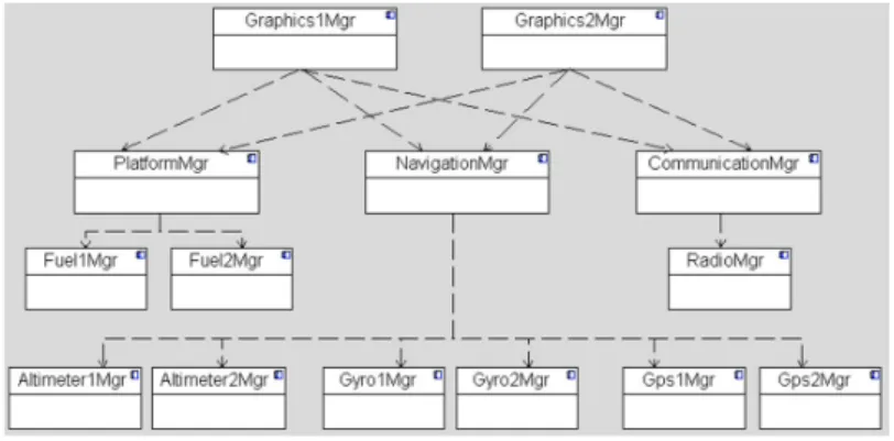
Figure 1 shows the component and connector view [1] of the architecture design of the case study, using a UML component diagram. Altimeter1Mgr and Altimeter2Mgr are the managers of altimeter device 1 and 2, respectively. Each altimeter manager receives the aircraft’s altitude data from the specified altimeter device and provides it to NavigationMgr. Gyro1Mgr and Gyro2Mgr are the managers of gyroscope device 1 and 2, respectively. Each gyroscope manager receives the aircraft’s attitude data from the specified gyroscope device and provides it to NavigationMgr. Gps1Mgr and
Gps2Mgr are the managers of GPS device 1 and 2, respectively. Each GPS manager
receives the aircraft’s position data from the specified GPS device and provides it to
NavigationMgr. Fuel1Mgr and Fuel2Mgr are the managers of fuel sensor 1 and 2,
respectively, and each receives the aircraft’s fuel data from the specified fuel sensor and provides it to PlatformMgr. RadioMgr is the manager of radio device. RadioMgr receives radio frequency data from the radio device and provides it to
Communica-tionMgr. NavigationMgr reads the aircraft’s altitude, attitude and position data from
fuel data from the fuel managers and provides it to graphics managers.
Communica-tionMgr reads radio frequency data from RadioMgr and provides it to graphics
man-agers. Graphics1Mgr and Graphics2Mgr read the aircraft’s altitude, attitude, position, fuel and radio frequency data and show these on the graphics displays.
Fig. 1. Component and connector view of the case study
It should be noted that existing general purpose views including the component and connector view of Fig. 1 do not directly address the safety concerns. For example, the information about whether a component is safety-critical is not explicit. Safety-critical components implement safety-critical requirements but the general purpose views do not answer the question which safety requirements are implemented in which compo-nents. Another missing knowledge is about the tactics and patterns that are applied to handle safety requirements.
The goal of providing safety concerns in views is two-fold: (1) communicating the design decisions related with safety concerns through views (2) accomplishing safety analysis of the architecture from views. The first goal, communicating the design decisions related with safety concerns, is important for safety engineers, system engi-neers and software engiengi-neers. Safety and system engiengi-neers perform hazard identifica-tion and provide safety requirements, a subset of which is allocated to software. Then, the software engineers design and implement the software according to the safety requirements. Thus, these views would help bridge the gap between them by commu-nicating safety information from the safety and system engineers to software engi-neers. The second goal, accomplishing safety analysis of the architecture, supports the safety assessment of the design. If safety-related information can be obtained from the views, the architecture can be properly analyzed. Typically, safety analysis is per-formed from the early stages of the design and the architecture can be updated after safety analysis, if deemed necessary. For example, an important guideline is not to include not-safety-critical software inside safety-critical software. If the safety-critical and not-safety-critical components can be differentiated, such an analysis can be per-formed. After the analysis is accomplished and if there is a safety-critical component which includes not-safety-critical components, then the architecture is reshaped.
To address the safety concerns at the architecture design level, we can now proceed in different ways. We could adopt the guidelines and tactics in the safety engineering
domain to reshape the architecture of Fig. 1 using existing general purpose viewpoint approaches. In this case, all the applied knowledge on safety would be implicit in the architecture and it will be hard to communicate the design decisions and analyze the architecture with respect to safety concerns. In addition to the usage of existing gen-eral purpose viewpoints, we will define a framework that includes explicit viewpoints for addressing safety concerns.
3
Metamodel for Software Safety
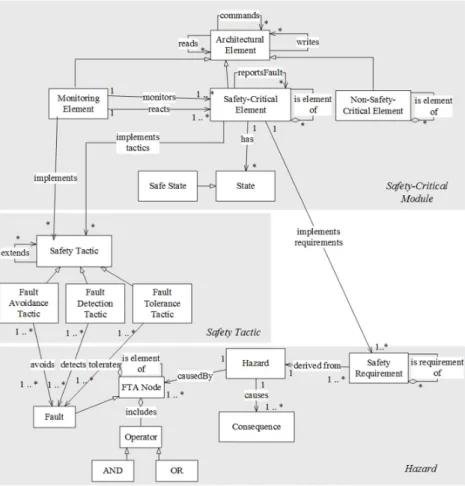
In this section, we provide a metamodel for software safety to represent the safety-related concepts. The metamodel shown in Fig. 2 has been derived after a thorough domain analysis to safety design concepts and considering existing previous studies such as [2][14][17]. The metamodel in Fig. 2 reuses the common concepts of existing metamodels and provides an integrated model. It consists of three parts that form the basis for the architecture viewpoints. The bottom part of the metamodel includes the concepts related to hazards in the system. A Hazard describes the presence of a poten-tial risk situation that can result or contribute to mishap. A Hazard causes some
Con-sequences. Safety Requirements are derived from identified Hazards. We define FTA Node, Operator and Fault to conduct Fault Tree Analysis, which is a well-known
method. Fault Tree Analysis [7] aims to analyze a design for possible faults that lead to hazard in the system using Boolean logic. FTA Nodes, Faults and Operators are the elements of a Fault Tree. Faults are the leaf nodes of the Fault Tree. Operator is used to conduct Boolean logic. Operator can be AND or OR. A Hazard is caused by one or more FTA Nodes.
The middle part of the metamodel includes the concepts related to applied safety tactics in the design. Different studies, such as [3] and [16], have proposed architec-tural tactics or patterns for supporting safety design. In [16], Wu and Kelly propose safety tactics by adopting the SEI’s tactic work. Based on these studies we have iden-tified well-known safety tactics: fault avoidance, fault detection and fault tolerance. The fault avoidance tactic aims to prevent faults from occurring in the system. When a fault has occurred, the fault is detected by applying fault detection tactics. Fault tolerance is the ability of the system to continue properly when the fault has occurred and maintain a safe operational condition. Therefore, applied Safety Tactic can be
Fault Avoidance Tactic, Fault Detection Tactic or Fault Tolerance Tactic in order to
deal with faults.
The top part of the metamodel includes the concepts that present elements in the archi-tecture design. These elements are Monitoring Element, Safety-Critical Element and
Non-Safety Critical Element where Architectural Element is their superclass. An Archi-tectural Element can read data from another ArchiArchi-tectural Element, write data to another Architectural Element, and command to another Architectural Element. Monitoring Element monitors one or more Safety-Critical Elements by checking their status. If there
is a problem in a Safety-Critical Element, it can react by stopping/starting/restarting/ initializing the related Safety-Critical Element. Safety-Critical Element presents the ele-ment that includes safety-critical operations. One Safety-Critical Eleele-ment can be eleele-ment
of another Safety-Critical Element. Safety-Critical Elements can report occurred faults to other Safety-Critical Elements. A Safety-Critical Element has States to
describe its condition. Safe State is one type of the State. If a Fault is detected that can lead to a Hazard and is there is a Safe State that can prevent this Hazard, the
Safety-Critical Element can switch its state to that Safe State. Safety-Safety-Critical Elements
should not include the elements that do not have safety-critical operations. Therefore,
Non-Safety-Critical Element is defined to represent the elements that do not include
safety-critical operations. One Non-Safety-Critical Element can be element of another
Non-Safety-Critical Element. A Monitoring Element or Safety-Critical Element im-plements the Safety Tactics in order to ensure the safety of the system. A Safety-Critical Element can implement one or more Safety Requirements in order to provide
the desired functionality.
4
Viewpoint Definition for Software Safety
Based on the metamodel discussed in the previous section, we derive and explain the viewpoints defined for software safety. We have identified three coherent viewpoints that together form the safety architecture framework: Hazard Viewpoint, Safety
Tac-tics Viewpoint and Safety-Critical Viewpoint.
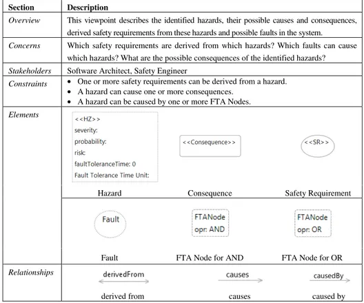
Table 4 shows the Hazard Viewpoint. It aims to support the hazard identification process and shows each hazard along with the fault trees that can cause the hazard, the derived safety requirements and the possible consequences of the hazard.
Table 4. Hazard viewpoint
Section Description
Overview This viewpoint describes the identified hazards, their possible causes and consequences, derived safety requirements from these hazards and possible faults in the system. Concerns Which safety requirements are derived from which hazards? Which faults can cause
which hazards? What are the possible consequences of the identified hazards? Stakeholders Software Architect, Safety Engineer
Constraints • One or more safety requirements can be derived from a hazard. • A hazard can cause one or more consequences.
• A hazard can be caused by one or more FTA Nodes. Elements
Hazard Consequence Safety Requirement
Fault FTA Node for AND FTA Node for OR
Relationships
derived from causes caused by
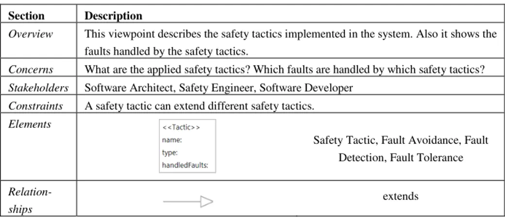
Table 5 presents the safety tactics viewpoint that models the tactics and their rela-tions to cope with the identified hazards. In general we can distinguish among fault avoidance, fault detection and fault tolerance tactics. In the metamodel definition, we define avoids, detects and tolerates relationship from Safety Tactic element to Fault. However, one Fault can be handled by different Safety Tactics, we define an attribute
handledFaults in Safety Tactic element instead of presenting each handled faults as an
element and constructing relationships between Safety Tactics and Faults. This approach improves the readability of the view and shows traceability between Faults and Safety Tactics.
Table 5. Safety tactics viewpoint
Section Description
Overview This viewpoint describes the safety tactics implemented in the system. Also it shows the faults handled by the safety tactics.
Concerns What are the applied safety tactics? Which faults are handled by which safety tactics? Stakeholders Software Architect, Safety Engineer, Software Developer
Constraints A safety tactic can extend different safety tactics. Elements
Safety Tactic, Fault Avoidance, Fault Detection, Fault Tolerance
Relation-ships
extends
Table 6. Safety-critical viewpoint
Section Description
Overview This viewpoint shows the safety-critical elements, monitoring elements, non-safety-critical elements and relations between them. It presents also the implemented safety tactics by related safety-critical elements and monitoring elements. Additionally it shows the implemented safety requirements by related safety-critical elements. Concerns What are the safety-critical elements and their relations? What are the monitoring
ele-ments and relations between monitoring and safety-critical eleele-ments? What are the implemented safety tactics and safety requirements by safety-critical elements and monitoring elements? What are the non-safety-critical elements and their relations? Stakeholders Software Architect, Software Developer, Safety Engineer
Constraints • A safety-critical element can read data from one or more safety-critical elements. • A safety-critical element can write data to one or more safety-critical elements. • A safety-critical element can command one or more safety-critical elements. • A safety-critical element can report fault to one or more safety-critical elements. • A monitoring element can monitor one or more safety-critical elements.
• A monitoring element can stop/start/init/restart one or more safety-critical elements. Elements
Safety-Critical Element Non-Safety-Critical Element Monitoring Element
Relation-ships
reads writes commands
Table 6 explains the safety-critical viewpoint. In the metamodel definition, we de-fine an implements relationship from Monitoring Element and Safety-Critical Element to Safety Tactic. One Safety Tactic can be implemented by different Monitoring
Elements or Safety-Critical Elements. Therefore, we define an attribute implemented-Tactics in both Monitoring Element and Safety-Critical Element instead of showing Safety Tactics as an element in this viewpoint. This modification is also done for the implements relationship between Safety-Critical Element and Safety Requirement.
This relation is shown as an attribute implementedSReqs in Safety-Critical Element.
5
Application of the Architecture Framework
We have applied the viewpoints approach to the case study described in Section 2. The following subsections illustrate the application of defined viewpoints on the case study.
5.1 Hazard View
The hazard view for HZ1 is shown in Fig. 3. Other hazards are excluded for the sake of simplicity. Such a filter can be implemented with a tool. The filter takes the ha-zards as a parameter and shows the faults and safety requirements related only with the specified hazards. This view answers the following questions for our case study. • Which safety requirements are derived from which hazards?
The safety requirements derived from HZ1 are displayed in Fig. 3. These safety re-quirements are defined in Table 3.
• What are the possible consequences of the identified hazards? As shown in Fig. 3, aircraft crash is possible consequence of the HZ1. • Which faults can cause which hazards?
The faults that can cause HZ1 are shown as the leaf nodes of a fault tree generated by using Fault Tree Analysis, which is a well-known method [7]. The faults are num-bered from F1 to F13. Their definitions are given in Table 7. The names of the FTA Nodes are numerated from N1 to N9. N1 and N2 indicate “Loss of Altimeter1” and “Loss of Altimeter2”. N3 and N4 represent “Error in Altimeter1” and “Error in Alti-meter2”. Wrong altimeter data can be displayed when one of the followings occur: when altimeter1 is lost and there is an error in altimeter2 (N5), when altimeter2 is lost and there is an error in altimeter1 (N6), when there is an error in both altimeters (N7) and the difference between them is not greater than the threshold, when there is an error in display device 1 and the graphics manager 2 fails (N8), when there is an error in display device 2 and the graphics manager 1 fails (N9), when the navigation man-ager fails.
Fig. 3. Hazard view for HZ1
Table 7. Fault table
Fault Description Fault Description [F1] Loss of altimeter device 1 [F9] Error in display device 1
[F2] Loss of communication with altimeter device 1 [F10] Error in display device 2
[F3] Loss of altimeter device 2 [F11] Altimeter1Mgr fails
[F4] Loss of communication with altimeter device 2 [F12] Altimeter2Mgr fails
[F5] Error in altimeter device 1 [F13] NavigationMgr fails
[F6] Error in communication with altimeter device 1 [F14] Graphics1Mgr fails
[F7] Error in altimeter device 2 [F15] Graphics2Mgr fails
[F8] Error in communication with altimeter device 2
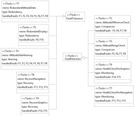
5.2 Safety Tactics View
The safety tactics view shows the tactics implemented in the architecture along with the handled faults. This view answers the question “Which tactics are applied to
han-dle which faults?”. Fig. 4 displays the implemented tactics to hanhan-dle the faults related
with HZ1. Such a filter can be developed within a tool. The filter takes the hazards that the user wants in order to see the tactics to handle the faults that can cause these hazards.
The tactics named T1, T4, T5, T8 and T9 are generated as fault tolerance tactics. T1 is a redundancy tactic for altitude data. Altitude data is received from two different altimeter devices. By applying the tactic T1, the faults from F1 to F8 are handled. T5 is a redundancy tactic for displaying altitude data. Altitude data is displayed on two different displays. The tactic T5 is applied to handle faults F9 and F10. T4 is a
warning tactic for altitude data. An altitude warning is generated when there is a dif-ference between two altitude values received from two different altimeters, or when altitude data is received from only one of the altimeters, or when altitude data cannot be received from both altimeters (different warnings are generated to distinguish these cases). By applying the tactic T4, the faults from F1 to F8 are handled. T8 is a recov-ery tactic for navigation manager. When navigation manager fails, it is recovered. The tactic T8 is applied to handle faults F11, F12 and F13. T9 is a recovery tactic for graphics managers. When one of the graphics managers fails, it is recovered. The tactic T9 handles the faults F14 and F15.
The tactics named T2, T3, T6 and T7 are fault detection tactics. T2 is a comparison tactic and it compares the altitude values received from two different altimeter devic-es and detects if there is a difference. The tactic T2 is applied to handle faults from F5 to F8. T3 is a comparison tactic and it compares the received altitude value with its minimum and maximum values in order to detect out of range altitude value. By ap-plying the tactic T3, the faults from F5 to F8 are handled. T6 is a monitoring tactic that monitors the graphics managers’ failures. The tactic T6 handles the faults F14 and F15. T7 is a monitoring tactic that monitors the navigation manager’s failure. The tactic T7 is applied to handle faults F11, F12 and F13.
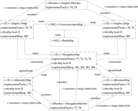
5.3 Safety-Critical View
The safety-critical view for our case study is shown in Fig. 5. The figure shows the related modules with HZ1. A filtering approach can also be applied for this view. Safety-critical modules and their monitors are filtered according to the specified ha-zards. CommunicationMgr and RadioMgr modules are displayed in Fig. 5 in order to show an example of non-safety-critical modules.
As explained in Section 2 the Altimeter1Mgr and Altimeter2Mgr are the managers of the altimeter devices and the Graphics1Mgr and Graphics2Mgr are the managers of the graphics devices. NavigationMgr reads the altitude data from Altimeter1Mgr and Altimeter2Mgr. Graphics1Mgr and Graphics2Mgr read the altitude data from
NavigationMgr. If a warning should be generated NavigationMgr notifies the Graph-ics1Mgr and Graphics2Mgr through commands relation. If a fault is occurred in Alti-meter1Mgr and Altimeter2Mgr, they report the occurred fault to NavigationMgr
through reportsFault relation. NavigationMonitor monitors Altimeter1Mgr,
Altime-ter2Mgr and NavigationMgr. It detects the failure when one of these managers fails
and recovers from failures by stopping/starting/initializing the failed modules. Simi-larly, GraphicsMonitor monitors the Graphics1Mgr and Graphics2Mgr. It detects the failure when one of these managers fails and recovers from failures by
stop-ping/starting/initializing the failed modules.
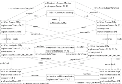
As it can be observed from Fig. 5, NavigationMgr causes single-point of failure that can also be inferred from the fault tree shown in the hazard view in Fig. 3. In this particular case, the identification of the failures is easy to identify, but for more com-plex systems typically component dependency analysis is needed. The analysis of failures and the required design decisions is beyond the scope of this paper since we focus primarily on the modeling of the safety concerns. However, using the architec-tural views both the analysis and design of safety critical systems will be supported. For solving the single point of failure of Fig. 5, we can provide another design alter-native, which is illustrated in Fig. 6. (Note that changing this view also affects hazard and safety tactics views. Since the changes are straightforward, they are not given.) In the second design alternative, (1) redundancy technique is also applied to navigation manager by defining two navigation managers, (2) navigation monitor controls only navigation managers, and (3) a new monitor called AltimeterMonitor is added to con-trol altimeter managers. There are two new tactics implemented by altimeter monitor, which are called as HealthCheckForAltimeter (T10) and RecoverAltimeter (T11). By applying a redundancy tactic for navigation manager, the single-point of failure prob-lem is solved. This design increases the safety of the system. However, addition of the new monitor and manager also increases the relations (function calls) between the related modules and this impacts the performance of the system.
6
Related Work
Various studies [2][14][17] propose a metamodel for safety. Douglas [2] provides a UML profiling for safety analysis including profiling for FTA (Fault Tree Analysis) diagrams. Taguchi [14] provides a metamodel that includes safety concepts expressed with the ISO/FDIS 26262 standard [5] from scratch. In [17], they define a metamodel that includes safety concepts extracted from the airworthiness standard, RTCA DO-178B [11], by extending UML.
In [10], Rozanski and Woods state that quality concerns are crosscutting concerns on the viewpoints and for each quality concern creating a new viewpoint seems less appropriate. Therefore, they propose a concept of architectural perspective that in-cludes a collection of activities, tactics and guidelines that require consideration across a number of the architectural views. In this way, the architectural views pro-vide the description of the architecture, while the architectural perspectives can help to analyze and modify the architecture to ensure that system exhibits the desired quality properties. Rozanski and Woods do not seem to have addressed the safety in their architectural perspective approach.
In our earlier work, we have considered the explicit modeling of viewpoints for quality concerns [13][15]. Hereby, each quality concern, such as adaptability and recove-rability, require a different decomposition of the architecture. To define the required decompositions for the quality concerns, architectural elements and relations are defined accordingly. Earlier work on local recoverability has shown that this approach is also largely applicable. We consider this work complementary to the architectural perspec-tives approach. It seems that both alternative approaches seem to have merits.
Many other different publications have been provided to reason about software safety. But none of these seem to have addressed the solution at a software architec-ture perspective using an integrated set of viewpoints.
7
Conclusion
We have observed that designing a safety-critical system requires to show design decisions related to safety concerns explicitly at the architectural level. Existing viewpoint approaches tend to be general purpose and deliberately do not directly fo-cus on the architectural modeling of software safety concerns. However, in particular for safety-critical systems, it is crucial to represent these concerns early on at the ar-chitecture design level. For this purpose, we have introduced the arar-chitecture frame-work for software safety to address the safety concerns explicitly. The frameframe-work includes three coherent viewpoints, each of which addressing an important concern. The framework with its viewpoints has been developed based on a metamodeling approach, which is a common practice. We did not encounter many problems in de-fining the metamodels, in particular because of the broad knowledge on safety and the reuse of concepts of existing metamodels.
The application of the viewpoints is illustrated for an industrial case on safety-critical avionics control computer system. These viewpoints have formed the basis for analysis and support for the detailed design of the safety-critical systems. Using the viewpoints we could (1) analyze the architecture in the early phases of the development life cycle,
(2) analyze the design alternatives, (3) increase the communication between safety engi-neers and software developers and (4) communicate the design decisions related with safety. We have shown how the architecture framework can be used for a real design of a safety critical system in the avionics domain. The framework appeared indeed to be use-ful to support architecture design of safety critical systems. We have focused on support-ing explicit modelsupport-ing of safety concerns. We believe that with the current framework, the design of safety critical systems can now be better supported. As future work, we will focus on design heuristics to define metrics and develop tools to analyze several design alternatives for safety-critical systems based on the proposed viewpoints.
References
1. Clements, P., Bachmann, F., Bass, L., Garlan, D., Ivers, J., Little, R., Nord, R., Stafford, J.: Documenting Software Architectures: Views and Beyond. Addison-Wesley, Boston (2003)
2. Douglass, B.P.: Analyze System Safety using UML within the IBM Rational Rhapsody Environment. IBM Rational White Paper, IBM Software Group (2009)
3. Gawand, H., Mundada, R.S., Swaminathan, P.: Design Patterns to Implement Safety and Fault Tolerance. International Journal of Computer Applications 18, 6–13 (2011)
4. Hofmeister, C., Nord, R., Soni, D.: Applied Software Architecture. Addison-Wesley, MA (2000)
5. ISO/DIS 26262, Road vehicles - Functional safety. International Organization for Standar-dization, Geneva, Switzerland (2009)
6. Kruchten, P.: The 4+1 View Model of Architecture. IEEE Software 12(6), 42–50 (1995) 7. Leveson, N.G., Harvey, P.R.: Analyzing Software Safety. IEEE Transactions on Software
Engineering 9(5), 569–579 (1983)
8. Leveson, N.G.: Safeware: System Safety and Computers. Addison-Wesley, NY (1995) 9. Meta Object Facility (MOF), http://www.omg.org/mof/
10. Rozanski, N., Woods, E.: Software Architecture Systems Working with Stakeholders Us-ing Viewpoints and Perspectives. Addison-Wesley (2005)
11. RTCA DO-178B, Software Considerations in Airborne Systems and Equipment Certifica-tion (1992)
12. Software Safety Guide Book, NASA Technical Standard, http://www.nasa.gov/ 13. Sözer, H., Tekinerdogan, B., Aksit, M.: Optimizing Decomposition of Software
Architec-ture for Local Recovery. Software Quality Journal 21(2), 203–240 (2013)
14. Taguchi, K.: Meta Modeling Approach to Safety Standard for Consumer Devices. Seminar on Systems Assurance & Safety for Consumer Devices (2011)
15. Tekinerdogan, B., Sözer, H.: Defining Architectural Viewpoints for Quality Concerns. In: Crnkovic, I., Gruhn, V., Book, M. (eds.) ECSA 2011. LNCS, vol. 6903, pp. 26–34. Sprin-ger, Heidelberg (2011)
16. Wu, W., Kelly, T.: Safety Tactics for Software Architecture Design. In: Proceedings of the 28th Annual International Computer Software and Applications Conference, pp. 368–375. IEEE Computer Society, USA (2004)
17. Zoughbi, G., Briand, L., Labiche, Y.: A UML Profile for Developing Airworthiness-Compliant (RTCA DO-178B), Safety-Critical Software. In: Engels, G., Opdyke, B., Schmidt, D.C., Weil, F. (eds.) MODELS 2007. LNCS, vol. 4735, pp. 574–588. Springer, Heidelberg (2007)