Wiels Corner
Naftali (Tull) Hersoovici Lincoln Laboratory - Group 61 Massachusetts institute of Technology 244 WoAod Street
Lexington, MA.02420-9108 USA Tel: +1 (781) 981-0801
Fax: +1 (928) 832-4025 SkypeIAOL: tuliOl
E-mail: [email protected]
Christos Christodoulou Department of Electrical and Computer Engineering University of New Mexico
Albuquerque, NM 87131-1356 USA Tel: +1 (505) 277 6580
Fax: +1 (505) 277 1439 E-mail: [email protected]
Capacity of Printed Dipole Arrays in
the MIMO Channel
Celal Alp Tunc, Defne Aktas, Vakur B. Erturk, and Ayhan Altintas
Department of Electrical and Electronics EngineeringBilkent University
Bilkent, Ankara, TR-06800, Turkey E-mail: [email protected]
Abstract
The performance of printed dipole arrays in the MIMO channel is investigated using a channel model based on the Method of Moments solution of the electric-field integral equation. Comparisons with freestanding dipoles are given in terms of channel capacity. Effects of the electrical properties (such as the dielectric thickness and permittivity) on the MIMO capacity are explored. Various dielectric-substrate configurations yielding high-capacity MIMO arrays are presented.
Keywords: MIMO systems; antenna arrays; microstrip antennas; microstrip arrays; planar printed arrays; antenna array mutual coupling; moment methods
1. Introduction
M
ultiple- input multiple-output (MIMO0) wireless communica-tion systems can increase the data rate in rich scattering environments by using multi-element antenna (MEA) arrays at both the transmitter and the receiver [1, 2]. The choice of the type of multi-element antenna array may significantly affect the wireless channel behavior. Transmitter and receiver antennas must therefore be incorporated into the wireless channel model by including as many electromagnetic effects as possible, in order to have a better system design.Freestanding linear arrays of uniform dipole antennas are fre-quently investigated by incorporating the antenna-coupling effects into the MIMO0 channel [3-7]. However, the performance of printed dipole arrays in MIN40 applications has not been studied as 190
much as the performance of freestanding dipoles, although they have advantages over other antenna types for their low cost, light weight, and ability to conform to the mounting surface.
In this paper, we examine the MIM40 channel capacity of printed dipole arrays. Antenna and electromagnetic effects, such as interactions among the dipoles through space and surface waves and radiated fields, are accurately incorporated into the wireless channel by using the Method-of-Moments (MoM) solution of the electric-field integral equation (EFIE), and by calculating the radiation integrals.
In this work, the channel model used is first benchmarked by both the simulations and measurements of [8] for adaptive free-standing dipole arrays. Ensuring the accuracy of the channel model, the MIMO capacity of printed dipole arrays is explored, and com-parisons with freestanding dipole arrays are given. Furthermore, we IEEE Antennas and Propagation Magazine, Vol. 50, No. 5, October 2008
---investigate the effects of the geometrical and electrical properties of printed arrays (e.g., the dielectric thickness and permittivity, sur-face waves) on the performance in the MIMO channel. Appropriate dielectric-slab configurations, yielding high-capacity printed dipole arrays, are presented. An e'o time convention is used and sup-pressed from the expressions, where wv is the angular frequency.
2. Channel Model with Electric Fields
(MEF)
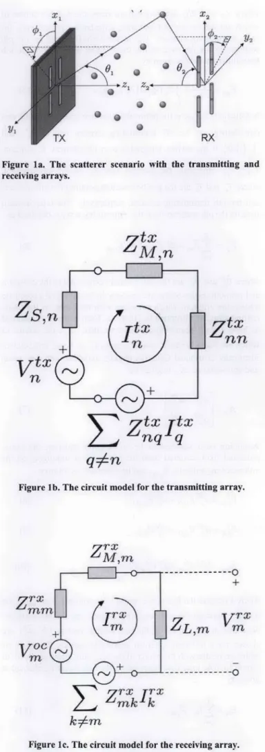
The scattering environment is considered to be a three-dimensional (3D)), single-bounce geometric model, as shown in Figure 1. It assumes a transmitting (TX) and a receiving (RX) array, and S uniformly distributed scatterers. Note that the use of any other geometrical-scatterer scenario, including multi-bounce geometries, is possible, but avoided here for simplicity. Assuming flat fading, the received signal vector, V'~, can be written in terms of the transmitted signal, PE, and the additive white Gaussian noise vector, Wi, with zero mean independent identically distrib-uted (IID) elements with unit variance, as
Figure la. The receiving arrays.
scatterer scenario with the transmitting and
V-h = H IF", + 1T (1)
In Equation (I), H denotes the R x T channel matrix, where R and T are the numbers of antenna elements in the receiving and trans-mitting arrays, respectively. Assuming channel knowledge only at the receiver side, and assuming a diagonal transmission covariance matrix Q =E [ Va (PX) ] =PTI/T = PTII/T, an achievable data rate can be evaluated as
C=E 1092 1+
PT
HHh~
(2)where I is the identity matrix, 1.1 is the matrix determinant, and
PT= E[(PE)h Ft] is the total transmitted signal-to-noise ratio
(SNR), with (.)h and E[.] denoting the conjugate transpose and
expectation operations, respectively. Note that the information-theoretic capacity of this channel under total power constraint PT
is
C=max {E(log,2I+HQHA1)}, QŽto
Tr(Q)!gp-(3)
which is very challenging to compute when H is not from an inde-pendent identically distributed circularly symmetric Gaussian dis-tribution. Tr(.) is the trace operator. As a result, in the rest of the paper, with a slight abuse of the terminology, we will refer to the achievable data rate in Equation (2) as the capacity of the system.
Figure lb shows the circuit model for the nth antenna ele-ment of the transmitting array. The MoM impedance matrix of the transmitting array, Z', relates the currents on the array elements,
P', with the source voltages, V"X, via
q=An
Figure lb. The circuit model for the transmitting array.
Z~rm
+Zr
mm
ZL'm
m
--- 0Z'rk j7
TIX (Z" EXz5+ZS[)-
FtX.
(4)k:Am
Figure Ic. The circuit model for the receiving array. IEEE Antennas and Propagation Magazine, Vol. 50, No. 5, October 200819
ZS,r&
V. *
m
ZtX ItX
nq q
where ZS and Z", are diagonal matrices, the nonzero entries of which are the source and matching impedances, respectively, for each transmitting element. The incident electric field on the pth scatterer in the far zone of the transmitting array due to the nth transmitter antenna is given by
where am is the unit normal vector denoting the polarization direc-tion of the element [9]. Making use of the circuit model of the mth receiver element depicted in Figure 1c, the received signal vector,
F'~, is obtained from the system of linear equations given by
jVrx = ZL
(Zr+Z+ZL)V
-9p= j '""o f.7 (-,,) G (7r.) dr, (5) (12)
In Equation (5), uo is the permeability of free space, j,, is the cur-rent density on the nth transmitting element due to
4,and
J(.)dr'
is the surface integration over the element. In addition, GF,,)represents the Green's function of the environment, where Tpand Y,, are the position vectors pointing the pth scatterer and the nth transmitting antenna, respectively. The total incident field on the pth scatterer from the transmitting array is obtained as'ip=
~Ef
=-P0" 0+ý PEPO (6)n=1 p
whre9 and are the unit normal vectors due to the elevation and azimuth angles of the pth scatterer in the spherical coordinate system the origin of which coincides with the center of the trans-mitting array, as illustrated in Figure la. Each scatterer is assumed to have a 2 x 2 scattering-coefficient matrix, AP, the entries of which are taken, without loss of generality, as being independent identically distributed Gaussian random variables with zero mean and unit variance. AP is given by
Faý
aýAssuming each scatterer to be an isotropic radiator, the cross-polarized field scattered from the pth scatterer impinging on the mth receiving antenna, Epm can be expressed as follows:
0
Vp0=ap0 Ep,, + aft~(8
VP P, (9)
'EP = '4PV00+ ýp V0) -jkrp
where kdenotes the free-space propagation constant, and rp is the distance between the mth receiving element and the pth scatterer. Note that in Equation (10), the unit normal vectors (102p,~ are chosen for a different spherical coordinate system, the origin of which coincides with the center of the receiving array, as shown in Figure Ia. The total field received by the mth receiving element is given by
S
Em. 4am .Epm, (
P=I
192
where Z'~ is the mutual interactions matrix of the receiving array obtained via MoM; ZL and Z' are the load and matching imped-ance matrices, respectively (which are diagonal); and V is the excitation vector of the MoM matrix equation obtained from the total received fields on the receiving elements. The entries of F are evaluated by
(13)
Vm JEm f (n) w.m(r;) drm,
S.'
where Wm is the weighting function over the mth receiver element and is taken as the current distribution on the element (i.e., ,nth testing function) for employing a Galerkin's MoM solution. In order to find the entries of mutual coupling included in H, the fol-lowing procedure is utilized:
1. Evaluate Zt' and Z'~. 2. Start with n =I.
3. Activate the nth TX element (V," = lV, Vkft = 0). 4. Calculate the current vector utilizing Equation (4).
5. Evaluate Equations (5)-(13); the entries of the MIMO channel matrix can then be simply evaluated as
V~f
nk.. (14)
6. Increase n, and go to Step 3.
It should be mentioned that the efficiency of the algorithm is governed by the evaluation of the self and mutual interactions (i.e., the matrix filling time). When the transmitter array is a freestand-ing linear dipole array, the free-space Green's function and piece-wise sinusoidal currents on the dipole elements [9] are used to solve the electric-field integral equation and to generate the imped-ance-matrix entries by applying a Galerkin's MoM solution. The electric field of a single freestanding dipole element is evaluated simply by the closed-form integration of Equation (5).
In the case of printed arrays, different Green's function repre-sentations are used in a computationally optimized manner, based on the distance between array elements [ 10- 14]. The investigation of printed dipole arrays is done utilizing the more-general two-dimensional finite arrays of printed dipoles [10, 11], using a hybrid MoM/Green's function technique. Assuming an ideal delta-gap generator at the terminals of each center-fed dipole and using
7.
6.
~.5.
4.
20 40 60 80 100 120 140 100 180 200
Number of Cost Function Evaluations
Figure 2. The validation of the channel model used, with both the simulations and measurements of [8].
2 Element TX Array
5--C)
Interelement SpainMO
Fiue3. The caaiya fnto fth ne-lmenOpc
mentlmet pcig.1 5; 5 -t--GA [8] -- Measurement [81 MEF with PS0 (FS) 2 Element TX Array 0.5 1
Interelement Spacing [XI
Figure 4. The mutual-coupling effects on the capacity for the two-element array.
3 Element TX Array
0 0.5 1
Interelemnent Spacing
R
1.5
Figure 5. The capacity as a function of the inter-element spac-ing for three-element freestandspac-ing (FS) and printed (PR) dipole arrays with side-by-side (I x 3) and collinear (3 x 1) arrangements.
IEEE Antennas and Propagation Magazine, Vol. 50, No. 5, October 200819
C) C)
Galerkin's MoM solution, entries of the mutual-interactions matri-ces, Z"') are obtained as in [10-13]. The reader may refer to [10-12] for the grounded dielectric slab's Green's function and the electric field of a single printed element in a transmitting array to implement Equation (5).
3. Numerical Results
In this section, numerical results on the MIN40 capacity of printed and freestanding dipole antennas are given. The three-dimensional scattering environment was considered to be formed by 20 uniformly distributed point scatterers, located in a common office room of dimensions 8 mn in length, 3 mn in width, and with a height as in [8]. The capacity results were obtained by averaging the MIMO channel capacity over 1000 different channel realiza-tions.
Freestanding dipole arrays in this work were considered to be formed by thin-wire elements of A/2 in length and 2/200 in radius, whereas printed elements were of Ae /2 in length and A/100 in width, and were placed on top of a dielectric substrate with a dielectric constant of vr and a thickness of d above a ground plane. Note that A is the wavelength in free space, and
X, = 2/[0.5(er ± l)]1/2 is the effective wavelength due to the dielectric material.
3.1 Validation of the Channel Model
In order to check the accuracy of the channel model used, we utilized experimental measurements done in [8] under realistic test conditions. In [8], Migliore et al. devised an adaptive MIN40 (AdaM) system of identical transmitting and receiving arrays offreestanding (FS) dipoles with two active elements surrounded by six parasitic elements. The geometry of the adaptive MIN40 system used was rather simple. Thin-wire dipole antennas were placed in a rectangular lattice of 2 x4 square grids with an edge length of A/4. Active elements were placed in the middle of the lattice, and were 2/2 apart from each other. On the other hand, the parasitic elements were placed so as to surround the lattice. Every antenna element was placed at a height of one meter from the floor. The details of the geometry and the experiment are available in [8]. The termination impedances of the parasitic elements (connected to micro-electromechanical system (MEMS) switches at both the transmitter and receiver) were altered to determine the optimal channel capacity using genetic algorithms (GA). For each configu-ration obtained from the genetic-algorithm evaluations of channel simulations, the channel matrix. H, was measured by employing a vector network analyzer. The transmitted SNR was selected so as to achieve a channel capacity of 4 bits/s/Hz solely with active antennas, and the performance of the adaptive MIMO system was evaluated with this transmitted SNR throughout the simulations and measurements.
Here, the full-wave channel model was utilized to simulate the aforementioned measurement environment, and Particle Swarm Optimization (PS0) [ 15] was employed to find the optimal channel capacity. When modeling the office room in which measurements were made, parameters were set to be the same as those of the
194
measurements of [8]. Under these conditions, the experiment per-formed in [8] was simulated. The results of the channel model in conjunction with PSO are depicted in Figure 2 (represented by "MEF with PS0 (FS)"), along with the measurement and genetic algorithm simulation results of [8]. They were all in very good agreement, which illustrates the validity and accuracy of the MIMO0 channel model used. Figure 2 also shows that for a small number of cost-function evaluations, PS0 could reach higher capacity values than did the genetic algorithm. However, after 80 evaluations, the two optimization algorithms led to approximately the same results.
3.2 Printed Dipoles in the MIMO Channel
For all numerical results presented from this point forward, the following receiver array configuration was used: R - 2 x 2-=4 freestanding dipoles were located in a plane broadside to the transmitter array. Here, 2 x 2 stands for a configuration in the square matrix notation, such that two side-by-side pairs of two col-linear antennas formed the R - 4 element receiving array, as illus-trated in Figure 1. Both the horizontal and vertical spacings between the phase centers of dipoles were set to be 0.75A. The distance between the parallel transmitting and receiving planes was taken to be 7.5 mn. Furthermore, for all the following numerical results, the termination impedances were considered to be 50 0 (i.e., Zs,, ZLm,, 50 Q), and conjugate matching was assumed(i.e., Z. M',n Sý. = 5 0 9 and Z." + Zrx,,= ý.= 0
Also, the transmitted SNR was fixed such that the single-input multiple-output (SIMO) capacity for a single freestanding dipole at the transmitter was 4 b/s/Hz.
In Figures 3-6, the MIMO performance of the printed dipole arrays is compared with that of the freestanding dipoles. For this purpose, the dielectric slab parameters were first selected as er 3 and d - 0.1, yielding approximately the same SIMO capacity of
the freestanding dipole (see Figures 3 and 5). The MIMO capaci-ties of the transmitting arrays of printed (PR) and freestanding (FS) dipoles with both side-by-side (Ilx T) and collinear (T x 1) arrange-ments were then plotted as functions of the inter-element spacing, for T = 2 in Figure 3 and for T = 3 in Figure 5, along with the SIMO capacities.
Inspecting Figures 3 and 5, it can be said that the capacity of freestanding dipoles showed a fluctuating behavior as a function of inter-element spacing, whereas printed dipoles were more stable in that sense. Furthermore, as the number of antenna elements increased, the variation in the capacity rose, particularly for the freestanding dipoles. For both types of dipoles, it was observed that after certain inter-element spacing values, the capacities of side-by-side or collinear arrangements did not significantly differ.
Although not shown here, the inter-element spacing required to exceed the SIMO0 capacity for printed dipoles, Aexceed, depended on the dielectric parameters (more on d than on --,.). For example, for a substrate of c,=3, Axceed=-0.192 when
d=0.12, whereas it became 0.05A when d=0.17A. Thus,
printed arrays with closely spaced elements that have a relatively high capacity can be designed by using appropriate dielectric slabs. However, if the dielectric substrate is not carefully chosen, then Aceed for printed dipoles can be larger than that of the freestand-IEEE Antennas and Propagation Magazine, Vol. 50, No. 5, October 2008
0.51 Interelemnent Spacing[X 1 x3 TX Array 0 C. 0 C.)
Figure 6. The mutual-coupling effects on the capacity for the
three-element array. Figure 8. The capacity as a function of the dielectric thickness.
1x3 TX Array
0. 0
0
0.25
Relative Pe mifttiV4t (Ir ý 0.05 Dilejectrdic Th cness [11 Figure 7. The capacity as a function of the dielectric
permittiv-ity.
Figure 9. The capacity as a function of the dielectric thickness and permittivity for a printed array with three side-by-side dipoles.
IEEE Antennas and Propagation Magazine, Vol. 50, No. 5, October 200815
0 C) 6.3 S6.2 0.)--195
ing dipoles, as seen in Figure 3, resulting in the SIMO0 capacity being better than the MIN40 capacity. This is obviously an
unde-sired situation for designers. Besides, a high MIMO capacity for arrays with elements closely placed can also be obtained by prop-erly adjusting the termination impedances. This was shown in [3, 4] for the freestanding-dipole cases.
The effect of mutual coupling is investigated in Figures 4 and 6 by plotting Cnomc Cm., C,,omc is the capacity obtained ignoring mutual coupling, by setting the off-diagonal elements of the mutual-interactions matrix to zero. CmC is the capacity in the regu-lar (coupled) case. It was observed that printed dipole arrays were less sensitive to mutual coupling than the freestanding dipole arrays, and that coupling can be safely ignored for element separa-tions larger than 0.5A. For the collinear arrangement of printed dipoles, the coupling was mainly due to the surface waves. It should be noted that coupling through surface waves has no sig-nificant effect on the MIM40 channel capacity. The fluctuations for freestanding dipoles were observed for the mutual-coupling effect as well, whereas the curves for printed dipoles were smoother. However, for higher e, values, the Cfl,,. -~C,, results for printed arrays may oscillate slightly, due to increased surface waves.
In order to examine the effect of dielectric constant (er.) on the MM10 performance, the capacity was plotted against varying cr for four different separation values (i.e., A =0.452, 0.52, 0.55A, 0.62) in Figure 7. The thickness of the material was kept at d = 0. 1A. It was seen that increasing c,, slightly raised the
chan-nel capacity, due to increased beamwidth in the azimuth pattern of the printed dipoles [10, 16].
The effect of the dielectric thickness (d) on the capacity is explored in Figure 8. The capacity was plotted as a function of varying d for the same element separations as in Figure 7, while the dielectric constant was kept constant at er = 3. Exceeding certain d values, the capacity curves were observed to be bent. For small d values, the images due the ground plane tended to cancel the effects of dipoles, and hence the capacity was low. Up to certain thickness values, the capacity increased drastically due to increased radiation intensity in both the azimuth and elevation planes. It then started to decay, because of the increased number of surface-wave modes [ 17]. 7Z0.17 )0.16- 0.14-a1) .I) O 0.13- 0.12-0.11 2 2.5 3 3.5 4 4.5 5
Relative Permittivity
(ed
Figure 10. The dielectric thickness and permittivity configura-tions yielding maximum capacity.
198
In Figure 9, the capacity is plotted against varying er and d, while the element separation was kept constant at A= 0.52. The maxima where the capacity curves are bent could be explicitly seen. Note that all the capacity values at these maxima were larger than the largest capacity of the freestanding array. Figure 10 illus-trates the (er, d) configurations yielding the maximum capacity values. A curve with the relation dg,12=ccudbeitdt h configuration data, where c is a constant around 0.26. Note that the fitting-curve relation with c;t 0.26 was found to be valid for other
A values, as well.
4. Conclusions
The MIMO performance of printed dipole arrays was ana-lyzed using a full-wave channel model, based on the Method of Moments solution of the electric-field integral equation. The model was benchmarked by both the simulations and measurements of [8]. Capacity comparisons of printed dipole arrays with freestand-ing (FS) arrays were then given. It was observed that printed dipoles are less sensitive to the mutual coupling than freestanding dipoles in terms of MIMO capacity. Furthermore, the coupling between printed dipoles through surface waves was shown to have no significant effect on the channel capacity.
Effects of the electrical properties of printed dipoles on the MIMO capacity were explored in terms of the relative permittivity and thickness of the dielectric material.
5. Acknowledgments
This work was supported by the Turkish Scientific and Technical Research Agency (TIYWTAK), under Grants EEEAG-106E081, EEEAG-104E044, and EEEAG-105E065; by the Turk-ish Academy of Sciences (TOBA)-GEBIP, and also in part by the European Commission in the framework of the FP7 Network of Excellence in Wireless COMmunications NEWCOM±-i (contract n. 216715).
6. References
1. I. E. Telatar, "Capacity of Multi-Antenna Gaussian Channels," Europ. Trans. Telecommun., 10, November 1999, pp. 585-595. 2. G. J. Foschini and M. J. Gans, "On Limits of Wireless Commru-nications; in a Fading Environment when Using Multiple Anten-nas," Wireless Personal Commun., 6, March 1998, pp. 311-335.
3. J. W. Wallace and M. A. Jensen, "Termination-Dependent Diversity Performance of Coupled Antennas: Network Theory Analysis," IEEE Transactions on Antennas and Propagation, 52, 1, 2004, pp. 98-105.
4. J. W. Wallace and M. A. Jensen, "Mutual Coupling in MIM40 Wireless Systems: A Rigorous Network Theory Analysis," IEEE
Transactions on Wireless Communications, 3, 4, 2004, pp. 1317-1325.
5. T. Svantesson and A. Ranheim, "Mutual Coupling Effects on the Capacity of Multielement Antenna Systems," Proc. IEEE Int. Conf. Acoustics, Speech, and Signal Processing (ICASSP '01), Salt Lake City, UT, May 2001, pp. 2485-2488.
6. R. Janaswamy, "Effect of Element Mutual Coupling on the Capacity of Fixed Length Linear Arrays," IEEE Antennas and Wireless Propagation Letters, 1, 1, 2002, pp. 157-160.
7. M. Bialkowski, P. Uthansakul, K. Bialkowski, and S. Durrani, "Investigating the Performance of MIMO Systems from an Elec-tromagnetic Perspective," Microwave and Optical Technology
Letters, 48, 7, July 2006, pp. 1233-1238.
8. M. D. Migliore, D. Pinchera and F. Schettino, "Improving Channel Capacity Using Adaptive MIMO," IEEE Transactions on Antennas and Propagation, AP-54, November 2006, pp. 348
1-3489.
9. C. A. Balanis, Antenna Theory: Analysis and Design, Third
Edition, New York, John Wiley & Sons, 2005.
10. D. M. Pozar, "Analysis of Finite Phased Arrays of Printed Dipoles," IEEE Transactions on Antennas and Propagation, A.P-33, 1985, pp. 1045-1053.
11. 0. Bakir, "Investigation of Finite Phased Arrays of Printed Antennas on Planar and Cylindrical Grounded Dielectric Slabs," Master's thesis, Bilkent University, Ankara, Turkey, 2006, avail-able at http://www.thesis.bilkent.edu.tr/0003095.pdf.
12. M. Marin, S. Barkeshli, and P. H. Pathak, "Efficient Analysis of Planar Microstrip Geometries Using a Closed-Form Asymptotic Representation of the Grounded Dielectric Slab Green's Function," IEEE Transactions on Microwave Theory and Techniques, 37, April 1989, pp. 669-679.
13. D. M. Pozar, "Input Impedance and Mutual Coupling of Rec-tangular Microstrip Antennas," IEEE Transactions on Antennas
and Propagation, AP-30, November 1982, pp. 1191-1196. 14. 0. Bakir, 0. A. Civi, V. B. Ertfirk, and H.-T. Chou, "Efficient Analysis of Phased Arrays of Microstrip Patches Using a Hybrid Generalized Forward Backward Method/Green's Function Tech-nique with a DFT Based Acceleration Algorithm," IEEE Transac-tions on Antennas and Propagation, AP-56, 6, June 2008, pp.1669-1678.
15. J. Robinson and Y. Rahniat-Samii, "Particle Swarm Optimiza-tion in Electromagnetics," IEEE Transactions on Antennas and
Propagation, AP-52, February 2004, pp. 397-407.
16. H. Nakano, K. Hirose, T. Suzuki, S. R. Kerner, and N. G. Alexopoulos, "Numerical Analyses of Printed Line Antennas," Microwaves, Antennas and Propagation, JEE Proceedings H, 136,
2, 1989, pp. 98-104.
17. P. Katehi and N. Alexopoulos, "On the Effect of Substrate Thickness and Permittivity on Printed Circuit Dipole Properties," IEEE International Symposium on Antennas and Propagation Digest, May 1982, pp. 70-73.
Introducing the Authors
Celal Alp Tuuc received the BSc in Electronics and Communication Engineering from Istanbul Technical University, Istanbul, in 2001, and his MSc in Electrical and Electronics Engi-neering from Bilkent University, Ankara, in 2003. He is currently a PhD student and research assistant in the same department. His research areas are numerical techniques for computational electro-magnetics, large-scale electromagnetic radiation scattering prob-lems, and antennas and propagation for MIMO wireless communi-cations. Celal Alp Tunc was a recipient of the Young Scientist Award of UTRSI in 2008. He is a congress member of Besiktas JK, and married to Ilknur.
Defnie Aktas received the BS from Middle East Technical University, Ankara, Turkey, in 1996, and the MS and PhD from The Ohio State University, Columbus, in 1998 and 2002, respec-tively, all in Electrical Engineering. She is currently an Assistant Professor in the Department of Electrical and Electronics Engi-neering at Bilkent University, Ankara, Turkey. Before joining Bilkent University, she was a Research Fellow at the University of Melbourne, Melbourne, Australia, and a Postdoctoral Researcher at The Ohio State University. Dr. Aktas is a recipient of the European Commission Marie Curie Fellowship. Her research interests are in physical-layer aspects of wireless communication systems, with emphasis on coding and information-theoretic analysis of multiple-input multiple-output (MIMO) systems.
Vakur B. Ertfirk received the BS in Electrical Engineering from the Middle East Technical University, Ankara, Turkey, in 1993, and the MS and PhD from The Ohio State University (051)), Columbus, in 1996 and 2000, respectively. He is currently an Associate Professor with the Electrical and Electronics Engineer-ing Department, Bilkent University, Ankara. His research interests include the analysis and design of planar and conformal arrays, active integrated antennas, scattering from and propagation over large terrain profiles, as well as metamaterials. Dr. ErlIirk served as
the Secretary/Treasurer of the IEEE Turkey Section as well as the Turkey Chapter of the TEEE Antennas and Propagation, Micro-wave Theory and Techniques, Electron Devices, and Electromag-netic Compatibility Societies. He was the recipient of the 2005 UIRSI Young Scientist Award and the 2007 Turkish Academy of Sciences Distinguished Young Scientist Award.
Ayhan Altintas received his BS and MS degrees from the Middle East Technical University (METU), Ankara, Turkey, in 1979 and 1981, respectively, and the PhD from The Ohio State University, Columbus, in 1986. From 1981 to 1987, he was with the ElectroScience Laboratory, The Ohio State University. He is currently Professor and Chair of Electrical Engineering at Bilkent University, Ankara, Turkey. He has held research fellow and guest professor positions at Australian National University, Canberra, Australia; Tokyo Institute of Technology, Japan; Technical Univer-sity of Munich, Germany; and Concordia UniverUniver-sity, Montreal, Canada. His research interests include high-frequency and numeri-cal techniques in electromagnetic scattering and diffraction, propa-gation modeling and simulation, and fiber and integrated optics.
Dr. Altintas was the Chair of the IEEE Turkey Section for the terms 1991-1993 and 1995-1997. He has also served in many uni-versity committees, and was the Associate Provost of Bilkent Uni-versity for 1995-1998. He is the founder and first Chair of the IEEE AP/MTT Chapter in the Turkey Section. At present, he is the National Chair of URSI Commission B. Dr. Altintas is a Fulbright Scholar, and an Alexander von Humboldt Fellow. He received the ElectroScience Laboratory Outstanding Dissertation Award of 1986, IEEE 1991 Outstanding Student Branch Counselor Award, 1991 Research Award of Prof. Mustafa N. Parlar foundation of METU, and Young Scientist Award of Scientific and Technical Research Council of Turkey (Tubitak) in 1996. He is a recipient of the IEEE Third Millennium Medal. Dr. Altintas is a member of Sigma Xi and Phi Kappa Phi. '
198 IEEE Antennas and Propagation Magazine, Vol. 50, No. 5, October 2008
![Figure 2. The validation of the channel model used, with both the simulations and measurements of [8].](https://thumb-eu.123doks.com/thumbv2/9libnet/5621575.111355/4.915.38.895.28.811/figure-validation-channel-model-used-simulations-measurements.webp)


