REPRESENTING INFORMATION FLOW
IN BUILDING DESIGN PROCESS
USING THE PARAMETER-BASED
DESIGN STRUCTURE MATRIX
A THESIS SUBMITTED TO
THE INSTITUTE OF ECONOMICS AND SOCIAL SCIENCES OF BİLKENT UNIVERSITY
IN PARTIAL FULFILLMENT OF THE REQUIREMENTS FOR THE DEGREE OF
DOCTOR OF PHILOSOPHY IN ART, DESIGN AND ARCHITECTURE
By
Şule Taşlı Pektaş September, 2003
I certify that I have read this thesis and that in my opinion it is fully adequate, in scope and in quality, as a thesis for the degree of Doctor of Philosophy in Art, Design and Architecture.
Prof. Dr. Mustafa Pultar (Supervisor)
I certify that I have read this thesis and that in my opinion it is fully adequate, in scope and in quality, as a thesis for the degree of Doctor of Philosophy in Art, Design and Architecture.
Prof. Dr. Can Baykan
I certify that I have read this thesis and that in my opinion it is fully adequate, in scope and in quality, as a thesis for the degree of Doctor of Philosophy in Art, Design and Architecture.
Assoc. Prof. Dr. Halime Demirkan
I certify that I have read this thesis and that in my opinion it is fully adequate, in scope and in quality, as a thesis for the degree of Doctor of Philosophy in Art, Design and Architecture.
Assoc. Prof. Dr. Ali İhsan Ünay
I certify that I have read this thesis and that in my opinion it is fully adequate, in scope and in quality, as a thesis for the degree of Doctor of Philosophy in Art, Design and Architecture.
Assist. Prof. Dr. Burcu Şenyapılı Approved by the Institute of Fine Arts
ABSTRACT
REPRESENTING INFORMATION FLOW IN BUILDING DESIGN PROCESS USING THE PARAMETER-BASED DESIGN STRUCTURE
MATRIX
Şule Taşlı Pektaş
Ph.D. in Art, Design, and Architecture Supervisor: Prof. Dr. Mustafa Pultar
September, 2003
The Architecture/Engineering/Construction (AEC) industry is one of the multidisciplinary domains in which collaboration among related parties is of utmost importance. Despite the intense flow of information between design professionals, there is a lack of research to better understand and manipulate these flows. Most of the current process modeling tools in the AEC industry do not enable analyses of iterative information cycles. Moreover, these tools represent the process at high levels, thus, they are inappropriate for multi-parameter problems like building design. With a view to alleviate these problems, this thesis introduces the use of parameter-based design structure matrix as a process modeling and system analysis tool for building design. The method reveals insights into the process structure, optimum sequence of parameter decisions, iterative cycles and concurrency in the process. A framework for parameter-based DSM applications in building design is proposed and the application of the framework is demonstrated through two case studies on real life building design problems.
ÖZET
YAPI TASARIM SÜREÇLERİNDE BİLGİ AKIŞLARININ PARAMETRE ESASLI TASARIM YAPISI MATRİSİ YÖNTEMİYLE MODELLENMESİ
Şule Taşlı Pektaş
Güzel Sanatlar, Tasarım, ve Mimarlık Fakültesi Doktora Çalışması
Tez Yöneticisi: Prof. Dr. Mustafa Pultar Eylül, 2003
Yapı sektörü, değişik meslek gruplarının birlikte çalışmasının çok önemli olduğu disiplinler arası alanlardan biridir. Yapı tasarım sürecinde katılımcılar arası yoğun bir bilgi akışı olmasına rağmen, bu akışlar yeterince araştırılmamıştır. Yapı endüstrisinde şu anda kullanılmakta olan pek çok süreç modelleme aracı tasarımdaki döngüsel bilgi akışlarının analizine olanak vermemektedir. Ayrıca, bu araçlar tasarım sürecinin sadece üst seviyelerde modellenmesini sağlamakta, dolayısıyla yapı tasarımı gibi pek çok parametre içeren bir alanda etkinlikleri yetersiz kalmaktadır.
Bahsedilen sorunları çözmek amacıyla, bu tezde parametre esaslı tasarım yapısı matrisi yöntemi yapı tasarımı için bir sistem analizi ve süreç modellemesi aracı olarak önerilmektedir. Önerilen yöntem, tasarım sürecinin yapısı, parametre kararlarının sırası, döngüsel bilgi akışları ve eşzamanlılık konularında bilgi üretmektedir. Yöntemin yapı tasarımında kullanılması için bir çerçeve geliştirilmiş ve önerilen çerçeve iki alan çalışmasında gerçek yapı tasarımı sorunlarına uygulanmıştır. Anahtar Kelimeler: Disiplinler arası Yapı Tasarımı, Tasarım Entegrasyonu, Tasarım Süreç Modelleri, Bilgi Akışı, ve Parametre
ACKNOWLEDGEMENTS
Foremost, I would like to thank my supervisor, Prof. Dr. Mustafa Pultar for his invaluable support and tutorship. He always encouraged me to take an interdisciplinary approach in both design and research which shaped the evolution of this dissertation. Secondly, I would like to thank my dissertation committee members, Assoc. Prof. Dr. Halime Demirkan and Assoc. Prof. Dr. Ali İhsan Ünay who made valuable comments on this study in the supervisory committee meetings.
The design professionals who provided input for the case studies were Kutsi Şamlı (architect), Zafer Kınacı (structural engineer), İhsan Taşeli (mechanical engineer), Nihat Akay (electrical engineer), and Atakan Ogan (OTIS). I thank them very much for their time and support. Besides information on the design processes they undertake, these professionals provided valuable comments on the application of the method in the construction industry which guided me in developing application proposals.
Finally, I would like to thank my family for their love, encouragement, and support. My husband Sait Emre Pektaş always helped and
encouraged me. I am also grateful to my mother Şükran Taşlı and my father Mustafa Taşlı for their continuous support during my education.
TABLE OF CONTENTS
SIGNATURE PAGE ... ii ABSTRACT...…….iii ÖZET... …iv ACKNOWLEDGEMENTS... v TABLE OF CONTENTS...viLIST OF TABLES ...xii
LIST OF FIGURES ... xiii
1. INTRODUCTION ... 1
1.1 Problem Statement ... 1
1.2 Thesis Objectives... 4
1.3 Structure of the Thesis... 5
2. COLLABORATIVE DESIGN RESEARCH IN THE CONSTRUCTION INDUSTRY ... 8
2.1 Definitions of the General Terms ... 10
2.2 Approaches to Collaboration Research ... 12
2.2.1 Educational Approaches ... 12
2.2.2 Studies of Communication and Negotiation ... 13
2.2.3 Information Modeling Approach ... 14
2.2.3.1 Information Related Problems in the Construction Industry . 15 2.2.3.2 What is a Model? ... 19
2.2.3.4 Types of Information Models... 20
3. PROCESS MODELS OF DESIGN ... 23
3.1 Descriptive Generic Frameworks... 23
3.1.1 Design Methods Models ... 23
3.1.2 The RIBA Plan of Work... 24
3.1.3 The Generic Design and Construction Process Protocol ... 25
3.2 Formal Activity Models... 27
3.2.1 Network Models ... 28
3.2.1.1 PERT/CPM ... 28
3.2.1.2 Petri Nets ... 29
3.2.1.3 Data Flow Diagrams ... 31
3.2.1.4 IDEF0... 32
3.2.2 Entity-Relationship Diagrams... 35
3.2.3 Unified Modeling Language ... 37
3.2.4 Activity-based DSM... 38
3.3 Conventional/Empirical Methods ... 39
3.4 Shortcomings of Current Building Design Process Models... 40
4. DESIGN STRUCTURE MATRIX METHOD ... 42
4.1 Description of the Method ... 42
4.1.1 DSM Operations ... 43
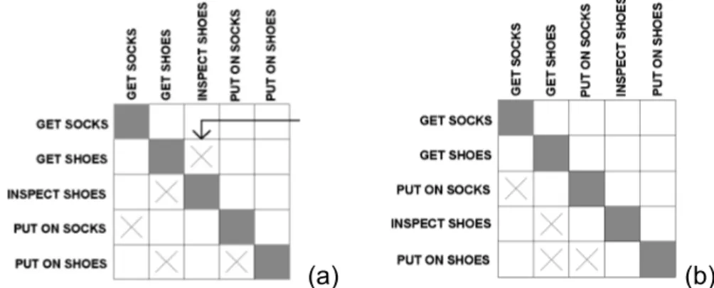
4.1.2 A Simple DSM Example... 45
4.1.3 Building and Using a DSM ... 47
4.2 DSM Types and Applications... 49
4.2.2 Team-based DSM... 51
4.2.3 Activity-based DSM... 53
4.2.4 Parameter-based DSM ... 55
4.2.5 Variations on the Basic DSM Method ... 59
4.2.6 DSM Applications in the Construction Industry ... 63
4.3 DSM Tools ... 66
4.3.1 Standalone Programs ... 66
4.3.2 Web-based Tools... 67
5. PARAMETER-BASED DSM FOR BUILDING DESIGN ... 69
5.1 Underlying Paradigms... 69
5.1.1 Design Methods Research Tradition... 69
5.1.2 Lean Design... 71
5.2 Expected Benefits... 72
5.2.1 Process Improvement ... 73
5.2.1.1 Iteration Management ... 73
5.2.1.2 Common Understanding of a Process ... 77
5.2.1.3 Concurrent Engineering ... 79
5.2.2 Process Integration ... 80
5.2.3 Other Information Processing Applications ... 83
5.3 A Knowledge Management Framework for Parameter-based DSM 84 5.3.1 Assumptions and Scope of the Proposed Model ... 86
5.3.2 The Need for Explicit Definition of Parameters and Industry Foundation Classes ... 87
5.3.3.1 Classification According to Building Parts... 93
5.3.3.2 Classification According to Parent Activities ... 95
5.3.3.3 Classification According to Information Ownership ... 96
5.3.3.4 Classification According to Information Content... 96
5.3.4 Dealing with Large DSM Models... 101
5.3.5 Complementary Use of IDEF0 and DSM ... 103
5.3.6 Implications for Implementation Using Information Technology105 6. CASE STUDY 1: SUSPENDED CEILING DESIGN... 109
6.1 Introduction to the Case Studies... 109
6.2 Suspended Ceiling System Architecture... 113
6.3 Suspended Ceiling Design Process... 116
6.4 Analyzing Suspended Ceiling Design Process with DSM ... 119
6.4.1 Research Setting ... 119
6.4.2 The Project ... 120
6.4.3 Objectives of the Analysis... 124
6.4.4 The Procedure ... 125
6.4.4.1 The Design Configuration ... 126
6.4.4.2 Data Collection... 126
6.4.4.3 The IDEF0 Models ... 128
6.4.4.4 The Information Database ... 135
6.4.4.5 Production of the Matrix and Analyses... 137
6.5 Results and Discussion... 144
6.5.1 Observations on Suspended Ceiling System Interface Design 144 6.5.2 Observations on Suspended Ceiling Assembly Design ... 147
6.5.3 A Comparison between the Assembly Level DSM and the System
Level DSM ... 148
7. CASE STUDY 2: ELEVATOR DESIGN ... 153
7.1 Introduction ... 153
7.2 Elevator System Architecture... 153
7.3 Elevator Design Process... 157
7.4 Analyzing Elevator Design Process with Parameter-based DSM .. 160
7.4.1 Research Setting ... 160
7.4.2 The Scope and Limitations of the Model... 161
7.4.3 Objectives of the Analysis... 162
7.4.4 The Procedure ... 162
7.4.4.1 Data Collection... 163
7.4.4.2 The IDEF0 Models ... 164
7.4.4.3 The Information Database ... 171
7.4.4.4 Production of the Matrix and Analyses... 171
7.5 Results and Discussion... 175
8. DISCUSSION AND CONCLUSIONS... 179
8.1 Implications on the Design Process drawn from the Case Studies 179 8.2 Conclusions ... 183
8.2.1 Contributions of the Study to the Subject Field ... 183
8.2.2 Challenges of the Proposed Method... 185
8.2.2.1 Data Collection... 186
8.2.2.2 Data Representation ... 187
8.3 Suggestions for Further Research ... 189
REFERENCES ... 191
APPENDIX A ... 203
A.1 Classification of Building Parts in UNIFORMAT II ... 204
A.2 A Classification of Building Design Performance Factors... 205
APPENDIX B ... 207
B.1 Suspended Ceiling Design Parameter Definitions... 208
B.2 Elevator Design Parameter Definitions... 212
APPENDIX C ... 217
C.1 A Computer Program For Building the Design Structure Matrix .... 218
C.2 A Computer Program For Partitioning and Banding the Design Structure Matrix ... 223
LIST OF TABLES
Table 3.1: An Overview of the RIBA Plan of Work... 25
Table 4.1: A Taxonomy of System Element Interactions ... 50
Table 4.2 Example of a Spatial Interaction Quantification Scheme ... 51
Table 4.3 A Taxonomy for Information Flows in a Team-based DSM... 52
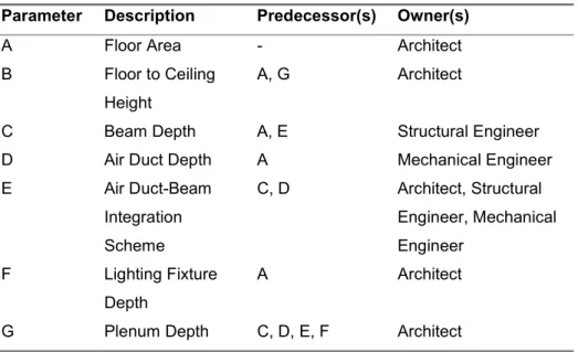
Table 4.4: List of Parameters, Their Predecessor(s) and Owner(s) for Suspended Ceiling Design... 56
Table 6.1: An Outline of the Design Process ... 123
LIST OF FIGURES
Figure 1.1: A Generalized Schema of Building Design Process ... 2
Figure 3.1: A Three-level Scheme for Process Modeling... 23
Figure 3.2: A View from GDCPP Process Map... 26
Figure 3.3: A Petri Net of an Activity that Uses Two Resources ... 30
Figure 3.4: An Example Data Flow Diagram showing Concept and Scheme Design Data Flows... 32
Figure 3.5: A Generic IDEF0 Diagram of an Activity... 34
Figure 3.6: A Part of a Process Model as an Entity-Relationship Diagram36 Figure 3.7: A Generic UML Activity Diagram ... 38
Figure 4.1: The Initial DSM of the Process ... 45
Figure 4.2: The Partitioned DSM ... 46
Figure 4.3: The Banded DSM ... 47
Figure 4.4: Tearing the DSM (a) Tear Decision (b) Torn DSM... 47
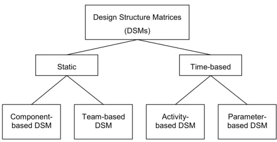
Figure 4.5: DSM Taxonomy... 49
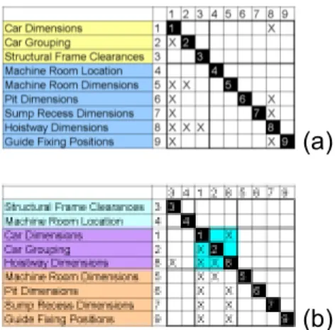
Figure 4.6: A Parameter-based DSM Example (a) The Initial Matrix (b) The Partitioned Matrix... 58
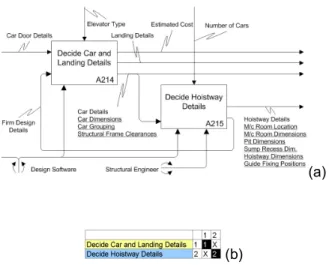
Figure 5.1: Two Coupled Activities of Elevator Design Process (a) IDEF0 Model (b) Activity-based DSM ... 82
Figure 5.2: Two Coupled Activities of Elevator Design Process (a) Initial Parameter-based DSM (b) Partitioned DSM... 83
Figure 5.4: An IFC Relationship Diagram of Elevator Car and its Frame.. 89
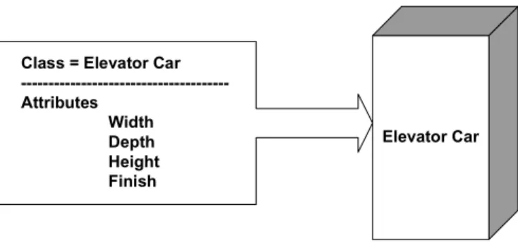
Figure 5.5: The Interfaces of Elevator Car Class in the IFC System... 90
Figure 5.6: Four different Views of Parameter-based Design ... 92
Figure 5.7: The Hierarchical Organization of IDEF0 Modeling... 95
Figure 5.8: The Four Domains of Suh’s Axiomatic Design Theory ... 97
Figure 5.9: Suh’s Domains Adapted to Building Design ... 98
Figure 5.10: Different Parameters of an Exterior Wall ... 99
Figure 5.11: The Proposed Implementation Model ... 106
Figure 5.12: A Workflow Proposal for a Project Management System Utilizing the Parameter-based DSM... 108
Figure 6.1: A System Design View of Suspended Ceiling ... 114
Figure 6.2: A Detail from A Suspended Ceiling System... 115
Figure 6.3: Layered (a) and Shared (b) Schemes for Integration of Structure, HVAC and Lighting Systems ... 118
Figure 6.4: Ground Floor Plan of Gürbulak Customs Building ... 122
Figure 6.5: The Scope of the Suspended Ceiling Design Model... 130
Figure 6.6: The Context Diagram of Suspended Ceiling Design... 131
Figure 6.7: An IDEF0 Model of Suspended Ceiling Lifecycle... 132
Figure 6.8: An IDEF0 Model of Suspended Ceiling Design ... 133
Figure 6.9: An IDEF0 Model of Suspended Ceiling System Interfaces... 134
Figure 6.10: An Example System Description Sheet ... 136
Figure 6.11: An Example Parameter Relations Sheet ... 136
Figure 6.12: Initial Parameter-based DSM of Suspended Ceiling Design at System Level ... 138
Figure 6.13: Initial Parameter-based DSM of Suspended Ceiling Design at
Assembly Level... 139
Figure 6.14: Partitioned Parameter-based DSM of Suspended Ceiling Design at System Level ... 140
Figure 6.15: Partitioned Parameter-based DSM of Suspended Ceiling Design at Assembly Level... 141
Figure 6.16: Banded Parameter-based DSM of Suspended Ceiling Design at System Level ... 142
Figure 6.17: Banded Parameter-based DSM of Suspended Ceiling Design at Assembly Level... 143
Figure 6.18: Three Configurations that Characterize a System ... 149
Figure 6.19: Information Flow Percentages in System Level DSM ... 150
Figure 6.20: Information Flow Percentages in Assembly Level DSM ... 151
Figure 7.1: System Details of Electric Traction (Left) and Hydraulic (Right) Elevators... 155
Figure 7.2: The Context Diagram of Elevator Design Process... 166
Figure 7.3: An IDEF0 Model of Elevator Life Cycle... 167
Figure 7.4: An IDEF0 Model of Elevator Design ... 168
Figure 7.5: An IDEF0 Model of Elevator Planning ... 169
Figure 7.6: An IDEF0 Model of Detailed Design of Elevators ... 170
Figure 7.7: Initial Parameter-based DSM of Elevator Design... 172
Figure 7.8: Partitioned Parameter-based DSM of Elevator Design... 173
1. INTRODUCTION
The Architecture/Engineering/Construction (AEC) industry is one of the multidisciplinary domains in which collaboration among related parties is of utmost importance. While the knowledge needed for building processes is distributed among the different participants from diverse disciplinary backgrounds, the product of their activities, i.e. the building itself, is (or should be) highly integrated. Thus, collaboration manifests itself as an important component of project success. In a survey of AEC companies in the U.S., collaboration among parties ranked first among the many factors that affect quality in design phase (Arditi and Günaydın, 1998).
This dissertation addresses the problem of collaboration from an
information flow perspective. The collaborative building design process is viewed as a series of interdependent decisions of different design
professionals and it is presupposed that like other processes, it is possible and useful to build quantifiable models of building design. In this
introductory chapter, the research problems and the objectives of the study are discussed and the structure of the dissertation is briefly outlined.
1.1 Problem Statement
The increasing complexity of buildings and a very competitive market place have been forcing design professionals to improve their processes in terms of time and quality. However, systematic design planning is not considered
in many building projects. This is due to the common misconception of some designers that design, being a creative process, cannot be planned effectively. Even when planning is done, it is performed in an intuitive manner based on discipline specific programs, despite the fact that effective design collaboration necessitates planning the flow of
interdisciplinary information. Relatively little research has been made on the management of the design process compared to production
management in construction (Formoso et al., 1998).
Figure 1.1: A Generalized Schema of Building Design Process(Adapted
from Kalay et al., 1998)
Figure 1.1 shows a generalized schema of current building design processes. As it can be observed in the figure, architects and design engineers (structural, mechanical, and electrical engineers) constitute the two foremost groups of building professionals. The main activity of
collaboration of architects and engineers in any project is evaluating and processing information and then communicating this information between various parties. Although there is an intense flow of information in building process, there is a lack of research to better understand and manipulate these flows (Eastman, 1999). Thus, in current practice, the
decision-making that led to specific configurations often remains invisible. These problems are probably due to the fact that building design is a very difficult process to manage. It involves thousands of decisions with numerous interdependencies in a highly uncertain environment. A large number of personnel are included and each group has its own terminology and design methods.
Process models of design aim to capture the complexities of the design process explained above. Such models are based on the premise that although designs may be unique in different projects, the process of
designing has an underlying structure which may not vary much across the projects. Although they are valuable in many aspects, existing process modeling methods in the AEC industry have considerable deficiencies. First of all, traditionally, building design has been planned by the same methods used to program construction. These techniques tend to view the design process as “document production” rather than flow of
interdisciplinary information. Secondly, existing methods represent design process at high levels and thus, they are not suitable for modeling multi-parameter problems. Finally, most of the existing models are not capable of representing and managing iterations which is a main characteristic of design.
With a view to alleviate these problems, this dissertation proposes
process modeling method for building design. Parameter-based DSM is a structured analysis technique originally developed in the product design field. The method aims to capture dependencies between decisions on design parameters and provides means to sequence those decisions according to the dependency structure. The method has been applied previously in the automotive industry (Black et al., 1990; Cesiel, 1993; Dong, 1999), robot design (Rask and Sunnersjö qtd. in Browning, 2001), aero-engine design (Mascoli, 1999), and software development (Browning, 1998). To the best of the author’s knowledge, however, this dissertation is the first study that has applied the method in building design.
In light of the discussion presented above, the research questions of this study are the following;
1. What is the information dependency pattern for design processes of architects and building design engineers?
2. Can the parameter-based design structure matrix method be utilized to analyze these processes? If so, how?
1.2 Thesis Objectives
The main goal of this dissertation is to propose an innovative process modeling method for building design process. Thus, this is a “methods” dissertation in which the desired methods are developed and/or
course of the study and they shaped the structure of the thesis presented in the next section.
1. Study the different approaches to collaboration research in order to develop a valid and well-grounded research strategy for analyzing collaborative building design processes.
2. Analyze the existing process modeling methods in the AEC industry and identify advantages and disadvantages of each model.
3. Propose a new process modeling method to alleviate the shortcomings of the existing methods.
4. Develop a framework for the application of the proposed method in building design and provide means for dealing with the specific needs of the application field.
5. Demonstrate the application of the proposed method via case studies.
6. Provide guidance for further studies on the topic.
1.3 Structure of the Thesis
Further chapters of the thesis are organized as follows:
Chapter 2 discusses the recently increased interest in collaborative design research in the AEC industry and its major drivers. Three different
educational approaches, studies of communication and negotiation, and the information modeling approach. Following a discussion of each approach, an explanation is included about why an information modeling approach is taken in this dissertation.
Chapter 3 analyzes existing process modeling methods in the AEC industry and identifies their common deficiencies. With a view to alleviate the problems in the currently available methods, a three-level scheme for AEC process modeling is proposed. In this scheme, parameter-based DSM represents the lowest level process modeling method, which enables bottom-up integration of the existing models.
Chapter 4 describes the design structure matrix method. Following an explanation of how the DSM method works, four types of DSMs (component-, team-, activity-, and parameter-based DSMs) and their applications are discussed. This chapter also reviews the available DSM tools.
Chapter 5 raises the issues related to the use of parameter-based DSM in building design. First, the paradigms underlying this type of research are uncovered. Then, expected benefits of the proposed method are discussed under three headings: process improvement, process integration, and other information processing applications. Finally, a knowledge
presented. The framework includes proposals on definition and
classification of parameters and means for dealing with large DSMs. At the end of the chapter, visions are presented for the utilization of the method along with software.
Chapters 6 and 7 present two case studies undertaken to demonstrate the application of the method in real life building design problems. Chapter 6 studies the suspended ceiling design process for a public building project in Turkey and Chapter 7 analyzes the elevator design process in general terms. These case studies were chosen to reflect different aspects of the framework proposed in Chapter 5. Besides the insights gained into the individual design processes, some common implications were also drawn from the case studies and discussed at the end of Chapter 7.
Chapter 8 concludes the findings of the thesis. Contributions of the study and challenges of the proposed method are discussed and suggestions are made for further research.
2. COLLABORATIVE DESIGN RESEARCH IN
THE CONSTRUCTION INDUSTRY
Researches on collaboration in the AEC industry have been based on a social paradigm of design defined by Mitchell (1994). According to this paradigm, design is the product of a team of professionals from different disciplines rather than a product of a single talented individual who has represented the image of designer since the Renaissance. The
paradigm prioritizes the “whole” over the “parts.” Mitchell presumes that designers, with the help of the ever developing communication and software technology, will come together in “virtual” design studios (or offices) to produce designs without geographical and time constraints (Mitchell, 1994). This vision has been realized to a great extent in the second half of the 1990’s when collaboration research gained a momentum.
Concurrent engineering is another paradigm that has driven
collaborative design research. The concept of concurrent engineering was initially proposed as a means to minimize product development time. Since then, many definitions of concurrent engineering have emerged in the literature. In general, it implies a systematic approach to the integrated and concurrent design of products and their related processes (Pena-Mora et al., 2000). Shared product knowledge and a communications architecture that will create a persistent space to
project are the basic notions of a concurrent engineering environment. Another important aim of concurrent engineering is to address important issues early in the project life-cycle. This necessitates involvement of all parties at a much earlier stage than would be the case in a traditional construction environment (Anumba and Duke, 2000).
Object-oriented programming and Internet technology are two emerging computing technologies that play a key role in enabling distributed and potentially concurrent collaboration for AEC projects. Object-oriented technology has been extensively used in software engineering and information management applications during the past decade. The basic idea of object-oriented programming is to combine software and data into the same object i.e. combination of the data describing the object and the operations related to it. It has enabled the definition of objects in a hierarchy so that an object can inherit the properties of its “parent” object. It is widely accepted that object-oriented programming suits the needs of building design, since it allows describing the
attributes and behavior of a broad range of building objects most of which are well described by their interfaces (Sanders, 1996).
Wide-area and local area computer networks have played an important role in more effective management of information in and across various AEC offices. Until the second half of the 1990s, the use of networking technologies was limited mainly to file transfer and electronic mail. After 1995, the World Wide Web (WWW) became widely available as a
graphical interface to the Internet based on a number of protocols for describing text, graphics, video, and sound data. Software used for browsing information on the WWW also became useful to view
company-specific information in a secured computing network. These developments gave way to software products for Internet-based viewing and sharing of project information (Zamanian and Pittman, 1999).
Today, collaborative design studies for the AEC industry include many different approaches and an increasing amount of basic and applied research. In the framework of this dissertation, the domain of
collaboration research is analyzed under three headings, namely,
educational approaches, studies of communication and negotiation, and information modeling.
2.1 Definitions of the General Terms
The Oxford English Dictionary defines the word “collaborate” as “to co-operate, especially in literary, artistic or scientific work.” The word is derived from the Latin words col labore which means to work along side one another. Collaboration can be thought of as joint problem solving. It stands for working with others toward shared goals. Compared to the similar word cooperation, collaboration implies more formal
relationships, stricter planning and division of roles and full commitment to a common mission (Kvan, 2000).
Schrage explains that a “shared space” is a prerequisite for any type of collaboration. A shared space is a medium where all participants can add their notations to the shared understanding that the participants are trying to create (Schrage quoted in Schulz, 1997). According to
empirical studies, shared understanding is an essential condition for team design (Valkenburg, 1998). The purpose of a shared space is not to create a presentation of some finished concept, but rather to allow the thoughts and works of participants to be understood by their partners during the process of creation (Schrage quoted in Schulz, 1997).
Communication, coordination, and negotiation are the other related terms. Communication involves the exchange of information, events and activities. Effective communication is a necessary, though not a sufficient condition to meaningful collaboration. Simply publishing information to a large group of participants does not mean that the recipients of that information are participating in the process.
Communication has often been a well-known bottleneck in large-scale complex projects. Costly breakdowns in communications occur regularly even in the traditional AEC projects of physically collocated teams (Qian and Gross, 1999). Coordination involves controlling the workflow and communication process and managing various interdependencies between activities and events. It allows efficient control mechanisms to coordinate group effort (Pena-Mora et al., 2000). Finally, negotiation means compromising when design changes proposed by some team
member are not agreed to by other members who find the implications of the proposed change not acceptable from their own design
perspectives (Peng, 1999).
2.2 Approaches to Collaboration Research
2.2.1 Educational Approaches
Professionalism is one of the major obstacles to effective collaboration between architects and building design engineers. Professionalism is not simply a collection of knowledge and practices, but also value systems of the professionals which guide their objectives and
processes. This type of socialization is largely due to the fragmented education of the design professionals. Newer educational approaches aim to address this fragmentation and to propose ways to overcome it. Some approaches claim that architects and engineers need to be educated together so they can learn how to work better together
(Wheeler, 1998). However, this solution seems to be impractical due to the huge and ever growing amount of knowledge in each profession. It is more reasonable to sensitize students to the issues, objectives, and concerns of the other discipline (Taşlı, 2001a). There are several attempts to implement interdisciplinary courses for architecture and engineering students and there is evidence that such courses provide students valuable insight of the value systems used by their peers (Jackson, 1997; Chinowsky and Robinson, 1995). Pultar (1999) claims that it might be useful to give a general design education to architecture
and structural engineering students for an initial period, after which, students should have the chance to choose their specialization field.
2.2.2 Studies of Communication and Negotiation
Developments in communication technologies have motivated a great amount of “technology-driven research” (Galle, 1995) in the field of computer supported collaborative work (CSCW) in the AEC industry. Internet-based technologies have formed the basis for collaboration of geographically distributed AEC teams which are often called “virtual offices.” (Low and Sloan, 2001). European Commission funded projects such as EVONET (European Virtual Office Network) and RECITE (Remote Electronic Construction Industry Telematics Experiment)
proved that electronic communications enable considerable increases in the operational efficiency of AEC firms (Moller, 1997).
Shared virtual reality environments utilizing VRML (Virtual Reality Modeling Language) models constitute another developing research field in computer supported communication in the AEC industry. These environments enable collaborating parties to be virtually located within a given three-dimensional environment in which they are able to interact with one another or with virtual objects that are also present in the environment. The intended aim of these environments is to create the illusion of “being there” (Caneparo, 2001; Woo et al., 2001; Lee et al., 2001; Atsuko et al., 2001).
There is also considerable interest in agent-based approaches for computer supported communication and negotiation in the AEC
industry. An agent embodies particular functionality and behaves in an autonomous manner. Agents conduct tasks such as gathering
information, communicating with one another as well as planning, scheduling and executing tasks. In a collaborative design context, individual agents may be responsible for either the design of subsystems, or for performing specific design tasks such as
performance analysis, cost analysis, and optimization (Veeramani et al., 1998; Pena-Mora et al., 2000).
Negotiation-based approaches to design collaboration often make use of constraint satisfaction techniques to approximate the space of
alternative solutions (Lottaz, 2000; Peng, 1999). Instead of negotiating over single values for parameters (which often creates artificial
conflicts), constraint satisfaction techniques offer the possibility to calculate, represent, and manipulate solution spaces. The specification of project requirements using mathematical expressions makes explicit information that may be invisible at first glance. In this way, conflicts can be detected easily and causal links can be deduced from the structure of the constraint satisfaction problem (Lottaz, 2000).
2.2.3 Information Modeling Approach
requirement of any project is evaluating and processing information and communicating that information between various parties. However, information related problems constitute the major cause of design failure (Baldwin et al., 1998). With a view to alleviate these problems, information modeling research has gained importance in recent years.
Following a discussion of information related problems in the AEC industry, this section introduces the information modeling approach as a means of alleviating these problems.
2.2.3.1 Information Related Problems in the Construction Industry The main information related problems in the construction industry are summarized below.
1. Separate models of the design for each discipline and multiple views of the same objects
This is probably the most acknowledged problem in the literature, which has motivated studies on modeling interdisciplinary information. It is recognized that architects and building design engineers model
buildings according to their particular points of views. Depending on the view taken, certain properties and descriptions of objects become
relevant. For example, a wall may be a space division element providing privacy in architectural context and it may be load bearing or
models are interdependent and they must coexist. Changes in one model inevitably affect the other one and vice versa.
2. Lack of integration between CAD tools
In the related literature, it is also well documented that there is a lack of integration between the current computer aided design (CAD) systems (Taşlı and Sagun, 2002; Stuurstraat and Tolman, 1999; Hew et al., 2001). Most of the practical and exploratory CAD tools focus on single discipline or a single task in the process. This situation is often referred in the related literature as an example of “islands of automation” in the AEC industry (Fruchter et al., 1996). Therefore, a considerable amount of research effort has been devoted to the development of systems capable of integrating a range of building design tools (Kalay et al., 1998).
3. Fragmentation of the construction industry
The AEC industry -unlike other large industries, such as the automotive, aerospace, and the electronics industries- is fragmented into numerous small organizations. Fragmentation in AEC is largely due to the growing complexity of building processes, which promotes increased
professional specialization. Specialization is also reinforced by
educational practices and socio-economic trends that reward excellence in ever-narrowing fields. As a result, while several related industries, such as automotive and shipbuilding manufacturing, have been
their operations, the construction industry continues to fail in this development. This is probably due to the fact that the larger
organizations in other industries have higher profits that enable them to invest larger sums of money in technology development. Furthermore, other industries have a few key organizations that can drive a
technology to suit their requirements (VTT, 2003).
4. “Document-based design” vs. “Model-based design”
Despite rapid developments in technology, the current construction project information paradigm is still primarily based on the use of traditional media such as drawings and faxes, and methods such as meetings. Consequently, all the participants in a specific project are required to convert paper-based information into electronic versions and vice-versa. This continual process of creating and translating
information according to the design and presentation medium used creates several bottlenecks in the flow of information. Many researchers believe that in order for the construction industry to meet this challenge, the development of an information modeling standard that enables sharing, storing and exchanging project information electronically is essential (Tolman, 1999). In the evolving model-based paradigm,
production of computable models of building objects and processes that are useful to those downstream in the process is a key aspect
5. Incomplete, uncertain, and untimely information
Any type of design is characterized by iteration. Incomplete, uncertain, or untimely information is likely to cause additional iterations which probably increase the duration and cost of the process. The problem of iteration is discussed at Chapter 5 in detail.
6. Lack of a shared understanding of objectives, values and processes
Shared understanding is a mutual view amongst the design participants on relevant design topics and design activities. Without this
understanding, decisions will not be supported by all team members and later activities in the design process can be restricted by different views of the team members (Valkenburg, 1998). Having a common understanding of information content of design entails shared models.
7. Invisible decision making
In conventional practices, the communications between design professionals is often at such a minimal level that the documents can only provide the most basic level of information. Even when the plans reflect the design process with absolute accuracy, the decision making that led up to specific configurations remain invisible. This is a
significant disadvantage when alternative solutions are searched in the process (Schulz, 1997).
the ever-changing status of the project in an attempt to eliminate design errors. However, in current processes of the AEC professionals,
communications are often informal and not documented. Thus, tracking and managing changes is a cumbersome task (Austin et al, 1994).
2.2.3.2 What is a Model?
A model can be defined as a representation of relevant characteristics of an artifact. In other words, it is a means of expressing certain
characteristics of an object, system or situation that exists, existed, or might exist (Echenique qtd. in Rowe, 1991). According to the Oxford English Dictionary, a model may be defined simply as “a representation of structure.” In the information modeling field, a model is used to represent the structure of information and how that information relates to other information.
Discussing models, it should always be borne in mind that no matter how much effort goes into its construction, a model can never be a perfect or complete representation of reality, because human beings do not have perfect information about the real world. Therefore, the
usefulness of models should be judged not against an imaginary perfection, but in comparison with the mental and descriptive models that could be used alternatively (Forrester qtd. in Radford and Gero, 1988).
2.2.3.3 Advantages of the Information Modeling Approach
The information modeling approach is taken in this dissertation, firstly because it is widely recognized that information modeling alleviates the problems presented in 2.2.3.1. It has already become a fundamental aspect of collaboration research. In fact, an information model underlies any type of computer supported collaborative work. Rezgui et al. (1996) explain that a great deal of work has already addressed collaborative design on the implementation side. However, a model-based solution has several advantages that go beyond particular implementations. Models are independent of any particular implementation and therefore they are more likely to survive the rapid evolution of information
technology. Furthermore, any model-based representation is potentially usable for other information-processing purposes.
2.2.3.4 Types of Information Models
Information models used in the AEC industry can be grouped as
product models and process models. A product model is an information model that implicitly contains data regarding form (geometry and
topology), function (requirements or intentions) and behavior
(performance) of a product and it is able to describe the product through its life cycle. In other words, such a model provides an abstract
description of facts, concepts, or instructions about a product. The role of the product model in this definition is equivalent to the role of the technical documentation in the current paper-based design and construction process (Tolman, 1999).
Since one of the most important requirements for a building product model is its capacity to allow different professionals to abstract different perspectives of the building from it (Dias, 1996), product modeling is a promising means to avoid iterations and misinterpretations from which traditional processes suffers. Moreover, it is widely accepted that a product model is a more complete and re-usable representation of a building for the whole building life cycle. Therefore, there have been many efforts to build a common product model for building design such as RATAS (Björk, 1994), COMBINE (Amor et al., 1995), COMMIT (Rezgui et al., 1996), CONCUR (Stuurstraat and Tolman, 1999), and ATLAS (Tolman, 1999).
A process model is a systematic representation of a process, which in a formal manner describes the aspects of the process that are relevant for the purpose and viewpoint of the process model (Karstila, 2000). The main purpose of process modeling is to gain knowledge of the existing process and to serve as a model for future implementation. There are three main uses of process models (Svensson et al., 1999):
1. Process Development and Improvement: A process model enables the capture of “as-is” information about a process. This model can then be analyzed and redeveloped as a “to-be” model that describes improvements. Some may argue that a detailed model of the
existing process is unnecessary and may take a long time to do. A simple model of the existing “as-is” process followed by a more detailed future “to-be” process should be enough. However, any
process development effort is highly unlikely to succeed without a comprehensive understanding of the existing state.
2. Information Technology (IT) Systems Development: Process models are used in IT development projects as a means for discovering and capturing the information content of a process and how that
information is to be exchanged between participants in the process. 3. Common Understanding of the Process: Process models are also an
important learning tool. A process model helps people visualize where they are in a process and what they need and must produce and when. In this way, it provides the basis for effective
collaboration.
Although the product modeling area has been well-established and related work is more or less complete, process modeling still presents a relatively less explored research domain (Eastman, 1999). In this
dissertation, the problem of collaboration in building design is studied from a process modeling perspective.
3. PROCESS MODELS OF DESIGN
The process modeling efforts in the AEC industry can be analyzed in three general groups, namely generic descriptive frameworks and formal activity models. This section identifies some shortcomings of the existing models and proposes the parameter-based DSM as the lowest level process modeling method (Figure 3.1). The analysis of the existing methods is presented in the following sections.
Figure 3.1: A Three-level Scheme for Process Modeling
3.1 Descriptive Generic Frameworks
3.1.1 Design Methods ModelsDescriptive methodological and philosophical frameworks of the design process originate from the 1960’s Design Methods movement. This movement claimed to bring systematic methods for designers in order to cope with the increased complexity of design process. Cross (1993) identifies two “generations” of design methods. 1960s “first generation” methods seemed simplistic and were not embraced by a large
audience. The second generation design methods, which started to
Modeling
Level Tools
Process Descriptive Generic Frameworks
Activity Formal Activity Models Parameter Parameter-based DSM
emerge at the early 1970s, moved away from the “omnipotence” of designers towards “satisficing” solutions and “argumentative” participatory process. These include Hubka (1982), Pahl and Beitz (1984), Cross (1989), and Pugh (1986) to name a few.
Design methods models defined design as a rational process composed of three basic steps: analysis, synthesis and evaluation. These steps were either formulated by linear flow charts, or by spiral forms
representing reiterating sequence. Another of their common
characteristics is that they represent the process at high levels with very little information at lower levels (Broadbent, 1988).
3.1.2 The RIBA Plan of Work
The RIBA Plan of Work (Phillips, 2001) is another generic framework which was originally published in 1963 as a standard method of operation for building construction, and is widely accepted as an operational model for the building industry in UK. The Plan of Work represents the whole building process from inception to feedback in terms of a logical sequence of work stages. According to the Plan of Work, a design project progresses from stages A to M in a linear fashion requiring the completion of one stage before proceeding to the next (Table 3.1). It is anticipated that the model will need only slight adjustments depending upon the size and complexity of the project.
Table 3.1: An Overview of the RIBA Plan of Work(Adapted from Nelson et. al., 1999) Pre-design A►B Design ►C►D►E Preparing to build ►F►G►H Construction ►J►K►L Post-Construction ►M Stage A: Inception Stage B: Feasibility
Stage C: Outline Proposals Stage D: Scheme Design Stage E: Detail Design Stage F: Production Info
Stage G: Bills of Quantities Stage H: Tender Action Stage J: Project Planning Stage K: Operations on Site Stage L: Completion
Stage M: Feedback
3.1.3 The Generic Design and Construction Process Protocol The Generic Design and Construction Process Protocol (GDCPP) developed at the University of Salford is a high level map defining the process in terms of activity zones. The zones contain high-level
processes spanning the duration of a project from inception to operation and maintenance. The process protocol also consists of deliverables in a form of documented project information such as stakeholder list, brief, etc. and logical dependencies between activities which are shown by interconnecting arrows.
The GDCCP breaks down the design and construction processes into eight activity zones namely, development, project, resource, design, production, facilities, health and safety, and process management, four broad stages –pre-project, pre-construction, construction, and post-construction–, and ten phases. The stage/gate approach to process management practiced in manufacturing industry was used to develop
the GDCPP. From the point of view of decision making during the process, there are so-called soft gates and hard gates. Soft gates imply that decisions may be approved conditionally afterwards. On the other hand, hard gates indicate final and firm decision points whether or not to proceed to the next phase of the process. This is because late design changes often cause substantial additional costs in construction
projects (Wu et al., 1998). All GDCPP process maps are publicized at a Web site hosted by the University of Salford (University of Salford, 2003).
Figure 3.2: A View from GDCPP Process Map (University of Salford, 2003)
Recently, the GDCPP ─in combination with Unified Modeling Language (UML) diagramming─ has constituted the base of process modeling approach proposed in EU ICCI cluster project IST-2001-33022 (Wix and Katranuschkov, 2002).
are merely used as generic guidelines rather than effective tools for process improvement and integration.
3.2 Formal Activity Models
Engineering design and product development is the forerunner of formal design process modeling. The process modeling methods used in software development have also been shown to be valuable for other design fields (Shi and Deng, 2000). Most engineering design process models are based on the observation that design is composed of a number of tasks that have an underlying structure. This focus on underlying structure implies that the models consider the most structured parts of the design process; this enables the use of
mathematical techniques. Unlike descriptive generic frameworks, formal activity level models are quantitative and graphical models that are capable of representing design processes in more detail.
This type of modeling includes network models such as the Project Evaluation and Review Technique (PERT), the Critical Path Method (CPM), Petri nets, Data flow diagrams, and the Integrated DEFinition Language 0 (IDEF0); information modeling methods such as the Entity Relationship Diagrams (ER) and Unified Modeling Language (UML); and Activity-based design structure matrix (DSM).
3.2.1 Network Models
Network models can overcome some of the drawbacks of generic models by exploiting activity relationships. Such models are based on the premise that once decomposed, the design process can be
described as an interconnected network of design tasks i.e. a directed graph. A directed graph (digraph) represents the precedence
relationships among tasks of a project. It consists of a set of nodes representing the design tasks and a set of directed lines connecting these nodes. The directed lines denote a dependency or a relationship between the connected tasks (Yassine et al., 1999). There are many variations of network models, but only the four basic types are
discussed below.
3.2.1.1 PERT/CPM
The Project Evaluation and Review Technique (PERT) and the Critical Path Method (CPM) are based on digraphs. The PERT method is the first example of time-based process modeling. In the PERT method, three probabilistic time estimates are given to each task, reflecting the uncertainty in the duration of tasks. The CPM is a variation of the PERT method. However, the time of any task can be compressed by allocating resources. Thus, CPM assumes a time-cost tradeoff rather than the probabilistic times used in PERT. CPM diagrams also graphically show the precedence interrelationships among product activities. It is possible
There are several limitations in this type of modeling such as the following (Shi and Deng, 2000):
1. They lack the ability to model feedback and iteration in the
projects, so that they cannot model projects as a dynamic decision process.
2. They deal with an activity as a non-stop process. However, in
practice activities may be interrupted when required conditions cannot be met.
3. They can be time-consuming to prepare, difficult to read and
to update.
Pultar (1990) has developed a progress-based scheduling technique based on progress charts and bar charts to overcome the problem of fragmentation of activities during the application of the conventional CPM to construction projects. CPM type of modeling has been used in many construction projects with varying degrees of success. However, the technique has remained to be useful for the construction phase of building process rather than the design phase.
3.2.1.2 Petri Nets
A more recent process model of design that describes information flows is a Petri net model. A Petri net is a graphical modeling tool that
consists of places, transitions, and arcs (Figure 3.3). Basically, it defines transitions that are interpreted as activities, and tokens that are
interpreted as resources. The idea is that resources (tokens) are used by activities (transitions), and then moved from one place to another. Input arcs connect places with transitions, while output arcs start at a transition and end at a place. A marking in a Petri net refers to a change in the state of the system. An initial state of a Petri net is called the initial marking. Transitions are only allowed to occur if they are enabled (all the preconditions for the activity are fulfilled). The concept of time can also be associated with a transition. Moreover, pre- and post- conditions can be added to a Petri net and additional attributes (colors) can be added to tokens (Karhu, 2001).
Figure 3.3 shows a process that consists of only one activity. To execute the activity, two resources have to be used. The net in Figure 3.3(a) models this process. Transition in t1 in Figure 3.3(b) is enabled because each of its input places, p1 and p2, contains a token. After the transition t1 occurs, p3 (the output place of t1) gets a token; the new marking is shown in Figure 3.3(c) (Zakarian and Kusiak, 2000).
Petri nets are promising for representing systems that are concurrent, asynchronous, distributed, and parallel. The disadvantages of Petri net descriptions include the lack of decomposition and hierarchy (Karhu, 2001), and emphasis on feasibility as the output measure of interest. Additionally, there is no weighting of the transitions; all transitions are implied to be of the same importance. Furthermore, the complete structure of the project must be done in advance if the model is
expected to have any useful predictive utility (Smith and Morrow, 1999).
Wakefield and Damrianant (1999) demonstrated how Petri nets, previously used for modeling computer networks and flexible
manufacturing systems, can be used for modeling construction systems and processes. They claim that the graphical nature of Petri Net models makes them relatively easy to understand, to build and to communicate to others. Furthermore, the graphical Petri Net representation is readily converted into algebraic representation that facilitates analysis and numerical simulation. In fact, Petri nets are aimed more at simulation rather than static process modeling.
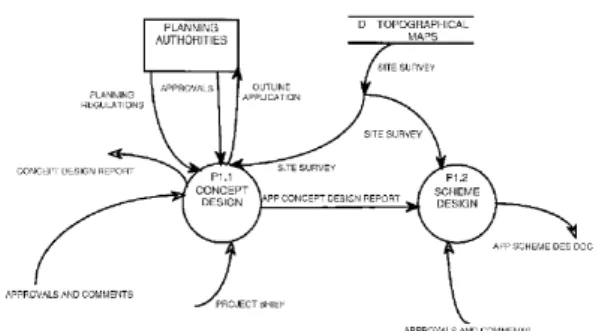
3.2.1.3 Data Flow Diagrams
Data flow diagramming emerged originally for software development (De Marco, 1979). A data flow diagram is constructed from four basic elements; namely, process, data or information flow, data store, and an external entity used as a source or sink of data flow. Baldwin et al.
(1999) applied these concepts to a building design process model and interpreted processes as individual design tasks, flows as design information flows, data stores as drawings etc., and external entities as clients, local authorities, etc. Abou-Zeid and Russell (qtd. in Karhu, 2001) also used data flow diagramming to study communications between participants of building design process.
Figure 3.4: An Example Data Flow Diagram showing Concept and Scheme Design Data Flows (Baldwin et al., 1999)
The method has the capability of presenting the models in a hierarchical form through decomposition. Data flow diagrams are not concerned with how processes are performed but view systems from an information point of view. They can also represent the iterations in processes, but do not provide any means to deal with them. Moreover, the performer of a process is not modeled with this method (Karhu, 2001).
3.2.1.4 IDEF0
Standard IDEF (U.S. Air Force, 1981) was developed from SADT (Structured Analysis and Design Technique) for process modeling in computer-integrated manufacturing and concurrent engineering. The IDEF model consists of hierarchically decomposed diagrams, along with text for each of the diagrams, and glossary of terms used in the
diagrams (Smith and Morrow, 1999).
The two basic components of the IDEF diagram are a box and arrows. Boxes represent processes, while the arrows represent different
interfaces such as input, output, control, and mechanism. Inputs are the data or objects that are transformed by process into output. Input
arrows are associated with the left side of an IDEF0 box. Outputs are the data or objects produced by a process. Output arrows are
associated with the right side of an IDEF0 box. Controls are conditions required to produce correct output. Data or objects modeled as controls may be transformed by the process, creating output. Control arrows are associated with the topside of an IDEF0 box. Mechanisms are the means used to conduct a process. Mechanism arrows are associated with the bottom side of an IDEF0 box. A generic IDEF diagram of a process is shown in Figure 3.5. In addition to the definition of the IDEF0 language, the IDEF0 methodology also prescribes procedures and techniques for developing and interpreting models, including ones for data gathering, diagram construction, review cycles and documentation (U.S. NIST, 1993).
Figure 3.5: A Generic IDEF0 Diagram of an Activity(U.S. NIST, 1993)
IDEF0 is probably the most widely used formal process modeling method in the AEC industry since it was declared as the preferred notation for the creation of graphical process models for Industry Foundation Classes (IFC) specification. Studies on IDEF0-based AEC process models include but are not limited to Sanvido and Norton (1994), Karhu (2000), and Rezgui et al. (2002).
As a modeling language, IDEF0 has the following advantages:
1. It is comprehensive and expressive, capable of graphically
representing a wide variety of operations to any level of detail.
2. It is a simple language, providing for rigorous and precise
expression, and promoting consistency of usage and interpretation.
3. It is well-tested and proven, through many years of use in Air
Force and other government development projects, and by private industry.
4. It can be generated by a variety of computer graphics tools;
numerous commercial products specifically support
Control
Input Output
However, like the other graph-based representations, IDEF0 also suffers from size limitations. It tends to grow rapidly for a large number of tasks and visual inspection of the information structure becomes very complex and misleading. Thus, it is more useful for high-level process representations rather than detailed processes. Moreover, process modeling techniques like SADT/IDEF0 are only well structured when the activities constitute the focus. Information, controls and mechanisms are connected to each process step but there is no way of analyzing the total information structure processed in the system. Although IDEF0 is capable of showing iterations in processes, it does not provide a means of resolving them (Svensson et al., 1999). Another limitation of the IDEF0 technique is that mainly document producing actions are captured. The technique gives weak support for modeling parallel sub-processes and for informal communication within a sub-process. Therefore, iterations between levels are difficult to analyze with IDEF0 (Malmström et al., 1999).
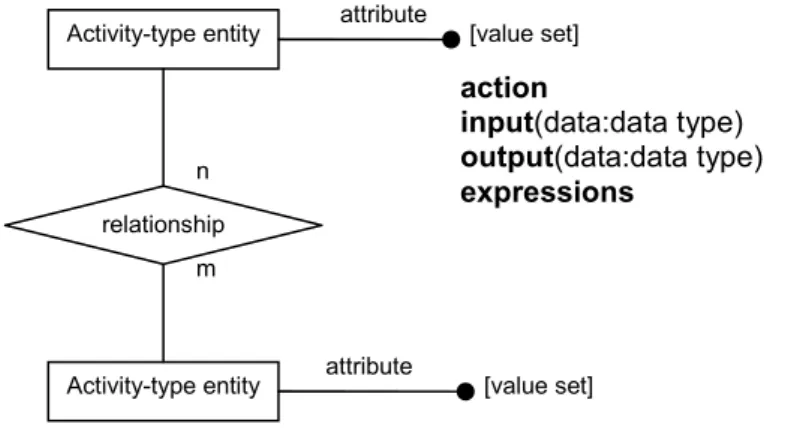
3.2.2 Entity-Relationship Diagrams
Information modeling methods like Entity-relationship (ER) diagrams and UML were originally developed for designing software intensive systems. ER diagrams were specifically developed to build relational databases. The method utilizes three major abstractions to describe the data; namely, entities, relationships, and attributes. The basic object that an ER model represents is an entity, which is a “thing” in the real
world with an independent existence. Each entity has particular
properties called attributes that describe it. A particular entity will have a value for each of its attributes. Whenever an attribute of one entity type refers to another entity type, some relationship exists. In the initial design of entity types, relationships are typically captured in the form of attributes. As the design is refined, these attributes are converted into relationships between entity types (Elmasri and Navathe, 1994).
Figure 3.6: A Part of a Process Model as an Entity-Relationship Diagram (Hong and Hong, 2001)
Hong and Hong (2001) have developed an entity-relationship based process model for structural design. They claim that entity-based approach to process modeling enables them to develop integrated and uniform product and process models. The ER diagramming was also used for building a relational database for GDCPP Map Creation tool by mapping the entities and relationships as database tables (Wu et al., 1998). attribute attribute [value set] [value set] Activity-type entity Activity-type entity n m relationship action input(data:data type) output(data:data type) expressions
Entity-relationship diagrams are beneficial for producing integrated product and process models, however, the method is more desirable for top-down design process, since it allows high level abstraction in
representing design information and design activities (Hong and Hong, 2001). Svensson et al. (1999) explain that if the process modeled is a repetitive task, ER modeling can be useful, since only the type of
information is relevant, regardless of what types of parts the documents are describing.
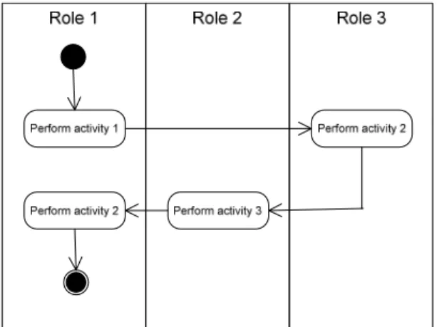
3.2.3 Unified Modeling Language
Unified Modeling Language (UML) is a standard modeling language for software development. It is a sophisticated language involving many types of diagrams; two of which are especially relevant for process modeling purposes. UML activity diagrams enable identification of communication between activities undertaken by different roles within a process. Activity diagrams address the dynamic view of a system. Use case diagrams show a set of use cases and actors and their
relationships. Such diagrams address the static use case view of a system (Booch et. al., 1998). Use case diagrams of UML were recently used in OSMOS (a European Union research project) to capture the sequence of actions performed by actors in virtual construction enterprises (Rezgui et al., 2002).
Figure 3.7: A Generic UML Activity Diagram (Booch et al., 1998)
The limitations of modeling processes with UML are as follows. First, UML is not suitable for process modeling if the purpose is to study the current state of the processes. Moreover, UML does not include any suitable technique for mid-level process modeling such as IDEF0. Therefore, it is hard to get an overview of the modeled system.
Information modeling tools like ER diagrams and UML are capable of representing dependency relationships, but they do not provide a means for analyzing the cycles in a process. Thus, their functionality as a process modeling method lies largely in IT system development rather than process integration and improvement.
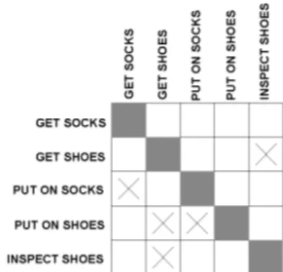
3.2.4 Activity-based DSM
Activity-based DSM is a method capable of identifying and resolving iterations in a process. The details of the method and applications are discussed in the next chapter. However, a brief analysis of its
advantages and disadvantages are presented below to support the conclusions made in 3.4.
The effectiveness of the activity-based DSM in sequencing activities has been shown in previous research (Austin et al., 2000); however, like the other methods reviewed in this chapter, it is too abstract to define, in detail, for complex multi-parameter problems. Furthermore, it has
another considerable shortcoming; activities can be described on multiple hierarchical levels, but in an activity-based DSM, it is difficult to see at which hierarchical level each activity is described. In fact, a precise definition of activities is lacking in DSM literature. Therefore, there always seems to be a possibility of comparing activities at
different levels as if they were at the same level. This problem is solved by the theoretical assumption that all activities are described at the lowest hierarchical level. However, when decomposition ends at an activity level, this assumption cannot be fully supported. At the lowest level, the design activities should be decomposed into parameter decision points.
3.3 Conventional/Empirical Methods
In the construction industry, chart-based scheduling is still the most widely used process modeling method. The milestone chart method consists of identifying the target completion date for each activity in the task outline. Bar charts (also known as Gantt charts) consist of a list of tasks along the left side of a page with horizontal bars along the right
side indicating the scheduled start and finish dates for each task. Charts are easy to prepare and use, but their best applications are limited to short design projects with few participants and little interrelationship between activities since, they are incapable of representing the interrelationships.
3.4 Shortcomings of Current Building Design
Process Models
Having analyzed the most widely used process modeling methods in the AEC industry, the following deficiencies are observed:
1. The complexity of design processes entails detailed analyses to gain insight into process structures. However, current process models used in the industry have a top-down approach including very little information about interrelationships at lower levels. Of course, one of the reasons why many process models fail to represent the detailed process is because of the intricacy it adds. Graphical models
become so tangled as the process is represented at lower levels that the descriptiveness of the tools diminishes. The DSM method works well in such situations, since it is a compact, visual and analytically advantageous format for complex systems.
The developments in the computer technology also support building and manipulating detailed models. When standardization efforts
have been refined and detailed (Tolman, 1999). Thus, it can be expected that building design process modeling would follow the same path toward comprehensive and low-level models.
2. Building design is characterized by iteration (rework). However, many process models can not represent iterative processes; even the models that are capable of identifying iterations can not resolve them (except the DSM method). In fact, systematic means for dealing with iterations are not established in the construction industry. Concurrent work is often seen as a way to reduce cycle time but, if concurrent activities are chosen arbitrarily without considering their dependencies, this can lead to abundant iteration and increased cycle time.
Thus, it can be clearly stated that there is a need for a low-level analysis tool that is capable of identifying and resolving iterations in AEC
process models. As a solution to the shortcomings of the existing methods discussed in the previous section, this dissertation proposes the parameter-based DSM as the lowest level process modeling method, which enables bottom-up integration of existing process- and activity-level models.