A Parametric Analysis of Finite Phased Arrays of Printed
Dipoles on Large Circular Cylinders and Comparisons with the
Planar Case
B. Giiner, V. B. ErfCrk'and 0. Bakw
Elecrricol& Electronics Eng. Depr. Bilken1 Univ.. TR-06800 Ankara, Turkqy. E-mail: voh@@ee,bil!eoredu.fr. Tel: ++90 312 2903154
INTRODUCTION
Although the primary concem in the design of antennas is to be able to send and receive information in a fast and accurate way, there are other i m p o m t practical constraints to be met. Many military and commercial applications require the use of antennas that conform to the main body. For example, when an antenna is mounted on the surface of a ship, aeroplane or a missile, conformality to the surface is generally aimed due to the reasom like aerodynamic constraints. reduced radm cross section
(RCS),
space limitations or aesthetic concems. However, the design and analysis tools availablefar
the conformal arrays d o not provide enough efficiency and accuracy to be practically useful, especially for electrically large, cylindrically shaped coated host bodies.Recently, a hybrid MoWGreen's function technique in the spatial domain is developed, which improves the efficiency and accuracy problems in the analysis of eonformal arrays [I],
[Z].
In this paper, this technique is used to perform B full-wave analysis of large phnscd arrays of printed dipoles an electrically large material coated circular cylinders of both axially and circumferentially oriented dipoles. The effects of several m a y and supporting smchlre parameters are obselvcd. Results are also compared with the corresponding planar arrays. Consequently, a complete understandingon
the performance of a m y s of printed dipolesan
large coated cylinders with respect to several a m y parameters (i.e. the dielectric consmt, thiclmesr of the coating material. the direction of +he dipoles) as well as the effects of eurvame (compared to planar mays) are investigated.FORMULATION
The geometry consirll of finite, periodic arrays of (ZN+l)r(2M+I) identical r-directed and @-directed printed dipoles. The dipoles are mounted
on
the air-dielectric interface ofan
infinitely long, cylindrically shaped grounded dielectric mbStrate with an inner radius a, outer radius d, ihiclmcss th = d - U and relative permittivity E, > I . Funhemare, the dipoles are assumed to be center-fed with an ideal delta gap generator, and each dipole has a generator terminating impedanceG.
The hybrid MoWGreen's function solution for this problem follows the following procedure:By forming an electrical field integral equation (EFIE) such that the total electrical field in the direction o f t h e orientation of the dipole must vanish on the dipole surfaces, and wing Galerkin's MOM solution, the following matrix equation is obtained [3]:
( [ Z ] + [ Z T ] ) . I =
v .
(1)In (I),
V
is the voltage vector which is related to the excitation of the dipoles. Using a singleexpansion mode for each dipole, the voltage vector element for the pq'I dipole becomes
(2) -jX, sin8,dror((i -PA() -jkocor8,qd,
v,-e
where
(ei,+,)
being the scan direction of the beam. I = [Im] is the utknown Yeclor of expansion coefficients (current vector) whose values are going to be found viaM O M
procedure, [Z,] is the diagonal generator terminating impedance matrix, and finally [Z] is the impedance matrix of the array elements whose entries are given byzm,,
= [Idsr I I d s l fw(rm)%(rM/i)fnm(i).
(3)c
..sIn (3) r, and rim are the position V ~ C ~ O I S of the pq" and nm" dipoles, G,(rw /rmL) is the appropriate dyadic Green's function component and fnm(rmL) and fw
(r,)
arc the,piece-wise sinusoidal basis and testing functions, respectively.As the anay size becomes larger, the impanance of the fast and accurate calcula&m of the impedance matrix increases. This is achieved via efficient and accurate ~alculation of the Green's function G u . ( g
/cl-)
component for arbitrary source and observation locations. Therefore,three diffrrenr ~pairal domain representations are used to Bod the Green's function in the most efficient and accurate way, a l l afwhich are valid in different but overlapping regions ofapace.
The first one i s a steepest desccnt path (SDP) representation [4], which is valid at the qff-paraxial region. This representation is based on the efficient numerical evaluation of a circumferentially propagating series representation ofthe appropriate Green's function along the SDP on which the integrand decays mast rapidly. The second representation is he paraxial spatial domain representation [ 5 ] , which is valid along the paraxial region. In this representation, we approximnte the Green's function by a Fourier Series (FS) using the periodicity of the circumferentially propagating series representation of the appropriate Green's function in one of its variables. The coefficients of rhe FS expansion can be found by a simple numerical integration algorithm. The algodhm used determines the accuracy and efficiency of this method. Including only the two leading terms of the FS expansion gives enough accuracy for most cases. Bath SDP and
FS
representations Iooscs their accuracy whcn the Separation between the source and observation points is $mall. Since this work is focusing an elccmcally large cylinders, for small sy~rations cylinder surface can be considered locally flat161.
Hence, planar appmximations are used for Eelf~tenn e"a1UafionS.Several performance metric5 [ 3 ] . [7] for both axially and circumferentially oriented finite printed dipoles on coated cylinders, the effects of a m y and host body parameters on their behavior, as well as the effects of he cuwahlre and array clement orientation are investigated afler solving the matrix equation given by (I).
NUMERICAL RESULTS
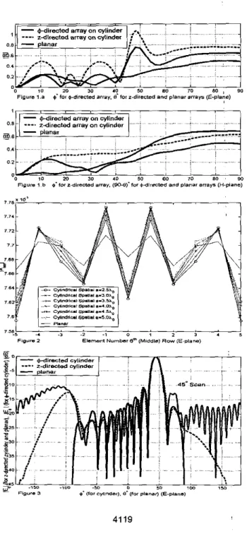
Figure I .a and Figure I .b illustrale the magnitude ofthe reflection coefficient v e n u scan angle of 111. I I 0- and :-directed dipole arrays on a dielectric coated circular cylinder with a = 3%. 4 =
@.@6&, e:, = 3.25 as well as the same result for a planar array along the E- and H- planes, respectively. The dipole dimensions are (0.39ho. 0.01&) for the length and width of each dipole, respectively and the dipoles are uniformly spaced from their neighbors by distances of 0.54 in I- and C- direcrions (x- and y- for planar case), respectively. It is seen that the array p i axially oriented dipoles on rhc cylinder shows B scan blindness along the E-plane (the magnitude ofthe reflection coefficient exceeds wily) at approximately 4 8 O . However, the scan blindness
phenomenon is observed for neither the array of circumferentially oriented dipoles on the cylinder nor the planar array. Along the H-plane, none of the arrays shows B scan blindness. Sincc scan blindness is relaled with the surface wave fields excited within the wbsuate, the curyaNre effects
as well as the orientation of the a m y element$ will change the behavior afthese fields. In Figure 2, the change in the magnitudes of the current^ on the dipoles for the middle row (€-plane) of a 11x1 I @-directed array is shown when (1 is varied between 2.54 and 5 4 , and they are compared with the corrsrponding planar array with all other parameten being the same as above. Although the c~rrents of the dipoles are close to each other far cylindrical arrays with different inner radii, it can still be seen that as the cylinder radius increases the current levels become closer to the planar array results whish is the limiting case of the cylindrical m y when
Le
radius goes to infinity.Figure 3 shows the normalized E-plane far-field patkm of l l x l l 6- and 1-dirceted dipole arrays on a dislscnic coated circular cylinder, and an 11x1 I planar array for a 45'scan angle with the same parameters used as in Figures 1.a and 1.b. It i s seen that although the pattem for the
cylindrical and planar cases
are
clme far the main lobe, away from the main lobe a significant difference OEEUTS due to the curvaNre of the cylinder. The sidelobe level^ for the cylindrical m y s are higher since some af the element paltems have their peaks other than the intended main beam direetion Since no special beamforming technique is used.CONCLUSIONS
A parametric sNdy of finite phased arrays of printed dipoles
an
eleehically large coated cylinders is performed using s spatial domain hybrid MoMlGicen's function technique. Dipoles' currents and several performance metries like active reflection coefficient and input impedances of the dipoles are calculated and compared with their planar counterpam. The effects of the curyaNre, dipole orientation and ehangss in the array and host body parameter^ are abservsd and discussed. Several more numerical examples will be presented during the presentation.REFERENCES
[I] V.
B.
EINrk, R. G. Rojas and K. W. Lce, "Analysis of finite arrays of axially directed pnnted dipoles on electrically large circular cylinders", accepted to IEEE Twm. Anlennos ondPmpagor. [21 B. Gilner and V. B. EINrk, "Analysis of finite arrays of circumferentially oriented printed dipales on electrically large cylinders", 2003 IEEE AP-S Inl. Symp. And USNC/CNCA,RSI Nalional Radio Science M ~ i n p , Columbus, OH, June 22-27 2003.[31 D. M. Pozar, "Analysis of finite phased arrays of printed dipoles", IEEE Trans. Anrennm and Propogal., v01.33,no.lO,pp. 1045-1053,Oct. 1985.
[4] V.
B.
ErNrk and R. G. Rojas, "Efficient computation of surface fields excited on a dielectric coated circular cylinder", IEEE Tram. Anlennm ondPrapugor., ~01.48, pp. 1507.1516, Oct. 2000. [SI V.B.
Ertllrk and R. G. Rojas, "Paraxial space-domain formulation far surface fields on dielectric coated circular cylinder", IEEE Trons. Anlennm and Propagot., vol.50, pp. 1577-1587. Nov. 2002.[6] S. Barkeshli,
P.
H. Pathak and M. Marin, "An asymptotic closed-form microsnip surface Green's function for the cfflcicnt moment method analysis of muNal coupling in microstripantennas", IEEE Tram. Anlennm and Propogof., ~01.38, pp. 1374.1383, Sept. 1990.
[7]
R.
C. Hanren, Phmed A r r q Anlennas. New York, John Wiley & Sons Inc., 1998.[SI J. Ash!eenaq. S . Shtrikman and D. Treves, "Electric surface current model for the analysis of microship a n t c m on cylindrical bodies", IEEE Trans. A d e n n m and Propogoi., ~01.33, pp. 295-300, March 1985.
00 10 m 30 40. 50 60 10 BO
,
90Figure 7.a i t o r O-diieNd @may. B tor z - d i r e a d and p l a n a r s r n ~ (€-plancl
. . ~ . ,..