103 Volume 4, No 1 | Summer 2020, 103-111
ARAŞTIRMA MAKALESİ / RESEARCH ARTICLE
AUTOMATIC COMBINATION OF USER VIEWS FOR DATABASE CREATION
Sefer KURNAZ1
1Altınbaş University, Faculty of Engineering and Natural Sciences, Department of Computer
Engineering, Istanbul
[email protected], ORCID: 0000-0002-7666-2639 Erden BAŞAR2
2International Final University 1Altinbas University, Istanbul
[email protected], ORCID: 0000-0001-7134-6971
GELİŞ TARİHİ/RECEIVED DATE: 01.06.2020 KABUL TARİHİ/ACCEPTED DATE: 02.06.2020 Abstract
People make up their minds in accordance with the information that they have in hand. If they have the right information the decision will be right otherwise it will be inaccurate. Information can be created on demand, which means when information is needed it should be created as soon as possible. We can ask ourselves “What is the information?” If it is going to help me make my mind, I have to define it. Information can be defined as processed data. Data itself means raw information, while information is the form of meaningful data. In this study we are presenting how to build our data base to save information in correct form to create useful information. (Kurnaz and Başar, 1991)
Keyword: Database, Information, Data
VERİTABANI OLUŞTURMADA, KULLANICI GÖRÜŞLERİNİN BİLGİSAYAR PROGRAM İLE OTOMATİK BÜTÜNLEŞTİRİLMESİ Özet
İnsanlar kararlarını ellerinde bulunan bilgiye göre verirler. Eğer eldeki bilgi doğru ise verilen karar da doğru olur, değilse karar yanlış olur. Bilgi ihtiyaç duyulduğu anda elde edilmelidir. Bunun anlamı bilgi ihtiyaç duyulduğunda hemen üretilmelidir. O zaman kendi kendimize bilgi nedir? sorusunu sorabiliriz. Eğer karar vermeme yardım edecekse bilgiyi tanımlayabilmeliyim. Bilgi işlenmiş veri olarak tanımlanabilir. Veri ise işlenmemiş bilgi olarak tanımlanabilir. Detaylı açıklama takip eden paragraflarda verilmektedir. Bu çalışmada biz veritabanımızı nasıl oluşturalımki veriyi doğru formatta saklasın ve ihtiyaç duyduğumuzda istediğimiz bilgiyi bize doğru olarak üretebilsin.
104
1. INTRODUCTION
We can save our data in different ways and in different formats, such as in files and in databases. We are not going to explain file system here, although they are used in database management system. There are different types of database management systems that can be used by the users to process their data. One of them is relational database management system. In relational database management system all entities are shown as tables. We can define a table as an entity set. A student table can be given as an example that composed of “Number”, “Name,” and “Address”. This does not mean this table is ready to be part of the database and is ready to be used by the users. We have to apply some process on tables before creating them in database. Before explaining these process lets make some general definitions. (Kurnaz and Başar, 1991)
a. Entity: It is an object that can be separable at least one feature from the other objects. As an example; a student is different from an instructor. Instructor teaches and student is a learner who learns what has been taught.
b. Attribute: It is a field of an entity. Number is an attribute of student. c. Key: is the unique attribute value in the database.
d. Cardinality: The numbers of rows or records in a table. e. Degree: The number of attributes in a table.
The records that composed of the entities data are saved in files on hard disk. As an example we can save student records in file called “Student” and the course records can be composed in a file called “Course”. When information is requested, an SQL command dealing with that information is written and executed in the database.
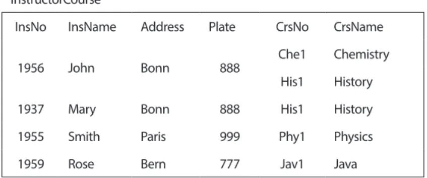
In order to create correct information, tables in database must satisfy canonical form conditions. Before creating a database each table should be tested in accordance with normal form rules. Table called “Instructor Course” as shown in Fig.1 is going to be used while we are explaining normal form rules. Now we can start to define normal forms and explain what we are talking about.
It will be good to explain table “Instructor Course” column names, before starting. Instructor Course: The name of Instructor Course Table,
InsNo: Instructor Number, InsName: Instructor Name, Address: Address,
Plate: Plate number of Address, CrsNo: Course Number, CrsName: Course Name.
105
InstructorCourse
InsNo InsName Address Plate CrsNo CrsName
1956 John Bonn 888 Che1 Chemistry
His1 History
1937 Mary Bonn 888 His1 History
1955 Smith Paris 999 Phy1 Physics
1959 Rose Bern 777 Jav1 Java
Fig.1 General Table 2. NORMAL FORMS
2.1. First Normal Form (1NF)
1NF: A relation R is in the first normal form if and only if all underlying simple domains contain atomic values only. (Date, 1990)
The table presented in Fig.1 doesn’t contain this rule. First record is different than the others. Its all fields are not atomic. This table must be modified and all cells must have atomic data, otherwise it can not be created in database. The updated structure of Fig.1 is shown in Fig. 2.
InstructorCourse
InsNo InsName Address Plate CrsNo CrsName
1956 John Bonn 888 Che1 Chemistry
1956 John Bonn 888 His1 History
1937 Mary Bonn 888 His1 History
1955 Smith Paris 999 Phy1 Physic
1959 Rose Bern 777 Jav1 Java
Fig.2 A able is in 1NF
Table in Fig. 2 is in 1NF. Each cell has atomic element. In another words each field has an atomic value. The record “InsNo=1956” is doubled. We have solved 1NF problem but now we have another problem. Although in Fig. 2 1NF cannot be created in database.
To satisfy 1NF requirements are not enough to be created in database. In order to create database each table must satisfy “Insert”, “Delete” and “Update” anomaly tests rules. Let’s apply these anomaly rules in Fig.2 a. Insert Anomaly Test.
106
Suppose we want to hire a new Instructor “1980, Sue, London, 555”, but we want to assign course to her at the beginning of the semester. Since primary key is composed of InsNo and CrsNo, we can not write her record to table. We have insert anomaly. Let’s look from course side. If we want to open a new course and if we don’t have anybody that teaches this course, we can not write course data to database. The primary key or its parts can not be null.
b. Delete Anomaly Test.
Suppose we want to delete record (1955, Smith, Paris, 999) from database. This record can not be deleted by itself. Record (phy1, Physics) will be deleted with it. This is not normal. If we delete record, we will loose the data dealing with physics course. This is deletion anomaly. In real life when an instructor fired, the course information does not change.
Let’s look from course side. Suppose the record “Jav1, Java” is requested to be delete from the table. At that time record “1959, Rose, Bern, 777” is going to be deleted from the table also. We just wanted to delete “Jav1, Java” record from database. We didn’t want to delete instructor’s record. This is a deletion anomaly. This anomaly should be prevented.
c. Update Anomaly Test.
Suppose record “1956, John, Bonn, 888” owner of “John” moved from “Bonn” to “Bern”. At that time, we are going to update more than one record. This is an “Update Anomaly”. As presented in Fig.2 where we have “Insert, Delete and Update Anomaly” conditions. That means this table is not suitable to create in database. We have to modify it and have it obey the normalization rules. 1NF rules is not enough for a table that can be created in database. Let’s define second normal form and apply its rules.
2.2. Second Normal Form (2NF)
Second Normal Form (2NF): A relation R is said to be in 2NF if and only if it is 1NF and the nonkey attributes are fully functionally dependent on the primary key. (Date, 1990)
Let’s apply this rule to the table in Fig.2. In order to do this, we first draw the functional dependency figure as seen in Fig.1 of this table.
Let’s look from course side. If we want to open a new course and if we don’t have
anybody that teaches this course, we can not write course data to database. The
primary key or its parts can not be null.
b. Delete Anomaly Test.
Suppose we want to delete record (1955, Smith, Paris, 999) from database. This
record can not be deleted by itself. Record (phy1, Physics) will be deleted with it.
This is not normal. If we delete record, we will loose the data dealing with physics
course. This is deletion anomaly. In real life when an instructor fired, the course
information does not change.
Let’s look from course side. Suppose the record “Jav1, Java” is requested to be delete
from the table. At that time record “1959, Rose, Bern, 777” is going to be deleted
from the table also. We just wanted to delete “Jav1, Java” record from database. We
didn’t want to delete instructor’s record. This is a deletion anomaly. This anomaly
should be prevented.
c. Update Anomaly Test.
Suppose record “1956, John, Bonn, 888” owner of “John” moved from “Bonn” to
“Bern”. At that time, we are going to update more than one record. This is an “Update
Anomaly”. As presented in Fig.2 where we have “Insert, Delete and Update
Anomaly” conditions. That means this table is not suitable to create in database. We
have to modify it and have it obey the normalization rules. 1NF rules is not enough
for a table that can be created in database. Let’s define second normal form and apply
its rules.
2.2. Second Normal Form (2NF)
Second Normal Form (2NF): A relation R is said to be in 2NF if and only if it is 1NF
and the nonkey attributes are fully functionally dependent on the primary key. (Date,
1990)
Let’s apply this rule to the table in Fig.2. In order to do this, we first draw the
functional dependency figure as seen in Fig.1 of this table.
InsNo
InsName
Address
Plate
CrsName
CrsNo
Fig.3 Functional drawing of table in Fig.2(Martin, J. 1977)
Functional dependency diagram uses bubbles and arrows to show functional
dependencies. As you see in Fig.3 each attribute is located in a single bubble. Only
combined primary key is located in a single bubble InsNo its components. The arrow
lines are drawn from primary key group to other attributes.
107
Functional dependency diagram uses bubbles and arrows to show functional dependencies. As you see in Fig.3 each attribute is located in a single bubble. Only combined primary key is located in a single bubble InsNo its components. The arrow lines are drawn from primary key group to other attributes. Primary key or primary key group must functionally determine nonkey attributes. Another way of saying, nonkey attributes must be functionally dependent on primary key or primary key group.
Primary key or primary key group must functionally determine nonkey attributes.
Another way of saying, nonkey attributes must be functionally dependent on primary
key or primary key group.
InsNo
InsName
Address
Plate
CrsName
CrsNo
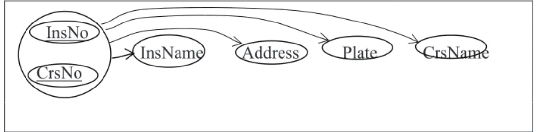
Fig.4 Unsuitable functional dependencies(Martin, J. 1977)
In our example as shown in Fig.4, primary key is composed of two attributes. Each
nonkey attribute must be functional dependent to this primary key group or this
primary key must functionally determine these non key attributes.
When we look at Fig.4, we can see that there is no fully functional dependency
between primary key and “InsName”. To reach “InsName” we don’t need all primary
key. “InsNo”, part of primary key, is enough to reach it. It means “InsName” is
partially depend on primary key
We can see the same situation between “CrsNo” and “CrsName”. We don’t need
primary key to reach “CrsName”. “CrsNo” is enough to reach “CrsName”. It means
that “CrsName” is partially dependent to primary key. “CrsName” is not fully
functionally dependent to primary key.
Now we have to modify Fig.4 and make it suitable to 2NF rules. In order to do this,
we have to define two different entities. Fig.4 is composed of two different entities.
These are: “Instructor (Ins)” and “Course (Crs)”. Let’s divide this figure in two sub
figures.
InsNo InsName Address
Plate
CrsNo
CrsName
(a.Ins)
(b.Crs)
Fig.5 functional dependencies of “Ins” and “Crs” tables(Martin, J. 1977)
In Fig.5 we have two different functional dependency diagrams. One of them is for
Instructor (Ins) and the other is for Course (Crs). “Crs” diagram satisfy the
requirements of 2NF. Depending on these two diagrams we can recreate table in Fig.2
as presented in Fig.6. Fig.6 is the recreated form of Fig.2. As you see Fig.6 will be
revaluate for functionally relationships. In fig.6 “Ins” is the abbreviate form of
instructor, Crs is the abbreviate form of courses.
Ins
Crs
InsNo InsName Address Plate
CrsNo CrsName
1956
John
Bonn
888
Che1
Chemistry
1937
Mary
Bonn
888
His1
History
Fig.4 Unsuitable functional dependencies(Martin, J. 1977)
In our example as shown in Fig.4, primary key is composed of two attributes. Each nonkey attribute must be functional dependent to this primary key group or this primary key must functionally determine these non key attributes.
When we look at Fig.4, we can see that there is no fully functional dependency between primary key and “InsName”. To reach “InsName” we don’t need all primary key. “InsNo”, part of primary key, is enough to reach it. It means “InsName” is partially depend on primary key
We can see the same situation between “CrsNo” and “CrsName”. We don’t need primary key to reach “CrsName”. “CrsNo” is enough to reach “CrsName”. It means that “CrsName” is partially dependent to primary key. “CrsName” is not fully functionally dependent to primary key.
Now we have to modify Fig.4 and make it suitable to 2NF rules. In order to do this, we have to define two different entities. Fig.4 is composed of two different entities. These are: “Instructor (Ins)” and “Course (Crs)”. Let’s divide this figure in two sub figures.
Primary key or primary key group must functionally determine nonkey attributes.
Another way of saying, nonkey attributes must be functionally dependent on primary
key or primary key group.
InsNo
InsName
Address
Plate
CrsName
CrsNo
Fig.4 Unsuitable functional dependencies(Martin, J. 1977)
In our example as shown in Fig.4, primary key is composed of two attributes. Each
nonkey attribute must be functional dependent to this primary key group or this
primary key must functionally determine these non key attributes.
When we look at Fig.4, we can see that there is no fully functional dependency
between primary key and “InsName”. To reach “InsName” we don’t need all primary
key. “InsNo”, part of primary key, is enough to reach it. It means “InsName” is
partially depend on primary key
We can see the same situation between “CrsNo” and “CrsName”. We don’t need
primary key to reach “CrsName”. “CrsNo” is enough to reach “CrsName”. It means
that “CrsName” is partially dependent to primary key. “CrsName” is not fully
functionally dependent to primary key.
Now we have to modify Fig.4 and make it suitable to 2NF rules. In order to do this,
we have to define two different entities. Fig.4 is composed of two different entities.
These are: “Instructor (Ins)” and “Course (Crs)”. Let’s divide this figure in two sub
figures.
InsNo InsName Address
Plate
CrsNo
CrsName
(a.Ins)
(b.Crs)
Fig.5 functional dependencies of “Ins” and “Crs” tables(Martin, J. 1977)
In Fig.5 we have two different functional dependency diagrams. One of them is for
Instructor (Ins) and the other is for Course (Crs). “Crs” diagram satisfy the
requirements of 2NF. Depending on these two diagrams we can recreate table in Fig.2
as presented in Fig.6. Fig.6 is the recreated form of Fig.2. As you see Fig.6 will be
revaluate for functionally relationships. In fig.6 “Ins” is the abbreviate form of
instructor, Crs is the abbreviate form of courses.
Ins
Crs
InsNo InsName Address Plate
CrsNo CrsName
1956
John
Bonn
888
Che1
Chemistry
1937
Mary
Bonn
888
His1
History
Fig.5 functional dependencies of “Ins” and “Crs” tables(Martin, J. 1977)
In Fig.5 we have two different functional dependency diagrams. One of them is for Instructor (Ins) and the other is for Course (Crs). “Crs” diagram satisfy the requirements of 2NF. Depending on these two diagrams we can recreate table in Fig.2 as presented in Fig.6. Fig.6 is the recreated form of Fig.2. As you see Fig.6 will be revaluate for functionally relationships. In fig.6 “Ins” is the abbreviate form of instructor, Crs is the abbreviate form of courses.
108
Ins Crs
InsNo InsName Address Plate CrsNo CrsName
1956 John Bonn 888 Che1 Chemistry
1937 Mary Bonn 888 His1 History
1955 Smith Paris 999 Phy1 Physic
1959 Rose Bern 777 Jav1 Java
Fig.6
Now we can apply normalization rules on these two tables in Fig.6. If they satisfy the condition of normalization rules we can say these tables are in canonical form and they can be created in database. Let’s draw their functional dependency drawings. As we can see in Fig.5 ”b.Crs” diagram satisfies normalization rules. But “Ins” diagram should be rearranged to satisfy normalization rules.
1955
Smith
Paris
999
Phy1
Physic
1959
Rose
Bern
777
Jav1
Java
Fig.6
Now we can apply normalization rules on these two tables in Fig.6. If they satisfy the
condition of normalization rules we can say these tables are in canonical form and
they can be created in database. Let’s draw their functional dependency drawings. As
we can see in Fig.5 ”b.Crs” diagram satisfies normalization rules. But “Ins” diagram
should be rearranged to satisfy normalization rules.
InsNo InsName Address
Plate
(a.Ins)
Fig.7 functional dependency diagram of table
“Ins” (Martin, J. 1977)
If we look at Fig.7, we can see different situation. Though “Address” is not a primary
key or a part of primary key, it defines “Plate”. We can say same thing about “Plate”.
“Plate” can define “Address” as it is not primary key or part of primary key. Now we
define 3NF and adopt this structure to 3NF rules.
2.3. Third Normal Form (3NF)
A relation ‘R’ is said to be in 3NF if then else it is in 2NF (and every determination is
a primary key) and every nonkey attribute is nontransitively dependent on primary
key. (Date, 1990)
a b
c
a
b
c
a
b
b c
Fig.8 Fully Functional Fig.9 Partially Functional Fig.10 Fully
Functional
Dependency
Dependency
Dependency
If we look at Fig.8 we can see three bubble and three attributes. This figure shows
fully functional dependency. Fig.8 is satisfying 3NF rules. In Fig.9 we can see three
bubbles and three attributes.
Attribute “a” functional define attributes “b” and “c”. But “b” and “c” defines one of
the others. Fig.9 does not satisfy 3N rules. If we convert Fig.9 to Fig.10 we get new
structure that satisfies 3NF rules. Now we can modify Fig.7 and get Fig.11
InsN
o
InsNa
me
Plate Plate Address
Fig.7 functional dependency diagram of table “Ins” (Martin, J. 1977)
If we look at Fig.7, we can see different situation. Though “Address” is not a primary key or a part of primary key, it defines “Plate”. We can say same thing about “Plate”. “Plate” can define “Address” as it is not primary key or part of primary key. Now we define 3NF and adopt this structure to 3NF rules.
2.3. Third Normal Form (3NF)
A relation ‘R’ is said to be in 3NF if then else it is in 2NF (and every determination is a primary key) and every nonkey attribute is nontransitively dependent on primary key. (Date, 1990)
1955
Smith
Paris
999
Phy1
Physic
1959
Rose
Bern
777
Jav1
Java
Fig.6
Now we can apply normalization rules on these two tables in Fig.6. If they satisfy the
condition of normalization rules we can say these tables are in canonical form and
they can be created in database. Let’s draw their functional dependency drawings. As
we can see in Fig.5 ”b.Crs” diagram satisfies normalization rules. But “Ins” diagram
should be rearranged to satisfy normalization rules.
InsNo InsName Address
Plate
(a.Ins)
Fig.7 functional dependency diagram of table
“Ins” (Martin, J. 1977)
If we look at Fig.7, we can see different situation. Though “Address” is not a primary
key or a part of primary key, it defines “Plate”. We can say same thing about “Plate”.
“Plate” can define “Address” as it is not primary key or part of primary key. Now we
define 3NF and adopt this structure to 3NF rules.
2.3. Third Normal Form (3NF)
A relation ‘R’ is said to be in 3NF if then else it is in 2NF (and every determination is
a primary key) and every nonkey attribute is nontransitively dependent on primary
key. (Date, 1990)
a b
c
a
b
c
a
b
b c
Fig.8 Fully Functional Fig.9 Partially Functional Fig.10 Fully
Functional
Dependency
Dependency
Dependency
If we look at Fig.8 we can see three bubble and three attributes. This figure shows
fully functional dependency. Fig.8 is satisfying 3NF rules. In Fig.9 we can see three
bubbles and three attributes.
Attribute “a” functional define attributes “b” and “c”. But “b” and “c” defines one of
the others. Fig.9 does not satisfy 3N rules. If we convert Fig.9 to Fig.10 we get new
structure that satisfies 3NF rules. Now we can modify Fig.7 and get Fig.11
InsN
o
InsNa
me
Plate Plate Address
Fig.8 Fully Functional Fig.9 Partially Functional Fig.10 Fully Functional
109 AURUM MÜHENDİSLİK SİSTEMLERİ VE MİMARLIK DERGİSİ
AURUM JOURNAL OF ENGINEERING SYSTEMS AND ARCHITECTURE
If we look at Fig.8 we can see three bubble and three attributes. This figure shows fully functional dependency. Fig.8 is satisfying 3NF rules. In Fig.9 we can see three bubbles and three attributes. Attribute “a” functional define attributes “b” and “c”. But “b” and “c” defines one of the others. Fig.9 does not satisfy 3N rules. If we convert Fig.9 to Fig.10 we get new structure that satisfies 3NF rules. Now we can modify Fig.7 and get Fig.11
condition of normalization rules we can say these tables are in canonical form and they can be created in database. Let’s draw their functional dependency drawings. As we can see in Fig.5 ”b.Crs” diagram satisfies normalization rules. But “Ins” diagram should be rearranged to satisfy normalization rules.
InsNo InsName Address Plate
(a.Ins)
Fig.7 functional dependency diagram of table “Ins” (Martin, J. 1977)
If we look at Fig.7, we can see different situation. Though “Address” is not a primary key or a part of primary key, it defines “Plate”. We can say same thing about “Plate”. “Plate” can define “Address” as it is not primary key or part of primary key. Now we define 3NF and adopt this structure to 3NF rules.
2.3. Third Normal Form (3NF)
A relation ‘R’ is said to be in 3NF if then else it is in 2NF (and every determination is a primary key) and every nonkey attribute is nontransitively dependent on primary key. (Date, 1990)
a b c a b c a b b c
Fig.8 Fully Functional Fig.9 Partially Functional Fig.10 Fully Functional
Dependency Dependency Dependency If we look at Fig.8 we can see three bubble and three attributes. This figure shows fully functional dependency. Fig.8 is satisfying 3NF rules. In Fig.9 we can see three bubbles and three attributes.
Attribute “a” functional define attributes “b” and “c”. But “b” and “c” defines one of the others. Fig.9 does not satisfy 3N rules. If we convert Fig.9 to Fig.10 we get new structure that satisfies 3NF rules. Now we can modify Fig.7 and get Fig.11
InsN
o InsName Plate Plate Address
Fig.11 functional dependency diagram of table “Ins” (Martin, J. 1977)
In accordance with Fig.11 the new relation can be seen in Fig.12
Ins Address
InsNo InsName Plate Plate City
1956 John 888 888 Bonn
1937 Mary 888 999 Paris
1995 Smith 999 777 Bern
1959 Rose 777
Fig.12 New Functional dependencies
Fig.12 can supply 3Nf rules. Now we can show the latest form of our original relation as seen in Fig.13
Ins Address Crs
InsNo InsName Plate City Plate CrsNo CrsName
1956 John 888 Bonn 888 Che1 Chemistry
1937 Mary 888 Paris 999 His1 History
1995 Smith 999 Bern 777 Phy1 Physic
1959 Rose 777 Jav1 Java
110
2.4. Boyce-Code Normal Form (BCNF)
BCNF BOYCE –CODD NORMAL FORM: A relation R is said to be in BCNF if there exist no dependency FROM nonkey attribute to the key attribute or to any part of the key attributes. (Date, 1990)
Let’s give an example. Suppose in a computer engineering division each instructor is teaching only one course. Each course can be taught by more than one instructor. A student can get a course with only one instructor. Example table is seen in Fig.14.
SCT(Student, Course, Teacher)
Student Course Teacher
Sue Mathematics Prof. Day
Sue Physic Prof. White
Michael Mathematics Prof. Day
Michael Physic Prof. Blue
Fig.14 Student, Course, Teacher
Let’s draw functional dependency diagram of this relation.
Both student and course defines the Teacher. But teacher by itself define course. Teacher is not a key but it defines part of key. To prevent this anomaly, the relations must be updated.
There are more normalizations rules. We have just explained a few of them and show how anomaly situations can be prevented. These kinds of studies are done by database administrators. (Korth, H.F, Silberschatz.A, 1991) and (McFadden.F.R, Hoffer.J.A, Prescott.M.B 1999)
As you can see to create canonical form of database is not easy job and it is drudgery and boring. (Martin,
J. 1977)
An application program can be developed to do all these studies automatically. If anyone wants to add a new entity to current structure or delete an existence entity from database will be very easy. Since all process will be applied by application program, there won’t be any difficulty.
3. CONCLUSION
In these days, information is the most important thing in human’s life, to make up their minds. Correct information help humans to make up right decision. Wrong information will not help them to give correct decision. Depending on the development of internet the amount of data generation in increasing exponentially. To save huge data and process it is becoming impossible for the database administrators to process it manually. (Kurnaz and Başar, 1991)
111
Some application software must be developed to be used by the database administrators. Developing a database manually is drudgery and boring. Application program can help automate the processes explained in this article. The purpose of this article is to point out the difficulties in database creation and the possible solution by creating an application to process the data efficiently. In the future it is hoped that these kind of application programs number will be increased. Different types of data mining application software are available, but their purposes are different than the software we mentioned in our article.
REFERENCES
Date, C.J. 1990. An Introduction to Database Systems. Addison-Wesley Publishing Company.
Korth, H.F, Silberschatz.A Database System Conceps. McGraw-Hill,Inc 1991.
McFadden.F.R, Hoffer.J.A, Prescott.M.B Modern Database Management. An imprint of Addison Wesley Longman, Inc 1999
Kurnaz, S., and Basar, E. 1991. Veritabanı Oluşturmada Kullanılan Kullanıcı Görüşlerinin Bütünleştirilmesinin
Bilgisayar Kullanılarak Gerçekleştirilmesi, Ege University, Bornova , İzmir.