Analysis of the Complex Light Field Generated by a
Deflectable Mirror Array Device
Erdem Ulusoy, Levent Onural, Haldun M. Ozakta
Department of Electrical and Electronics Engineering Bilkent University, TR-06800, Ankara,
TURKEY
ABSTRACT
An exact analysis of the scalar coherent monochromatic light field produced by a deflectable mirror array device
is presented. The three-dimensional light field is related to the tilt angles of the mirrors. The first Rayleigh-Sommerfeld diffraction formula is used to model the diffraction. The analysis is carried out based on the assumption that the mirrors can be tilted with continuously varying angles, so the field produced by a finite
(discrete) set of possible tilt angles is included as a special case.
Keywords: Deflectable mirror array device, Three-dimensional light field synthesis, First Rayleigh-Sommerfeld diffraction formula
1. INTRODUCTION
The deflectable mirror array device (DMAD) is a reflection-mode spatial light modulator (SLM), which consists
of a two-dimensional array of square shaped identical micro-mirrors, which can be tilted along their diagonal
axis through application of electrical signals to appropriate control electrodes. The deflection of each mirror can be controlled separately. [1]
One of the most widely used DMADs is the digital micromirror device (DMD) by Texas Instruments. [2] Although it is originally designed for use in digital video display systems [3], it is occasionally employed in holography applications. In [4], it is used to generate holographic stereograms. In [5], its usage n digital
holographic interferometry is proposed.
In this work, we analyze the light field synthesized by a generic DMAD. The light field is related to the tilt angles of the mirrors. We investigate the generation of monochromatic light fields from plane-wave illimination
with the same wavelength. The analysis is based on the scalar wave theory of light. To model diffraction,
we used the first Rayleigh-Sommerfeld diffraction formula, which does not make any kind of paraxia, Fresnel,
or Fraunhofer approximations. In the event that the rotation angles of mirrors are large, due to the significant
overlap between the diffraction space of a mirror with the DMAD itself, it would not be possible to add individual
isolated contributions from the mirrors to each other to obtain the total field. We assumed that the tilt angles of the mirrors are small enough so the field produced by the individual mirrors can be superposed. Moreover,
we assumed that the mirrors are perfect reflectors, while the spacing between them are perfect absorbers. Apart from these assumptions, the analysis is exact. We place no restriction on the tilt angles and assume continuous tuning is possible. Therefore, the analysis is also valid when tuning only among a finite discrete set of angles is possible, as in a DMD.
2. NOTATION AND CONVENTIONS
2.1. Chosen Coordinate System and Illumination Wave
To express the phasor of the monochromatic scalar light field generated by a DMAD upon illumination with a
plane wave as a function of the space coordinates, a fixed and unique coordinate system should be chosen. Our
choice of this coordinate system is shown in fig. 1(a). The main motivation underlying this choice is that the mirrors of the DMAD are tilted along their diagonal axes, so the results will be more elegant and manageable with these axes. We assume that in the chosen coordinate system, the tilt axes of mirrors are parallel to the
y-axis. Tilt angles are measured from the x-axis towards the z-axis.
This work is supported by EC within FP6 under Grant 511568 with the acronym 3DTV.
Analysis of the Complex Light Field Generated by a
Deflectable Mirror Array Device
Erdem Ulusoy, Levent Onural, Haldun M. Ozakta
Department of Electrical and Electronics Engineering Bilkent University, TR-06800, Ankara,
TURKEY
ABSTRACT
An exact analysis of the scalar coherent monochromatic light field produced by a defiectable mirror array device
is presented. The three-dimensional light field is related to the tilt angles of the mirrors. The first Rayleigh-Sommerfeld diffraction formula is used to model the diffraction. The analysis is carried out based on the assumption that the mirrors can be tilted with continuously varying angles, so the field produced by a finite
(discrete) set of possible tilt angles is included as a special case.
Keywords: Defiectable mirror array device, Three-dimensional light field synthesis, First Rayleigh-Sommerfeld diffraction formula
1. INTRODUCTION
The deflectable mirror array device (DMAD) is a reflection-mode spatial light modulator (SLM), which consists
of a two-dimensional array of square shaped identical micro-mirrors, which can be tilted along their diagonal
axis through application of electrical signals to appropriate control electrodes. The deflection of each mirror can be controlled separately. [1]
One of the most widely used DMADs is the digital micromirror device (DMD) by Texas Instruments. [2] Although it is originally designed for use in digital video display systems [3], it is occasionally employed in holography applications. In [4], it is used to generate holographic stereograms. In [5], its usage n digital
holographic interferometry is proposed.
In this work, we analyze the light field synthesized by a generic DMAD. The light field is related to the tilt angles of the mirrors. We investigate the generation of monochromatic light fields from plane-wave illimination
with the same wavelength. The analysis is based on the scalar wave theory of light. To model diffraction,
we used the first Rayleigh-Sommerfeld diffraction formula, which does not make any kind of paraxial, Fresnel,
or Fraunhofer approximations. In the event that the rotation angles of mirrors are large, due to the significant
overlap between the diffraction space of a mirror with the DMAD itself, it would not be possible to add individual
isolated contributions from the mirrors to each other to obtain the total field. We assumed that the tilt angles of the mirrors are small enough so the field produced by the individual mirrors can be superposed. Moreover,
we assumed that the mirrors are perfect reflectors, while the spacing between them are perfect absorbers. Apart from these assumptions, the analysis is exact. We place no restriction on the tilt angles and assume continuous tuning is possible. Therefore, the analysis is also valid when tuning only among a finite discrete set of angles is possible, as in a DMD.
2. NOTATION AND CONVENTIONS
2.1. Chosen Coordinate System and Illumination Wave
To express the phasor of the monochromatic scalar light field generated by a DMAD upon illumination with a
plane wave as a function of the space coordinates, a fixed and unique coordinate system should be chosen. Our
choice of this coordinate system is shown in fig. 1(a). The main motivation underlying this choice is that the mirrors of the DMAD are tilted along their diagonal axes, so the results will be more elegant and manageable with these axes. We assume that in the chosen coordinate system, the tilt axes of mirrors are parallel to the
y-axis. Tilt angles are measured from the x-axis towards the z-axis.
2.2. Indexing the mirrors
The width of the mirrors is taken to be 2W while the spacing between them is L. From fig. 1(b), we see that mir-rors are centered on a two-dimensional periodic lattice characterized by the orthogonal vectors s [ — 1
1 0 ]
T
and s [ 1
1 0 ]
T
where s =(wv'
+
')
. Therefore,mirrorsare conveniently indexed with a 2 x 1 vector1 such that the coordinates of the center of the mirror indexed by i =
[ m
n ]
aregiven by:xc
I
L'
T= Yc
(WV+_) i 1 1
(1)0
'
2j
00
2.3. Functional Representation of the Illuminating Wave and Generated Fields
The illumination of thewhole DMAD is accomplished with a single monochromatic plane wave of wavelength A,
whose functional representation in the coordinate system of fig. 1(a) is exp {jkTx} where x is the position
vector given by x =[
x
y z ]
Tand ic is the direction cosines vector ic = [ a3 'y ]
T
with a2 + 32 y2 1.[1]
Upon illumination with this wave, each mirror will generate a reflected field. We call the function that
represents the light field (in the coordinate system of fig. 1(a)) generated by the i'th mirror, which is rotated by
an angle O as (i,9i) (x).
Therefore, the total field produced by the DMAD will be given by u(x) = (x)
3. ANALYSIS
The main purpose of this section is to find, in the coordinate system of fig. 1(a), the phasor of the monochromatic
field generated by an arbitrary mirror of the DMAD indexed by i, when it is tilted by an angle 9, which we
previously denoted as 0) (x) .
Towardsthis end, we will consider the four steps below.3.1. Field Generated by a Single Mirror whose Edges are Parallel to the Coordinate
Axes
We first consider the solution of the simple problem shown in fig. 1(c). We assume that the mirror is illuminated
by a plane wave exp {j ,çTx} We denote the functional form of the reflected and diffracted light (solution of
the problem posed in fig. 1(c)) by
(x) =
a
]T([x
y Z ]T) (2) whichwill be essential in the analysis. As seen, this is a 6-parameter function.While expressing the field generated by any arbitrary mirror of the DMAD in the coordinate system of fig. 1(a), we will employ this function by properly modifying its parameters ic and x. In particular, we will
express (x)in terms of this function 'i,b.
To obtain explicit expressions for the ,L' function, first note that the field across the mirror's aperture is given by:
/
T\/X\
/y\
1.27r[ x
y 0 ]) =
rectrect
exp --
(ox+
/3y) (3)Usingthe first Rayleigh-Sommerfeld diffraction formula [1], we obtain
]T([
x y z
T)
a
]T([x
0T)
®,h(x,y) (4)2.2. Indexing the mirrors
The width of the mirrors is taken to be 2W while the spacing between them is L. From fig. 1(b), we see that mir-rors are centered on a two-dimensional periodic lattice characterized by the orthogonal vectors s [ — 1
1 0 ]
Tand s [ 1
1 0 ]
T
where s =(wv' +
L) .
Therefore,mirrorsare conveniently indexed with a 2 x 1 vector 1 such that the coordinates of the center of the mirror indexed by i =[ m
n ]
aregiven by:xc
I
L'
T= Yc (W+) i
1 1
(1)0
\
2j 00
2.3. Functional Representation of the Illuminating Wave and Generated Fields
The illumination of thewhole DMAD is accomplished with a single monochromatic plane wave of wavelength A,
whose functional representation in the coordinate system of fig. 1(a) is exp {jkTx} where x is the position
vector given by x =
[ x
y z 1T and ic is the direction cosines vector ii =c
fi
'y 1T with a2+j32+#y2 1 [1]Upon illumination with this wave, each mirror will generate a reflected field. We call the function that
represents the light field (in the coordinate system of fig. 1(a)) generated by the i'th mirror, which is rotated by
an angle O as (i,9i) (x).
Therefore, the total field produced by the DMAD will be given by u(x) =
>
(x)3. ANALYSIS
The main purpose of this section is to find, in the coordinate system of fig. 1(a) ,thephasor of the monochromatic
field generated by an arbitrary mirror of the DMAD indexed by 1, when it is tilted by an angle 9, which we
previously denoted as 4')
(x). Towards this end, we will consider the four steps below.3.1. Field Generated by a Single Mirror whose Edges are Parallel to the Coordinate
Axes
We first consider the solution of the simple problem shown in fig. 1(c). We assume that the mirror is illuminated
by a plane wave exp {j
,cTx}. We denote the functional form of the reflected and diffracted light (solution ofthe problem posed in fig. 1(c)) by
k
(x) =a
]T([ X y Z ]T) (2) whichwill be essential in the analysis. As seen, this is a 6-parameter function.
While expressing the field generated by any arbitrary mirror of the DMAD in the coordinate system of fig. 1(a), we will employ this function by properly modifying its parameters ic and x. In particular, we will express çO1)(x)in terms of this function 'i,b.
To obtain explicit expressions for the L function, first note that the field across the mirror's aperture is given by:
/
T\/X\ /Y\
1.2irL' [
x y
0 ] ) = rectrect
exp -r
(ax+ 13y) (3) Using the first Rayleigh-Sommerfeld diffraction formula [1], we obtain]T([
x
y
zT) =
where the Rayleigh-Sommerfeld diffraction kernel is given by [1]:
z exp {i /x2 + y2 + z2}
h(x,y)=-
x2+y2+z2 (5)Here, denotestwo-dimensional convolution operation.
In the spatial frequency domain, we have the following relation [1]:
W[ ]T
(f,f;z) =
F2D(X,Y)(f,f){
]T([
x
y z ]T)}
=
''[a
/3 ]T(fX,f;O)H(f,f) (6)where
H(f ,
fy)
is the two-dimensional Fourier transform of h(x, y) given by [1]:H(x,
y) =exp{21 -
(Af)2
-(Af)2} circ
((Af)2
+
(Af)2)
(7)Upontaking the two-dimensional Fourier transform of Eq. 3 and multiplying it with Eq. 7, we get
w
j3 ]T
(f fy; z) =
4W2sinc[2w
(f
—
)] sinc
[2w
(f
—exp
{21 -
(Af)2
-
(Af)2} circ
(y(Af)2
+
(Af)2)
(8)3.2. Untilted Mirror at Origin
Secondly, we will express qOO) (x) in terms of the / function of Eq. 2. The problem is depicted in fig. 1(d). Here, ( x, y, z) is the coordinate system of fig. 1(a); and (x', y', z') is a useful intermediate coordinate system. Position
vectors are given as x and x' and the unique illumination plane wave has the functional forms exp {jçTx} and exp {jkTx}with respect to these two coordinate systems respectively. The following relations exist between the coordinates and the parameters:
x'=R0x
(9)=
l1k
(10) where 1 1'/
1'/
1"U-0 "U-01
Thereason for denoting the rotation matrix of Eq. 11 by R0 will become clear in the next subsection. From the previous subsection and Eq. 2, it can be recognized that the functional expression of the synthesized light field, in (x', y', z')coordinates,is given by
(x') (12)
By applying the transformations of Eq. 9 and Eq. 10 to Eq. 12 we can find the functional form of the created field in the (x, y, z) coordinates, as
(OO)i \ j
f
q51 0X 13
where the Rayleigh-Sommerfeld diffraction kernel is given by [1]:
z exp {jE
/x2
+ y2 + z2}h(x,y)=—
x2+y2+z2
(5)Here, denotestwo—dimensional convolution operation.
In the spatial frequency domain, we have the following relation [1]:
W[ ]T
(f,f;z) =
F2D(X,Y)(f,f){
]T([
X
y z ]T)}
=
W[
3
(6)where
H(f ,
fy)
is the two-dimensional Fourier transform of h(x, y) given by [1]:H(x,y) =
exp{21 -
(Af)2
-
(Af)2} circ
((Af)2
+
(Af)2)
(7)Upon taking the two-dimensional Fourier transform of Eq. 3 and multiplying it with Eq. 7, we get
W[ j3
]
(f,f;z)
=
4W2sinc[2w
(f
—)] sinc
[2w
(f
—exp
{21 -
(Af)2
-
(Af)2} circ
(y(Af)2
+
(Af)2)
(8)3.2. Untilted Mirror at Origin
Secondly, we will express qOO) (x) in terms of the / function of Eq. 2. The problem is depicted in fig. 1(d). Here, ( x, y, z) is the coordinate system of fig. 1(a); and (x', y', z') is a useful intermediate coordinate system. Position
vectors are given as x and x' and the unique illumination plane wave has the functional forms exp {jçTx} and exp {jkTx}with respect to these two coordinate systems respectively. The following relations exist between the coordinates and the parameters:
x'=R0x
(9)=
(10) where 110
v/
'/
R= -
0 (11) 001
The reason for denoting the rotation matrix of Eq. 11 by R0 will become clear in the next subsection. From the previous subsection and Eq. 2, it can be recognized that the functional expression of the synthesized light field, in (x', y', z') coordinates, is given by
(x') (12)
By applying the transformations of Eq. 9 and Eq. 10 to Eq. 12 we can find the functional form of the created field in the (x, y, z) coordinates, as
(OO)i \
I
3.3. Tilted Mirror at Origin
Thirdly, we will express qOO0)(x) in terms of the L' function. This problem is shown in fig. 1(e). Here, (x, y, z)is the coordinate system of fig. 1(a); and (x', y', z')isanother useful intermediate coordinate system. Respectively,
the position vectors are given as x and x' and the unique illumination plane wave has the functional forms exp {jE ,çTx}
and exp {i
kFTxF} with respect to these coordinate systems. The following relations exist between the coordinates and the parameters:
x' =
K90x (14)Ic' =
K90K (15) wherecos9 0 sin9
K9=
0 1 0 (16)—sin9 0 cos9
From the previous subsection and Eq. 13, in (x', y', z') coordinates, we observe that the generated field has the functional form
c5ç?'° (x') =bROk' (Rox') (17)
Applying the transformations in Eq. 14 and Eq. 15 to Eq. 17, we recognize the functional form of the created field in (x, y, z) coordinates as
q5çO'OO)(x)
=
$;:c (K90x)
=
RoKe0k (R0K90x)=
bR90ic(R90x) (18)where, for notational convenience, multiplication of the matrices of Eq. 11 and Eq. 16 is given a combined notation R9, such that
1 cos9
sin9
'/
'/
'/
R9
RK9 =
— cos9
—
sin9 (19)—sin9 0 cos9
3.4. Tilted Mirror Translated From Origin
Finally, we will express qGi)(x)in terms of the L, function. This problem is shown in fig. 1(f). As before,
(
x,
y, z)isthe coordinate system of fig. 1(a). (x', y', z') coordinate system corresponds to translation of (x, y, z)coordinate system to the central location of mirror i. Then, through Eq. 1, the position vectors x and x' are
related by:
x=T1+x'
(20)Let us assume that the unique illumination plane wave is represented by functions A exp {j2E
kTx} and
A' exp {i
E ,T,
}
in the two coordinate systems respectively. As there is only translation between the twocoordinate systems, direction cosines do not change, yielding ,c =,c'. However, amplitudes should differ by a
constant phase term to compensate for the translation. This relates the complex amplitudes of the phasors in the two coordinate systems as A' =
A
exp {j2
kTTI }. Previously, we have assumed unit amplitude planewaves, hence we take A =1again. Hence, the expression for the illuminating plane wave in (x, y, z) coordinates
becomes exp {jTx}, while in (x', y', z'), this expression turns out to be exp {j2TT} exp {jkTx}.
Exploiting the results of the previous subsection once more, and referring this time to Eq. 18, we see from the equivalence of the problems and coordinate systems that the reflected field, in (x', y', z') coordinates, is given by3.3. Tilted Mirror at Origin
Thirdly, we will express 0,9) (x) in terms of the L, function. This problem is shown in fig. 1(e). Here, (x, y, z)is the coordinate system of fig. 1(a); and (x', y', z')isanother useful intermediate coordinate system. Respectively,
the position vectors are given as x and x' and the unique illumination plane wave has the functional forms
exp {j ,çTx} and exp {i
kFTx} withrespect to these coordinate systems. The following relations exist between the coordinates and the parameters:
x' =
K90x (14)Ic' =
K00K (15) wherecos9 0 sinO
K9=
0 1 0 (16)—sin9 0 cos9
From the previous subsection and Eq. 13, in (x', y', z') coordinates, we observe that the generated field has the functional form
ç5'O)(x')
=
bROK'(Rox') (17)Applying the transformations in Eq. 14 and Eq. 15 to Eq. 17, we recognize the functional form of the created field in (x, y, z) coordinates as
qcO'Oo)(x)
=
q$
(K90x)=
'/-'RoK90,(R0K90x)=
'/-R90k(R90x) (18)where, for notational convenience, multiplication of the matrices of Eq. 11 and Eq. 16 is given a combined notation R9, such that
1 cos6
sin9
'/
'/
R9 =
RK9
=
— cos
0 —
sin9 (19)—sin9 0 cos9
3.4. Tilted Mirror Translated From Origin
Finally, we will express (x) in terms of the b function. This problem is shown in fig. 1(f). As before,
(
x,
y, z)isthe coordinate system of fig. 1(a). (x', y', z') coordinate system corresponds to translation of (x, y, z)coordinate system to the central location of mirror i. Then, through Eq. 1, the position vectors x and x' are
related by:
x=T1+x'
(20)Let us assume that the unique illumination plane wave is represented by functions A exp {j KTx} and
A' exp {i
,T,
}
in the two coordinate systems respectively. As there is only translation between the twocoordinate systems, direction cosines do not change, yielding ,c =ic'. However, amplitudes should differ by a
constant phase term to compensate for the translation. This relates the complex amplitudes of the phasors in the two coordinate systems as A' =
A
exp {j ,cTT1}.
Previously,we have assumed unit amplitude plane waves, hence we take A =1again. Hence, the expression for the illuminating plane wave in (x, y, z) coordinatesbecomes exp {j,cTx}, while in (x', y', z'), this expression turns out to be exp {jTT} exp {jkTxF}.
Exploiting the results of the previous subsection once more, and referring this time to Eq. 18, we see from the equivalence of the problems and coordinate systems that the reflected field, in (x', y', z') coordinates, is given bywhich is the most general case we set out to handle.
4. TOTAL COMPLEX LIGHT FIELD PRODUCED BY DMAD
By virtue of Eq. 22 and the superposition assumption of section Eq. 1, the light field produced by the DMAD, upon incident illumination by the monochromatic plane wave exp {j kTx} is:
u(x) =
: (i,Gj) (x) = : exp
{iEkTTi},aoiK (Ret (x —
T1)) (23) This result is for the coordinate system depicted in fig. 1(a). Explicit expressions of matrices T1 and R9 areprovided in Eq. 1 and Eq. 19, respectively. Explicit expressions for the 6-parameter function (x) of Eq. 2 are discussed in subsection Eq. 3.1.
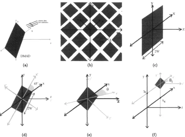
Figure 1. (a) Coordinate system selected for the analysis of the light field by DMAD (b) Top view of DMAD in the
coordinate system of fig. 1(a) (c) Problem analyzed in sec. 3.1. Mirror edges areparallelto coordinate axes. (d) Problem
analyzed in sec. 3.2. (e) Problem analyzed in sec. 3.3. (f) Problem analyzed in sec. 3.4.
Inserting Eq. 20 into Eq. 18 and Eq. 21, we recognize that
q('Gi) (x) =
exp{izkTTI}oei
(x — T1)=
exp{ikTTI}aO
K (R91(x —T1)) (22) 0O 4. N . (b) (a)12*
(c) (d) (e) (f)which is the most general case we set out to handle.
4. TOTAL COMPLEX LIGHT FIELD PRODUCED BY DMAD
By virtue of Eq. 22 and the superposition assumption of section Eq. 1, the light field produced by the DMAD, upon incident illumination by the monochromatic plane wave exp {jkTx} is:
u(x) =
:
(x) =
: exp
{iEKTTi}/,aojk (Ret (x —Ti))
(23) This result is for the coordinate system depicted in fig. 1(a). Explicit expressions of matrices T1 and R9 areprovided in Eq. 1 and Eq. 19, respectively. Explicit expressions for the 6-parameter function (x) of Eq. 2 are discussed in subsection Eq. 3.1.
Figure 1. (a) Coordinate system selected for the analysis of the light field by DMAD (b) Top view of DMAD in the
coordinate system of fig. 1(a) (c) Problem analyzed in sec. 3.1. Mirror edges are parallel to coordinate axes. (d) Problem analyzed in sec. 3.2. (e) Problem analyzed in sec. 3.3. (f) Problem analyzed in sec. 3.4.
Inserting Eq. 20 into Eq. 18 and Eq. 21, we recognize that
q(iOi) (x) =
exp{izTT1}oei (x —
T1)=
exp{
jIcTTi}a
K(R91(x —Ti))
(22)—
.: F N S (b) (a) (c) (d) (e) (f)REFERENCES
1. J. W. Goodman. Introduction to Fourier Optics. Mc-Graw-Hill, New York, 1996.
2. R. J. Gove. DMD display systems: the impact of an all digital display. In mt Symp Society for Informa-tion Display, page http://www.ti.com/dlp/docs/developer/resources/white/index.shtml. Texas Instruments
White Pages, 1994.
3. L. J. Hornbeck. Digital light processing update: status and future applications. In Conf on Projection
Displays V, Proc SPIE, volume 3634, pages 158—170, 1999.
4. R. S. Nesbitt, S. L. Smith, R. A. Molnar, and S. A. Benton. Holographic recording using a digital micromirror device. In S. A. Benton, editor, Conf on Practical Holography XIII, Proc SPIE, volume 3637, pages 12—20,
1999.
5. T. Kreis, P. Aswendt, and R. Hofling. Hologram reconstruction using a digital micromirror device. Optical Engineering, 40:926—933, 2001.
REFERENCES
1. J. W. Goodman. Introduction to Fourier Optics. Mc-Graw-Hill, New York, 1996.
2. R. J. Gove. DMD display systems: the impact of an all digital display. In mt Symp Society for Informa-tion Display, page http://www.ti.com/dlp/docs/developer/resources/white/index.shtml. Texas Instruments
White Pages, 1994.
3. L. J. Hornbeck. Digital light processing update: status and future applications. In Conf on Projection
Displays V, Proc SPIE, volume 3634, pages 158—170, 1999.
4. R. S. Nesbitt, S. L. Smith, R. A. Molnar, and S. A. Benton. Holographic recording using a digital micromirror device. In S. A. Benton, editor, Conf on Practical Holography XIII, Proc SPIE, volume 3637, pages 12—20,
1999.
5. T. Kreis, P. Aswendt, and R. Hofling. Hologram reconstruction using a digital micromirror device. Optical Engineering, 40:926—933, 2001.