Synthesis of Titania nanotubes/polyaniline via rotating bed-plasma
enhanced chemical vapor deposition for enhanced visible light
photodegradation
M.N. Subramaniam
a, P.S. Goh
a,⁎, W.J. Lau
a, A.F. Ismail
a, M. Gürsoy
b, M. Karaman
b aAdvanced Membrane Technology Research Center, Faculty of Chemical and Energy Engineering, Universiti Teknologi Malaysia, 81310 Skudai, Johor bDepartment of Chemical Engineering, Selҫuk University, 42031 Konya, TurkeyA R T I C L E I N F O
Keywords: Conductive polymer Visible light photocatalysis Titania nanotubes Photocatalyst
A B S T R A C T
This study employed rotating bed plasma enhanced chemical vapor deposition technique to coat a thin poly-mericfilm of polyaniline (PANI) onto titania nanotubes (TNT). The effect of plasma power on the growth of thin film polymer on the photocatalyst surface was investigated. Transmission electron microscope micrographs evidenced the formation of thin polymeric layers on TNT surface. Fourier-transform infrared spectra confirmed the presence of functional groups associated with PANI. The band gap of coated photocatalyst reduced from 3.23 eV to 2.54 eV, implying the photosensitivity of TNT-PANI in visible light range, while photoluminescence spectra showed that PANI coated TNT exhibited lower recombination rates. The photocatalytic performance of the resultant TNT-PANI titania were evaluated under both UV and visible light irradiation using reactive black 5 (RB 5) as the model pollutant. Unlike TNT which could only be activated under UV light, TNT-PANI coated using a plasma power of 50 W exhibited superior photoactivity under both ultraviolet (UV) and visible light irradia-tion. The incorporation of PANI enhanced UV light photodegradation performance, where reaction rate im-proved to 0.615 ppm min−1and three times higher compared to uncoated TNT. The best sample TNT-PANI 50 W exhibited promising photodegradation efficiency of 56.4% within 240 min of visible light irradiation.
1. Introduction
Polymer science is an intriguing area with vast potential for real-world applications in thefields of engineering, from drug delivery to synthesis of composite materials. One research area that has been gaining popularity since its discovery by Shirakawa et al. [1] is the development of conducting polymers. Conductive polymers are organic polymers with conjugated double bonds, alternating single and double bonds and the availability of electron richπ bonds [2]. Rarely seen in other polymers, the structure of conductive polymers provides free electrons to conduct electricity and improve electrochemical activity. The unique properties exhibited by conductive polymers are very va-luable for the development of dielectric materials and sensors [3]. Furthermore, their electric conducting properties can also be combined with metals or semiconductors to produce highlyflexible and durable composite conductors compared to metal only conductors [4]. The commonly studied conducting polymers in both fundamental research and industry application are polyaniline (PANI), polypyrrole (PPy), and polythiophene (PT) [5]. Significant attempts have been focused on
understanding the polymer nanostructures for energy conversion and storage application [6]. Recently, conducting polymers have also gained considerable interest in thefield of photocatalysis due to the synergistic effect obtained from the composite system [7].
Photocatalytic properties exhibited by semiconductors such as TiO2,
Fe2O3and ZnO allow photodegradation of various types of pollutants
[8–10]. Photocatalysts harvest photons from ultraviolet (UV) light source to enable electron excitation and subsequently form oxidative species such as hydroxyl radicals and oxygen radicals to degrade pol-lutants. One of the strategies to further improve and widen the appli-cation of photocatalyst is photocatalyst modifications through doping [11]. Doping of photocatalyst involves the introduction of foreign atoms into the lattice structure or on the surface of semiconductor photocatalyst to promote the conventionally used photocatalyst to be responsive towards visible light irradiation [12,13]. In addition, doping can also reduce the band gap energy and suppress electron-hole re-combination by providing an electron vacancy site [14,15]. Doping can be feasibly carried out by introducing metallic atoms such as iron [16], cobalt [17], tungsten [18] and non-metallic atoms such as nitrogen
https://doi.org/10.1016/j.apsusc.2019.04.118
Received 17 December 2018; Received in revised form 24 March 2019; Accepted 9 April 2019
⁎Corresponding author.
E-mail address:[email protected](P.S. Goh).
Available online 10 April 2019
0169-4332/ © 2019 Elsevier B.V. All rights reserved.
[19] and sulphur [20]. Incorporation of conductive polymer onto photocatalysis can bring about the same effect as photocatalyst doping. The availability of conjugated single and double bonds with electron-rich sites can favorably improve electron promotion to initiate photo-catalytic activity and act as an electron charge carrier [21]. The effect of conducting polymers on photocatalytic activity of traditional semi-conducting photocatalysts like TiO2[22,23], Fe2O3[24] and MgFe [25]
have been reported. These studies demonstrated the feasibility of using conducting polymers to enable visible light photocatalytic degradation of various pollutants. Gu et al. [26] discovered that coating PANI on the photocatalyst surface can suppress agglomeration of TiO2
photo-catalyst. This feature is desired to address the limitation of high surface area photocatalyst such as titania nanotubes (TNT). Mustafin [22] showed that the attachment of PANI onto TiO2 surface was able to
improve the photocatalytic performance in two-fold. In the above-mentioned studies, PANI was coated via chemical oxidative methods or oxidations chemical vapor deposition to polymerise aniline onto the photocatalyst surface. The combination of TiO2nanoparticles and TiO2
nanobelts with PANI has also been used for the photocatalytic de-gradation of methyl orange (MO) and RB 5. The stable performance of these PANI modified TiO2after several cycles of operations indicated
the great photocatalytic stability [27,28]. Despite the promising results, the major drawbacks of these techniques are the usage of liquid che-micals and multiple steps for uniform polymerisation [29]. Further-more, it is very difficult to achieve uniform particle coating without agglomeration with liquid-based methods, especially for particle sizes below 100μm.
In this work, a sealed and vacuumed rotating-bed plasma enhanced chemical vapor deposition (RB-PECVD) system was used to grow PANI on the surface of TNT to produce PANI-coated TNT of high purity via plasma deposition. PECVD technique does not use liquid medium, as the monomer is elevated into gaseous phase via heating, which allows uniform coating onto any substrate. PECVD has been widely used for coating and encapsulation of drug particles [30], carbon nanotubes [31], and aluminium nanoparticles [32]. However, the employment of PECVD to coat photocatalysts with conducting polymer is still scarce. Our previous studies have evidenced the excellent photocatalytic ac-tivity of TNT compared to its TiO2counterpart [33]. The introduction
of PANI coating onto TNT surface is expected to impart visible light photosensitivity on TNT and improve the photocatalytic performance for more practical application. The utilisation of RB-PECVD can pro-duce conformal and structurally well-defined thin films on TNT while producing pure thinfilms as the monomers are vaporised and carried into the reaction chamber without any carrier gas, eliminating any contaminants. The vacuum condition generated also ensures no foreign particles are involved in the reaction process. In this study, character-istics of PANI coated TNT photocatalyst such as morphology, polymer film thickness, functional groups, crystallinity and light absorption capabilities were studied. The effect of plasma power on the properties and characteristics of PANI coated TNT was also investigated. Finally, the role of PANI in enhancing the photocatalytic activity of TNTs was explored.
2. Methodology
2.1. Materials
Titanium dioxide (CAS No: 13463-67-7) used for this study was sourced from Evonik Industries (TiO2P25 Degussa) as the precursor for
the synthesis of TNT. Both hydrochloric acid (HCl, ACS reagent, 37%, CAS No: 7647-01-0) and sodium hydroxide (NaOH, ACS reagent, ≥97.0%, pellets, CAS No: 1310-73-2) used in the synthesis of TNT were purchased from Sigma Aldrich. Reverse Osmosis (RO) water was used for washing in the synthesis of TNT. Aniline (ACS Reagent,≥99.5%, CAS No: 62-53-3) and Reactive Black 5 (RB 5, C26H21N5Na4O19S6,
λmax= 585 nm dye content ≥50%, CAS No: 17095–24-8), isopropyl
alcohol (IPA) (FCC≥99.7%, CAS No: 67–63-0) and p-benzoquinone (Reagent Grade,≥98%, CAS No: 106–51-4 were also procured from Sigma Aldrich. Aluminium oxalate (CAS No: 6009-70-7) was procured from SYSTERM®. Ultrapure water was used to produce dye solutions of known concentrations. All the materials were used as received without further modification or purification. Whatman PTFE membrane filter (0.45μm) coupled with 15 ml disposable plastic syringes were used to separate the photocatalyst from aqueous sample solutions before ana-lysis.
2.2. Synthesis of TNT
The synthesis of TNT has been described in detail in our previous work [33]. Briefly, 3 g of the TiO2were dispersed in 120 ml 10 M of
NaOH and stirred for 4 h. Next, the mixed solution was transferred into a Teflon lined container, and subsequently placed into an autoclave steel block and closed tightly. The autoclave was then transferred to an oven which was preheated to 180 °C and left inside for 24 h for hy-drothermal reaction to commence. After the reaction time has passed, the autoclave wasfirst cooled down before opening it to retrieve the treated sample. The sample was then washed with tap water to remove residual NaOH, then with 0.1 M HCl andfinally with tap water again till the pH of the decanter water reached pH 7. The sample wasfiltered using afilter paper, dried at 60 °C, and finally ground to obtain fine particles.
2.3. Surface modification of TNT with PANI
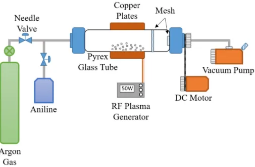
The synthesized TNT was used as a substrate for deposition of PANI thinfilms via RB-PECVD. The schematic of the RB-PECVD used in this study is illustrated inFig. 1.The system set-up was adopted from the work reported by Gürsoy and Karaman [34]. Briefly, 1 g of TNT was placed in the middle of a Pyrex cylindrical glass tube with a diameter of 6 cm and a length of 30 cm. The glass tube was then clamped in its place. The monomer was placed in its container (stainless steel jar) and clamped to the manifold pipeline to feed in the reactor. Theflowrate of monomer was controlled using a needle valve. Next, the vacuum pump was turned on to remove air and to create a vacuum environment in the reaction tube. Argon gas was used to degas TNT and purge out im-purities for a duration of 30 min, followed by the introduction of monomer vapor into the reaction chamber. The plasma was then turned on at a stabilised pressure of 100 mTorr. The non-thermal plasma dis-charge in the reactor was generated by a 13.56 MHz radio frequency (RF) power source. The reaction time was set at 10 min with a monomer flow rate of 0.67 sccm, at a rotation direction of counter-clockwise. Rotation of TNT In Pyrex cylindrical glass is important as it provides agitation and continuous explosure towards plasma gases. When reac-tion time has elapsed, the plasma was turned off and PANI-coated TNT was collected from the reaction chamber. Plasma powers of 25 W, 50 W and 75 W was used to study the effect of plasma power on the chemical structure and thickness of PANI thinfilms on TNT surface. The samples were then characterised for their morphology, chemical functional groups identification, surface area, crystallinity, atomic composition and light absorption capabilities.
2.4. Characterization of PANI coated TNT
Characterizations of the as-prepared samples were done to study the characteristics and interaction between photocatalyst and conductive polymers. TEM analysis (JEOL JEM-2100Plus Transmission Electron Microscope) was conducted to observe the formation of polymer thin film on TNT and to determine the thickness of deposited PANI layers. Samples were dispersed in water and a drop of the suspension was placed on a copper grid and left overnight to allow water to vaporise. Attenuated total reflectance (ATR) FTIR spectra (Thermo Scientific Nicolet 380) were obtained in wavenumbers range of 500 and
4000 cm−1at a resolution of 4 cm−1. BET analysis was performed using a Micromeritics TriStar II PLUS, with nitrogen used as adsorbate gas. XRD analysis (Bruker D8 Advance) was conducted at a glancing angle of 5°. UV–Vis NIR (Hitachi-U4100 V–vis-NIR spectrophotometer 341-F) analysis was conducted to calculate the change in the band gap of PANI coated TNTs. The band gap changes of coated TNT were determined using the Tauc's relation [35];
= −
ahv A E( g hv)n
where A is a constant, a is the absorption coefficient, Egis the average
band gap of the semiconductor, ‘n’ depends on transition type, h is Plank's constant (6.626 × 10⁻³⁴Js−1), and n is the frequency of pho-tons, and v is the frequency of the photons. The band gap of all the TNT-PANI prepared was determined from the tangent of the line in the (ahv)2vs. hv graph [36]. The photoluminescence spectra of uncoated
and coated TNT were analysed using a PerkinElmer, LS 55. The samples were blow-coated on translucent tape placed on a glass slide.
2.5. Adsorption of RB 5 onto TNT-PANI
The adsorption studies of RB 5 adsorption onto TNT-PANI were done to determine the adsorption capacity of as-prepared samples. 0.2 g of prepared sample was added in 200 ml of 10 ppm RB 5 and stirred at a speed of 300 rpm in dark conditions and in room temperature (25 °C). The experiment was conducted in dark condition to ensure no photo-catalysis occurs. Aqueous samples of 10 ml were collected after 30 min to determine the adsorption equilibrium. The samples were collected using a 15 ml syringe and filtered using a Whatman 0.45 μm PVDF membranefilter to remove any suspended nanomaterials. The filtered aqueous samples were the analysed using a Shimadzu UV mini-1240 UV–Vis Spectrophotometer at a determined wavelength of λ = (493 nm) based on the wavelength absorption peak of RB 5 in aqueous form. The adsorbed amount of RB 5 at equilibrium Qe(mg g−1)
was calculated by the following Eq.(1):
= −
Q C C V
W
( )
e o e (1)
where Coand Ce(mg/l) are the initial and equilibrium concentrations of
RB 5 solution respectively, V(L) is the volume of solution, and W(g) is the weight of the TNT-PANI samples used during adsorption experi-ments.
2.5.1. Photoactivity of PANI coated TNT
The role of PANI in improving the photocatalytic activity of TNTs was investigated based on its ability to degrade RB 5 dye in aqueous form. The experiments were conducted under both UV and visible light conditions. A Philips PL-L 24 W 4 pin UV-A and a Philips PL-L 24 W 4 pin Daylight 4500 Kfluorescent light were used as UV and visible light source respectively. The distance of light source from aqueous solution was maintained at 2 cm, while the samples were stirred constantly at a speed of 300 rpm throughout the experiment to provide constant agi-tation. The experiment was conducted in an aluminium foil-coated chamber to prevent photons from escaping. The schematics of the re-actor is illustrated inFig. 2.
The photocatalytic experiment procedure follows our previous work [33]. Briefly, 200 ml of RB 5 10 ppm were added into a 250 ml glass beaker, followed by the addition of 0.2 g of photocatalyst (1 g/L) and placed on a magnetic stirrer located inside the reaction chamber. The sample is stirred for 30 min to achieve adsorption equilibrium. The light source (visible or UV) is then turned on to initiative photocatalysis. The photocatalytic reaction was allowed to happen for 6 h. The change in dye concentration was determined by a UV spectrophotometer (Shi-madzu UV mini-1240 UV–Vis Spectrophotometer) using a glass cuvette. The photocatalytic degradation of RB 5 was determined based on Eq. (2):
Fig. 1. Schematic diagram of RB-PECVD used for the fabrication of TNT-PANI.
Fig. 2. Schematics diagram of the photocatalytic reaction set up to degrade RB 5.
= − ×
D C C
C 100
0
(2) where D is the degradation efficiency, C is the initial concentration of RB 5, Cois thefinal concentration of RB 5. The photoactivity and
de-gradation efficiency of all the TNT-PANI samples prepared in this study were evaluated. Additionally, the reusability of the photocatalyst were studied by conducting degradation studies for 5 cycles with the same photocatalyst.
Radical scavenger studies were also conducted to investigate the active species produced by the photocatalyst and involved in photo-degradation of RhB. The scavenging experimental procedure was si-milar to the photocatalytic degradation experiments but isopropyl al-cohol (IPA) (0.1 ml) (%OH radical scavenger), ammonium oxalate (hole scavenger) (0.1 g) and 4-benzoquinone (superoxide radicals) (1 mg) were added into the as-prepared dye solution prior to addition of photocatalyst. The photocatalytic degradation in the presence of var-ious radical scavengers was calculated using Eq.(2).
2.5.2. Photocatalytic kinetics
The photocatalytic degradation of RB 5 obeys the pseudo-first-order kinetics in terms of modified Langmuir- Hinshelwood (L-H) model shown in Eq.(3); = − = + r dc dt k K C K C 1 r LH LH (3)
In this equation, r (mg/l min), kr(mg/l min), KLH(l/mg), C (mg/l)
and t (min) are the reaction rate, reaction rate constant, adsorption constant, reactant concentration and time of illumination, respectively. When C is very small, Eq.(2)can be written in form of Eq.(4);
= − = =
r dc
dt k Kr LHC kc (4)
where k (min−1) is the pseudo-first-order rate constant. During pho-tocatalytic activity, the dye adsorbed onto the surface of nanotubes will reach an equilibrium of adsorption-desorption after 20 min. The equi-librium of the dye solution was used as the initial dye concentration for the kinetic analysis Co. Both equations are integrated with the limit of
C = Coat t = 0 and C = Ctat time t gives Eq.(5);
= − C
C kt
ln
o (5)
where the plot-ln(C/Co) versus t for all nanotubes are linear and the
value kapp(apparent rate of reaction) can be obtained directly from the
slope.
2.5.3. Sample analysis
The concentration of aliquots collected during all experiments was analysed using a UV–Vis spectrophotometer to obtain UV–Vis diffuse reflectance spectra of RB 5 based on its maximum absorbance wave-lengthλ = 493 nm. A series of RB 5 with known concentrations of 2, 4, 6, 8, and 10 ppm was prepared to obtain a calibration graph and the concentration (ppm) of samples collected was determined using the straight-line equation (R2= 0.996) shown in Eq.6:
= −
y 0.0277x 0.0039 (6)
where y is the absorbance value and x is the concentration of RB 5.
3. Results and discussion
3.1. Characterization of TNT-PANI
Visibly, the physical appearance of TNT turned from white into a light-yellow hue upon the coating of PANI as can be seen in Fig. 3. Fig. 4shows the TEM micrographs of TNT and prepared TNT-PANI.
The micrographs displayed in Fig. 4(b–d) show the presence of open-ended TNT with uniform PANI coatings. It was also observed that
the coatings covered all sides of TNT surface, including lumen opening. Compared to conventionally used oxidative polymerisation which commonly resulted in uneven coating thickness (Gilja et al. [7]), uni-form PANI coating across TNT surface was achievable using RB-PECVD under vacuum conditions. Another advantage of RB-PECVD is that it avoids excessive growth of PANI sheets that may agglomerate TNT and hinder its photocatalytic properties [37]. It was also observed that there was a reduction in polymer thinfilm thickness with an increment of plasma power employed during the synthesis. The thickness of TNT-PANI 25 W, TNT-PANI 50 W and TNT-PANI 75 W is 8.386 ± 0.2389 nm, 1.826 ± 0.4212 nm and 1.215 ± 0.414 nm, re-spectively. It is well known that at higher plasma power, the kinetic movement of monomer radicals increases and the constant bombard-ment of radicals on the substrate surface during plasma polymerisation may induce ablation effect [38]. Momentum during the bombardment of ions may transfer kinetic energy to a surface atom that is directed away from the surface. The surface atom may have acquired enough energy to overcome the surface binding energy and escape from the solid surface [39]. This phenomenon leads to lower thinfilm thickness with increasing plasma power which was observed in this study. Gürsoy and Karaman [40] have observed a similar trend when they coated hydroxyethyl methacrylate on perlite particles via PECVD.
The FTIR peaks of TNT, PANI 25 W, PANI 50 W and TNT-PANI 75 W were collected in the range of 500 to 4000 cm−1and are displayed inFig. 5, while the functional groups that are present in PANI coated TNT are presented inTable 1. PANI consists of repeating units of benzene rings and an amine functional group whereas TNT is covered with OHe and COOHe functional group, making them rich with hy-droxyl functional groups.Fig. 5 also shows the appearance of char-acteristic peaks at 1217.54 cm−1, 1367.28 cm−1, 1443.01 cm−1, 1738.45 cm−1and 3021.68 cm−1present in PANI coated TNT (b–d) whist these peaks were absent in uncoated TNT (a). These peaks can be ascribed to the functional groups of PANI. The peaks of 1217.54 cm−1, 1367.28 cm−1and 1443.01 cm−1are designated to CeN stretching of the benzenoid ring which is present in the structure of PANI [41]. The peak at 1635.18 cm−1can be observed at both TNT and PANI coated TNT, but the intensity decreased as the plasma power was increased. This peak can be associated to C]N stretching of the quinoid ring [42], which is also present during the formation of PANI emeraldine base. Additionally, the broad OHe peak is present in all three PANI coated TNT in discussion, which indicates that PANI coating did not com-pletely suppress the hydroxyl functional groups that were abundantly available on TNT surface. It can then be deduced that the hydrophilicity of TNT has been conserved during the surface coating. It is highly de-sirable to introduce coating layers onto photocatalyst without in-hibiting the loss of its surface hydroxyl functional groups. These func-tional groups are important to allow attachment of water molecules onto the surface of the photocatalyst, as water is broken down to form reactive radicals [43].
Fig. 6shows the XRD spectra of TNT and TNT-PANI synthesized using different plasma powers. The position of the peaks of TNT-PANI samples is found to closely resemble that of uncoated TNT. It has been reported that the characteristic peak of PANI polymer appears at 2θ = 25.27ᴼ, which overlaps with the characteristic peak of TNT [44]. The intensity of peaks presents in XRD spectrums displayed inFig. 6is similar to uncoated TNT. As the intensity of XRD peaks is highly gov-erned by the crystalline structure of TNT rather than PANI itself, the observation suggested that the crystallinity of TNT was well conserved during the coating process. Interestingly, the peaks at 2θ = 10.53° and 24.89° present in uncoated TNT have been slightly shifted to 2θ = 11.67° and 25.37°, respectively in all TNT-PANI samples [25]. There are two factors contributing towards the XRD peak shifting, i.e. the strain on the surface and the changes in chemical composition [45]. The presence of thin layered PANI can cause planar stress, consequently shifted the XRD peaks to higher degrees, which is also the case in this study. Similar shifting has been observed in PANI coated ZnO
nanoparticles [25].
Fig. 7shows the UV–Vis near-infrared analysis of TNT and TNT-PANI coated at different plasma powers. When compared to uncoated TNT, PANI-TNTs showed visible light absorption from the wavelength of 350 nm to 550 nm, whist uncoated TNT did not absorb any light in the visible light region. Furthermore, the band gap of uncoated TNT and coated TNT-PANI were evaluated by measuring their diffuse re-flectance spectra and calculated using Tauc's plot for all the PANI coated TNT [35]. The calculated band gaps showed a decreasing trend, from 3.232 eV for TNT and 2.543 eV for TNT-PANI 75 W. The reduction in the band gap of TNT-PANI compared to uncoated TNT indicated possible visible light activation due to the narrowing of wavelength absorption capabilities of surface modified nanotubes [46]. The coating of heterojunction conducting polymer such as PANI onto nanotube structure works as a photosensitizer to absorb visible lights [24]. It allows visible light inducedπ − π* electron transition from lower un-occupied molecular orbitals (LUMOs) of PANI chains to the conduction bands (CB) of TNT. The electrons are then transferred to the surface of this composite catalyst to react with water and oxygen, subsequently forming O2%−radicals to oxidise the dye particles [23]. In this
me-chanism, PANI works as a great electron donor by donating electron into the CB of TNT to activate redox reaction, hence less energy is re-quired to activate the photocatalysis [29]. Previous studies have shown that, despite its outstanding electron conducting properties, pure PANI did not act as an efficient photocatalyst mainly due to its high electron-hole recombination rate [47]. In this p-n heterojunction photocatalyst, the metallic nature of TNT is important to allow PANI to act as a pro-mising photocatalyst. TNT works as an electron trapping site and also is
an effective interfacial contact between PANI matrix and TNT to form heterojunctions, creating a synergistic effect in enhancing the photo-catalytic activity under visible light. Fig. 8 shows the photo-luminescence spectra of TNT and TNT-PANI coated at different plasma power. Photoluminescence (PL) analysis was conducted to study the efficiency of charge carrier trapping, immigration transfer and to
Fig. 3. Physical appearance of a) TNT, b) TNT-PANI 25 W, c) TNT-PANI 50 W and d) TNT-PANI 75 W which shows colour changes after coating.
Fig. 4. TEM micrographs of a) TNT, b) TNT-PANI 25 W, c) TNT-PANI 50 W and d) TNT-PANI 75 W.
Fig. 5. FTIR Spectra of a) TNT, b) TNT-PANI 25 W, c) TNT-PANI 50 W and d) TNT-PANI 75 W.
understand the recombination of electron-hole pairs in semiconducting nanomaterials [48].Fig. 8shows the PL analysis of uncoated TNT and PANI coated TNT at different plasma power.
Thefigure exhibits the reduction in PL intensity for both TNT-PANI 25 W and TNT-PANI 50 W as compared to the spectra exhibited by uncoated TNT whilst TNT-PANI 75 W exhibited a similar spectrum as compared to the uncoated TNT. Additionally, a new peak was formed at wavelength 327 nm, which can be ascribed to the presence of PANI thin
film as also observed by Ninh et al. [49]. The lower PL intensity ex-hibited by TNT-PANI 25 W and TNT-PANI 50 W points to the fact that the recombination rate has been suppressed as compared to uncoated TNT [50], which is favourable for enhancing the photocatalytic ac-tivity. The reduction in electron-hole recombination rate was due to the conjugatedπ–π structure of PANI which has facilitated charge transfer from TNT to PANI [51]. The PL results also suggested that the photo-induced electrons and holes were trapped in the overlapping energy level of TNT and PANI. With the suppression of the electron-hole re-combination, the production of reactive oxidative species (ROS) could be enhanced to improve the photocatalytic reaction. TNT-PANI 75 W showed the strongest peak exhibited at 327 nm compared to PANI-TNT 25 W and PANI-TNT 75 W, reaffirming the adverse effect of thick PANI coating on TNT (Fig. 9).
The specific surface area of TNT is 140.232 m2
/g, with pore volume at 0.842 cm3/g and an average pore size of 11.001 nm. However, these
properties were expected to change when PANI was coated onto the surface of TNT. There was no clear trend with the changes incurred on the surface area of TNT-PANI samples. TNT-PANI 25 W exhibited the lowest specific surface area at 89.229 m2/g, while both TNT-PANI 50 W
and TNT-PANI 75 W showed a reduction in specific surface area to 123.890 m2/g and 113.164 m2/g respectively as compared to uncoated TNT. It was also noticeable that the pore size and pore volume of both TNT-PANI 25 W and TNT-PANI 50 W increased compared to those of uncoated TNT. Such observation contradicts to previous study that has reported the decrease in surface area and pore volumes upon PANI coating using chemical technique [52]. This shows that RB-PECVD technique can coat particles without compromising pore size and pore volume. Reduction in pore size and pore volume was only exhibited by TNT-PANI 75 W. The reduction in pore volume with high plasma power can be attributed to the ablation effect. High plasma power has created large numbers of kinetically charged polymer radicals that penetrated nanotube pores for deeper coating. Hence, continuous coating at high plasma power would reduce the pore volume, as seen in TNT-PANI 75 W. This is supported by the fact that the average pore size of TNT-PANI 75 W is smaller compared to uncoated TNT.
3.2. Coating mechanism
Fig. 10shows the schematic illustration of plausible coating me-chanism of PANI thinfilms on the nanotube surface.
The plasma power in the range of 25–75 W generated sufficient energy to ionise aniline monomers present in the reaction chamber to initiate polymerisation on TNT surfaces. PANI thinfilms were evenly formed during the polymerisation process in PECVD. The polymerisa-tion continued until the plasma was turned off. With the continuous flow of monomers into the reaction chamber to complete the poly-merisation process, the defects present on thinfilms were sealed. It is theorised that the polymer chain continued to grow on the nanotubes surface with time. However, higher plasma power would induce abla-tion for PANI, as observed in the TEM micrographs displayed inFig. 4, forming thinnerfilms on the substrate surface. High plasma power can produce high numbers of kinetically charged polymer radicals, and this reduces the thickness of polymer thinfilm at higher plasma power, as
Table 1
Functional groups present in PANI coated TNT.
Wavenumber (cm−1) Peak wave number Functionality
650–750 681.47 CeC, CeH Bonding mode of the aromatic ring
1230–1310 1217.54, 1367.28 CeN stretching of benzenoid ring
1503–1511 1443.01 C]C stretching of benzenoid ring
1570–1595 1635.18 C]N Stretching of quinoid ring
1738.45 Carbonyl group (CeO) stretching vibrations
2800–3000 3021.68 Symmetric stretch vibration band of methylene [e(CH2)ne] and methyl e(CH3)
3000–3500 – OH-Stretching and bending
Fig. 6. XRD spectra of a) TNT, b) TNT-PANI 25 W, c) TNT-PANI 50 W and d) TNT-PANI 75 Wθ.
Fig. 7. UV–Vis NIR spectra of all a) TNT, b) TNT-PANI 25 W, c) TNT-PANI 50 W and d) TNT-PANI 75 W and its respective band gap values.
Fig. 8. Photoluminescence spectra of a) uncoated TNT and b) PANI coated TNT at different plasma power.
Fig. 9. Specific surface area, pore volume and average pore size data of all the nanotubes in this study.
Fig. 10. PANI coating mechanism onto the nanotube surface via RB-PECVD.
observed in TEM micrographs.
3.3. Adsorption and photocatalytic kinetics of TNT and PANI-TNT As adsorption and photocatalysis occur simultaneously during the pollutant degradation process, it is important to understand the role of adsorption to determine the actual photocatalytic activity efficiency
[53]. Fig. 11shows the RB 5 adsorption capacity of TNT and PANI coated TNTs.
Adsorption capacity is referred to as the total amount in mg of a pollutant that is adsorbed on per g of adsorbate. TNT is known to be highly porous, with a specific surface area of around 200 m2/g based on
our previous research [33]. However, all the nanotubes prepared in this study have shown relatively low adsorption capacity on RB 5. From Fig. 11, both TNT-PANI 25 W and TNT-PANI 50 W showed the best adsorption capacity of 2.3 mg/g, with TNT performing better compared to TNT-PANI 75 W. It has been evidenced that RB 5 dye particles also showed poor adhesion onto other absorbents such as chitosan and TiO2
[54,55].
Photocatalytic activity exhibited by TNT and TNT-PANI prepared in this study was evaluated by its ability to degrade RB 5, an azoic dye in its natural pH conditions. The effect of plasma power onto the photo-catalyst activity of nanotubes and its photoactivity under both UV and visible light was evaluated. Fig. 12(a) represents the degradation
Fig. 12. a) Photocatalytic degradation kinetics of TNT and TNT-PANI and b) degradation of RB 5 under UV light.
Fig. 13. a) Photocatalytic degradation kinetics of TNT and TNT-PANI and b) degradation of RB 5 under visible light conditions.
Table 2
Photocatalytic degradation of dye pollutants by various titania/PANI compo-sitions.
Catalyst Technique Pollutant Efficiency References
PANI/TNT PECVD RB 5 56.39% This study
PANI nanofiber with TiO2
Chemical method and hydrothermal
Rhodamine B 90% [26] PANI/TiO2 Chemical method Methylene blue 88% [56]
Fig. 14. a) Radical scavenging with IPA, aluminium oxalate and p-benzoquinone using PANI-TNT 50 W photocatalyst and b) photocatalytic experiments of TNT-PANI 50 W for 5 cycles under visible light.
kinetics while (b) represents the degradation evolution of various TNT and TNT-PANI under UV light source.
Results displayed inFig. 12(b) showed that TNT-PANI 50 W out-performed other samples under UV light irradiation in terms of pho-tocatalytic degradation rate. TNT-PANI 50 W was able to perform > 90% dye degradation within 130 mins, while TNT-PANI 25 W was able to achieve the same degradation performance within 150 min. On the other hand, TNT achieved 90% pollutant degradation after 180 mins of UV irradiation. The pollutant degradation rate was improved by 33% with TNT-PANI, indicating that the presence of PANI has synergistically improved the photocatalytic efficiency of TNT. However, it is inter-esting to note that TNT-PANI 75 W did not exhibit any photocatalytic activity under UV light irradiation. When the photocatalyst is irradiated with either UV or visible lights, the photon is absorbed to produce pairs of electrons and holes. These charge carriers are able to recombine, or the holes can be scavenged by oxidizing species and electrons by re-ducible species in the solution, whichfinally, lead to the destruction of RB 5 pigment molecules. The poor photocatalytic performance ex-hibited by TNT-PANI 75 W may be attributed towards the polymerisa-tion of PANI onto TNT at very high power. Increase in plasma power would lead towards quicker polymerisation. A high amount of PANI on TNT surface prevented the photocatalyst from absorbing visible light, thus causing a rapid decrease of photons passing through the reaction system [23]. Based on the results, a plasma powered at 50 W can be ascribed as the threshold value for plasma polymerisation for the creation of visible light sensitive TNT photocatalyst. All the data cal-culated followed a first-order reaction model, and the calculated ap-parent kinetic rate constants (kapp) are summarized in the table
in-corporated inFig. 12(a). All the experimentsfit the pseudo first-order kinetic with R2≥ 0.99 except for TNT-PANI75 W. TNT-PANI50
de-monstrated the highest degradation rate of 0.615 ppm min−1, which was almost 3 times higher compared to TNT. Fig. 13 displays the photocatalytic degradation kinetics of TNT and TNT-PANI and de-gradation of RB 5 under visible light conditions.
TNT is known to be unresponsive towards visible light due to their large band gap (> 3.2 eV), as evidenced by the negligible removal of RB 5 which was mainly due to adsorption on TNT surface. Both TNT-PANI 25 W and TNT-TNT-PANI 50 W exhibited RB 5 photodegradation ef-ficiency of 48.5% and 56.4% respectively under visible light irradiation within 240 min. The photoactivity exhibited by TNT-PANI 25 W and TNT-PANI 50 W under visible light conditions supports the fact that the introduction of PANI onto TNT surface has allowed visible light capture and electron transition to accelerate the formation of hydroxyl radicals. TNT-PANI 50 W showed better photoactivity under visible light com-pared to TNT-PANI 25 W, with an apparent rate of reaction of 3.19 × 10⁻²ppm/min compared to 2.64 × 10⁻²ppm/min. PANI has an abundance of conjugated single and double bonds with electron-rich sites which can favorably improve electron promotion to initiate pho-tocatalytic activity and act as an electron charge carrier. The synergistic
effect and the good interface between PANI and the surface and TNT allowed rapid charge transfer, charge separation and slow charge re-combination of the photocatalyst, all contributing towards the im-proved photocatalytic activity exhibited by PANI coated TNT's under visible light irradiation. When TNT-PANI was irradiated with visible light, the photocatalyst absorbed the photons to generate electron-hole pairs, The excited electrons migrated into the conduction band of TNT, subsequently transferred to the surface of the photocatalyst and reacted with water to create superoxide radicals which in turn oxidised all or-ganic molecules adsorbed on the surface. The electrons in the VB of TNT were transferred into the PANI and left with holes, which yielded hydroxyl and superoxide radicals on the surface of TNT, leading to the enhanced photocatalytic activity. The results showed that the in-corporation of PANI onto the surface of TNT increase the photocatalytic activity under both UV light and visible light irradiation.Table 2shows the photocatalytic degradation of dye pollutants by various titania/ PANI compositions.
The radical trapping properties of PANI-TNT 50 W were in-vestigated to further understand the dominant photocatalytic activity mechanism exhibited by the photocatalyst. As shown in Fig. 14a), aluminium oxalate, isoproterenol (IPA), and p-benzoquinone (BQ) were used to capture the hole (h+), hydroxyl radical (%OH) and %O2−, re-spectively As elucidated inFig. 14(a), the addition of aluminium ox-alate has greatly reduced the photocatalytic degradation of Rb5, while there is a small quantity of degradation suppression when IPA was added into the solution. The observation suggested that both%OH and h+were the main active species responsible for the photodegradation
of Rb5 using PANI-TNT 50 W in the absence of capture agent. The addition of p-benzoquinone into RB 5 solution also lowered the pho-tocatalytic. However, the relatively small reduction suggested that%O2–
was not the dominant reactive species that responsible for the photo-degradation. The recyclability of the best performing sample under both UV and visible light conditions, TNT-PANI 50 W was evaluated based on 5 cycles of photocatalytic reactions. The results displayed in Fig. 14(b) indicated that the photocatalyst retained its photocatalyst activity after 5 cycles of usage as merely 8.7% of reduction was ob-served. Moreover, the low adsorption of RB 5 on TNT-PANI 50 W has a positive impact on this photocatalysis reaction, as adsorbed RB 5 pig-ments on photocatalyst surface can reduce its photoactivity efficiency and reusability [57].Fig. 15shows the XRD and FTIR spectra of both pristine and recycled TNT-PANI 50 W.
The XRD spectra of the samples were identical, suggested that no changes in the nanoparticle crystallinity and lattice structure of TNT-PANI 50 W after 5 cycles of photocatalytic degradation. Similarly, no marked changes were observed in the FTIR spectra of pristine and re-cycled sample. This concluded that the PANI coated TNT was stable against 5 cycles of photocatalytic reaction.
4. Conclusion
In this work, thin films of a conductive polymer, PANI was suc-cessfully grown on the surface of TNT via RB-PECVD technique at dif-ferent plasma powers under vacuum conditions. TEM micrographs showed the formation of a thin polymeric layer on TNT surface, while FTIR spectra confirm the formation of PANI polymer films based on functional group identification. XRD analysis gave details on interac-tion between the PANI layer and TNT surface, whist confirming that no changes in TNT crystallinity occurred after coating. A reduction in band gap from 3.23 eV to a narrower value of 2.54 eV was also observed. The resultant TNT-PANI photocatalyst was utilised as a heterogeneous photocatalyst to degrade RB 5, which exhibited superior photocatalytic activity under both UV and visible light irradiation as compared to uncoated TNT, where an optimum degradation efficiency of > 90% was achieved within 120 min of irradiation. TNT-PANI 50 W was also able to sustain 91.3% of its photoactivity performance for 5 cycles, con-firming its reusability and recyclability.
Acknowledgment
The authors would like to acknowledge thefinancial support offered by HiCOE Grant (Vot no.: 4J183) and Fundamental Research Grant Scheme (FRGS) (Vot no: 5F005) under Ministry of Higher Education. M.N. Subramaniam would like to express his sincere gratitude to TUBITAK-BIDEB and the Mevlana Student Exchange Program under the Turkish Council of Higher Education for theirfinancial supports. References
[1] H. Shirakawa, The discovery of polyacetylenefilm - the dawning of an era of conducting polymers, Curr. Appl. Phys. 1 (2001) 281–286,https://doi.org/10. 1016/S1567-1739(01)00052-9.
[2] Y. Liu, M. Li, C. He, Photocatalytic activity ofπ-conjugated conducting polymer microspheres from ultrasonic spray pyrolysis, High Perform. Polym. 29 (2017) 616–621,https://doi.org/10.1177/0954008316656744.
[3] S.S. Shinde, J.A. Kher, A review on polyaniline and its noble metal composites, Int. J. Innov. Res. Sci. Eng. Technol. 03 (2014) 16570–16576,https://doi.org/10. 15680/IJIRSET.2014.0310023.
[4] N.R. Tanguy, M. Thompson, N. Yan, A review on advances in application of poly-aniline for ammonia detection, Sensors Actuators B Chem. 257 (2018) 1044–1064,
https://doi.org/10.1016/j.snb.2017.11.008.
[5] C. Zhan, G. Yu, Y. Lu, L. Wang, E. Wujcik, S. Wei, Conductive polymer nano-composites: a critical review of modern advanced devices, J. Mater. Chem. C 5 (2017) 1569–1585,https://doi.org/10.1039/C6TC04269D.
[6] A. Kausar, Overview on conducting polymer in energy storage and energy con-version system, J. Macromol. Sci. Part A. 54 (2017) 640–653,https://doi.org/10. 1080/10601325.2017.1317210.
[7] V. Gilja, K. Novaković, J. Travas-Sejdic, Z. Hrnjak-Murgić, M.K. Roković, M. Žic, Stability and synergistic effect of polyaniline/TiO2photocatalysts in degradation of
azo dye in wastewater, Nanomaterials 7 (2017) 412,https://doi.org/10.3390/ nano7120412.
[8] A.O. Ibhadon, P. Fitzpatrick, Heterogeneous photocatalysis: recent advances and applications, Catalysts (2013) 189–218,https://doi.org/10.3390/catal3010189. [9] T.B. Nguyen, C.P. Huang, R.A.N. Doong, Photocatalytic degradation of bisphenol a
over a ZnFe2O4/TiO2nanocomposite under visible light, Sci. Total Environ. 646
(2019) 745–756,https://doi.org/10.1016/j.scitotenv.2018.07.352.
[10] H. Yi, D. Huang, L. Qin, G. Zeng, C. Lai, M. Cheng, S. Ye, B. Song, X. Ren, X. Guo, Selective prepared carbon nanomaterials for advanced photocatalytic application in environmental pollutant treatment and hydrogen production, Appl. Catal. B Environ. 239 (2018) 408–424,https://doi.org/10.1016/j.apcatb.2018.07.068. [11] Y. Ye, Z. Zang, T. Zhou, F. Dong, S. Lu, X. Tang, W. Wei, Y. Zhang, Theoretical and
experimental investigation of highly photocatalytic performance of CuInZnS na-noporous structure for removing the NO gas, J. Catal. 357 (2018) 100–107,https:// doi.org/10.1016/j.jcat.2017.11.002.
[12] A. Zaleska, Doped-TiO2: a review, Recent Patents Eng 2 (2008) 157–164,https:// doi.org/10.2174/187221208786306289.
[13] T. Wang, D. Shen, T. Xu, R. Jiang, Photocatalytic degradation properties of V-doped TiO2to automobile exhaust, Sci. Total Environ. 586 (2017) 347–354,https://doi. org/10.1016/j.scitotenv.2017.02.021.
[14] Y. Yang, C. Zhang, D. Huang, G. Zeng, J. Huang, C. Lai, C. Zhou, W. Wang, H. Guo, W. Xue, R. Deng, M. Cheng, W. Xiong, Boron nitride quantum dots decorated ul-trathin porous g-C3N4: intensified exciton dissociation and charge transfer for
promoting visible-light-driven molecular oxygen activation, Appl. Catal. B Environ. 245 (2018) 87–99,https://doi.org/10.1016/J.APCATB.2018.12.049.
[15] Y. Yang, Z. Zeng, C. Zhang, D. Huang, G. Zeng, R. Xiao, C. Lai, C. Zhou, H. Guo,
W. Xue, M. Cheng, W. Wang, J. Wang, Construction of iodine vacancy-rich BiOI/ ag@AgI Z-scheme heterojunction photocatalysts for visible-light-driven tetracycline degradation: transformation pathways and mechanism insight, Chem. Eng. J. 349 (2018) 808–821,https://doi.org/10.1016/j.cej.2018.05.093.
[16] X. Vargas, E. Tauchert, J.M. Marin, G. Restrepo, R. Dillert, D. Bahnemann, Fe-doped titanium dioxide synthesized: photocatalytic activity and mineralization study for azo dye, J. Photochem. Photobiol. A Chem. 243 (2012) 17–22,https://doi.org/10. 1016/j.jphotochem.2012.06.001.
[17] C.T. Hsieh, W.S. Fan, W.Y. Chen, J.Y. Lin, Adsorption and visible-light-derived photocatalytic kinetics of organic dye on co-doped titania nanotubes prepared by hydrothermal synthesis, Sep. Purif. Technol. 67 (2009) 312–318,https://doi.org/ 10.1016/j.seppur.2009.03.041.
[18] M. Zhang, J. Wu, D. Lu, J. Yang, Enhanced visible light photocatalytic activity for TiO2nanotube arrayfilms by codoping with tungsten and nitrogen, Int. J. Photoenergy. 2013 (2013).
[19] T. Morikawa, R. Asahi, T. Ohwaki, Visible-light photocatalyst-nitrogen-doped tita-nium dioxide, R&D Rev. Toyota CRDL 40 (2005) 45–50http://www.tytlabs.com/ japanese/review/rev403pdf/403_045morikawa.pdf.
[20] C. Wang, Y. Guo, Y. Yang, S. Chu, C. Zhou, Y. Wang, Z. Zou, Sulfur-doped polyimide photocatalyst with enhanced photocatalytic activity under visible light irradiation, ACS Appl. Mater. Interfaces 6 (2014) 4321–4328,https://doi.org/10.1021/ am500007u.
[21] C. Zhou, P. Xu, C. Lai, C. Zhang, G. Zeng, D. Huang, M. Cheng, L. Hu, W. Xiong, X. Wen, L. Qin, J. Yuan, W. Wang, Rational design of graphic carbon nitride co-polymers by molecular doping for visible-light-driven degradation of aqueous sul-famethazine and hydrogen evolution, Chem. Eng. J. 359 (2019) 186–196,https:// doi.org/10.1016/j.cej.2018.11.140.
[22] R.N. Mustafin, A.V. Novikov, V.M. Barantsev, Photocatalytic properties of fibrous materials with a hybrid oxide-polyaniline coating, Mater. Sci. 49 (2017) 35–39,
https://doi.org/10.1007/s10692-017-9853-3.
[23] Z. Liu, Y.E. Miao, M. Liu, Q. Ding, W.W. Tjiu, X. Cui, T. Liu, Flexible polyaniline-coated TiO2/SiO2nanofiber membranes with enhanced visible-light photocatalytic
degradation performance, J. Colloid Interface Sci. 424 (2014) 49–55,https://doi. org/10.1016/j.jcis.2014.03.009.
[24] M. Ghavami, M.Z. Kassaee, R. Mohammadi, M. Koohi, B.N. Haerizadeh, Polyaniline nanotubes coated with TiO2&γ-Fe2O3@graphene oxide as a novel and effective
visible light photocatalyst for removal of rhodamine B from water, Solid State Sci. 38 (2014) 143–149,https://doi.org/10.1016/j.solidstatesciences.2014.09.010. [25] I. Arshadnia, M. Movahedi, N. Rasouli, MgFe2O4and MgFe2O4/ZnFe2O4coated
with polyaniline as a magnetically separable photocatalyst for removal of a two dye mixture in aqueous solution, Res. Chem. Intermed. 43 (2017) 4459–4474,https:// doi.org/10.1007/s11164-017-2889-4.
[26] L. Gu, J. Wang, R. Qi, X. Wang, P. Xu, X. Han, A novel incorporating style of polyaniline/TiO2composites as effective visible photocatalysts, J. Mol. Catal. A
Chem. 357 (2012) 19–25,https://doi.org/10.1016/j.molcata.2012.01.012. [27] M. Sboui, M.F. Nsib, A. Rayes, M. Swaminathan, A. Houas, TiO2–PANI/Cork
com-posite: a newfloating photocatalyst for the treatment of organic pollutants under sunlight irradiation, J. Environ. Sci. 60 (2017) 3–13,https://doi.org/10.1016/j.jes. 2016.11.024.
[28] X. Chen, H. Li, H. Wu, Y. Wu, Y. Shang, J. Pan, X. Xiong, Fabrication of TiO2@PANI
nanobelts with the enhanced absorption and photocatalytic performance under visible light, Mater. Lett. 172 (2016) 52–55,https://doi.org/10.1016/j.matlet. 2016.02.134.
[29] T. Guo, L. Wang, D.G. Evans, W. Yang, Synthesis and photocatalytic properties of a polyaniline-intercalated layered protonic titanate nanocomposite with a p-n het-erojunction structure, J. Phys. Chem. C 114 (2010) 4765–4772,https://doi.org/10. 1021/jp9055413.
[30] E. Abadjieva, A.E.D.M. Van Der Heijden, Y.L.M. Creyghton, J.R. Van Ommen, Fluorocarbon coatings deposited on micron-sized particles by atmospheric PECVD, Plasma Process. Polym. 9 (2012) 217–224,https://doi.org/10.1002/ppap. 201100044.
[31] D. Mitev, E. Radeva, D. Peshev, M. Cook, L. Peeva, PECVD polymerised coatings on thermo-sensitive plastic support, J. Phys. Conf. Ser. 682 (2016),https://doi.org/10. 1088/1742-6596/682/1/012014.
[32] A. Shahravan, T. Desai, T. Matsoukas, Passivation of aluminum nanoparticles by plasma-enhanced chemical vapor deposition for energetic nanomaterials, ACS Appl. Mater. Interfaces 6 (2014) 7942–7947,https://doi.org/10.1021/am5012707. [33] M.N. Subramaniam, P.S. Goh, N. Abdullah, W.J. Lau, B.C. Ng, A.F. Ismail,
Adsorption and photocatalytic degradation of methylene blue using high surface area titanate nanotubes (TNT) synthesized via hydrothermal method, J. Nanopart. Res. 19 (2017) 220, ,https://doi.org/10.1007/s11051-017-3920-9.
[34] M. Gürsoy, M. Karaman, Hydrophobic coating of expanded perlite particles by plasma polymerization, Chem. Eng. J. 284 (2016) 343–350,https://doi.org/10. 1016/j.cej.2015.09.007.
[35] V. Mathur, K.S. Rathore, K. Sharma, Evaluation of energy band gap, thermal con-ductivity, phase transition temperature and elastic response of PS/CdS semi-conducting optical nanocomposite, World J. Nanosci. Eng. 3 (2013) 93–99. [36] M.S. Mohseni-Salehi, E. Taheri-Nassaj, M. Hosseini-Zori, Effect of dopant (co, Ni)
concentration and hydroxyapatite compositing on photocatalytic activity of titania towards dye degradation, J. Photochem. Photobiol. A Chem. 356 (2018) 57–70,
https://doi.org/10.1016/j.jphotochem.2017.12.027.
[37] R. Azila, A. Razak, N.H. Eleas, N. Nazwa, Effect of Polyanılıne on MWCNTs supercapacıtor propertıes prepared by electrophoretıc deposıtıon, Int. Conf. Appl. Phys. Eng. (2017) 020010,https://doi.org/10.1063/1.4998364.
[38] P. Slepička, N.S. Kasálková, E. Stránská, L. Bačáková, V. Švorčík, Surface char-acterization of plasma treated polymers for applications as biocompatible carriers,
sulfone ultrafiltration membranes, New J. Chem. 39 (2015) 703–712,https://doi. org/10.1039/C4NJ01594K.
[43] T.M. Suzuki, G. Kitahara, T. Arai, Y. Matsuoka, T. Morikawa, Nitrogen and transi-tion-metal codoped titania nanotube arrays for visible-light-sensitive photoelec-trochemical water oxidation, Chem. Commun. 50 (2014) 7614–7616,https://doi. org/10.1039/C4CC02571G.
[44] A.K. Munns, B.F. Bjeirmi, The role of project management in achieving project success, Int. J. Proj. Manag. 14 (1996) 81–87. doi: https://doi.org/10.1016/0263-7863(95)00057-7.
[45] N. Tsvetkov, Q. Lu, Y. Chen, B. Yildiz, Surface chemistry and non-stoichiometry of Nd2NiO4+epitaxial thinfilms with different orientation and strain, ECS Trans. 57
(2013) 1743–1752. doi:https://doi.org/10.1149/05701.1743ecst.
[46] R. Asapu, V.M. Palla, B. Wang, Z. Guo, R. Sadu, D.H. Chen, Phosphorus-doped ti-tania nanotubes with enhanced photocatalytic activity, J. Photochem. Photobiol. A Chem. 225 (2011) 81–87,https://doi.org/10.1016/j.jphotochem.2011.10.001. [47] N.A. Jumat, P.S. Wai, J.J. Ching, W.J. Basirun, Synthesis of polyaniline-TiO2
na-nocomposites and their application in photocatalytic degradation, Polym. Polym. Compos. 25 (2017) 507–514.
[48] D. Wojcieszak, D. Kaczmarek, J. Domaradzki, M. Mazur, Correlation of photo-catalysis and photoluminescence effect in relation to the surface properties of TiO2:Tb thinfilms, Int. J. Photoenergy. 2013 (2013),https://doi.org/10.1155/ 2013/526140.
[52] X. Li, H. Shi, Y. Shang, Surface properties of polyaniline/nano-TiO2composites,
Appl. Surf. Sci. 229 (2004) 395–402,https://doi.org/10.1016/j.apsusc.2004.02. 022.
[53] W. Xiong, G. Zeng, Z. Yang, Y. Zhou, C. Zhang, M. Cheng, Y. Liu, L. Hu, J. Wan, C. Zhou, R. Xu, X. Li, Adsorption of tetracycline antibiotics from aqueous solutions on nanocomposite multi-walled carbon nanotube functionalized MIL-53(Fe) as new adsorbent, Sci. Total Environ. 627 (2018) 235–244,https://doi.org/10.1016/j. scitotenv.2018.01.249.
[54] T.K. Saha, N.C. Bhoumik, S. Karmaker, M.G. Ahmed, H. Ichikawa, Y. Fukumori, Adsorption characteristics of reactive black 5 from aqueous solution onto chitosan, Clean - Soil, Air, Water 39 (2011) 984–993,https://doi.org/10.1002/clen. 201000315.
[55] M.A. Shaheed, F.H. Hussein, Adsorption of reactive black 5 on synthesized titanium dioxide nanoparticles: equilibrium isotherm and kinetic studies, J. Nanomater. 2014 (2014),https://doi.org/10.1155/2014/198561.
[56] H. Zhang, R. Zong, J. Zhao, Y. Zhu, Dramatic visible photocatalytic degradation performances due to synergetic effect of TiO2with PANI, Environ. Sci. Technol. 42
(2008) 3803–3807,https://doi.org/10.1021/es703037x.
[57] T. Wang, Z. Xu, L. Wu, B. Li, M. Chen, S. Xue, Y. Zhu, J. Cai, Enhanced photo-catalytic activity for degrading phenol in seawater by TiO2-based catalysts under
weak light irradiation, RSC Adv. 7 (2017) 31921–31929,https://doi.org/10.1039/ C7RA04732K.