Journal of Instrumentation
OPEN ACCESS
Dose rate effects in the radiation damage of the
plastic scintillators of the CMS hadron endcap
calorimeter
To cite this article: V. Khachatryan et al 2016 JINST 11 T10004
View the article online for updates and enhancements.
Related content
Radiation hardness of plastic scintillators for the Tile Calorimeter of the ATLAS detector
H Jivan, B Mellado, E Sideras-Haddad et al.
-Radiation hardness of plastic scintillators for the Tile Calorimeter of the ATLAS detector
H Jivan, E Sideras-Haddad, R Erasmus et al.
-A comparative study of the radiation hardness of plastic scintillators for the upgrade of the Tile Calorimeter of the ATLAS detector
S Liao, R Erasmus, H Jivan et al.
-Recent citations
Band-Edge Engineering To Eliminate Radiation-Induced Defect States in Perovskite Scintillators
Xiang-Yang Liu et al
-A study of radiation tolerance in optical cements
R.J. Tesarek et al
-Measurements with silicon photomultipliers of dose-rate effects in the radiation damage of plastic scintillator tiles in the CMS hadron endcap calorimeter
A.M. Sirunyan et al
2016 JINST 11 T10004
Published by IOP Publishing for Sissa Medialab Received: August 26, 2016 Accepted: September 19, 2016 Published: October 7, 2016
TECHNICAL REPORT
Dose rate effects in the radiation damage of the plastic
scintillators of the CMS hadron endcap calorimeter
V. Khachatryan,aA.M. Sirunyan,aA. Tumasyan,aA. Litomin,bV. Mossolov,bN. Shumeiko,b,1 M. Van De Klundert,cH. Van Haevermaet,cP. Van Mechelen,cA. Van Spilbeeck,c
G.A. Alves,dW.L. Aldá Júnior,d C. Hensel,dW. Carvalho,eJ. Chinellato,e C. De Oliveira Martins,eD. Matos Figueiredo,eC. Mora Herrera,eH. Nogima,e
W.L. Prado Da Silva,eE.J. Tonelli Manganote,e A. Vilela Pereira,e M. Finger,f M. Finger Jr.,f S. Jain,f R. Khurana,f G. Adamov,gZ. Tsamalaidze,g,2U. Behrens,hK. Borras,h
A. Campbell,hF. Costanza,hP. Gunnellini,hA. Lobanov,hI.-A. Melzer-Pellmann,hC. Muhl,h B. Roland,hM. Sahin,hP. Saxena,hV. Hegde,iK. Kothekar,iS. Pandey,iS. Sharma,i S.B. Beri,jB. Bhawandeep,jR. Chawla,j A. Kalsi,jA. Kaur,j M. Kaur,jG. Walia,j S. Bhattacharya,kS. Ghosh,k S. Nandan,k A. Purohit,kM. Sharan,kS. Banerjee,l
S. Bhattacharya,lS. Bhowmik,lS. Chatterjee,lP. Das,lR.K. Dewanjee,lS. Jain,lS. Kumar,l M. Maity,l G. Majumder,lP. Mandakini,lM. Patil,lT. Sarkar,lA. Saikh,lS. Sezen,m
A. Juodagalvis,nS. Afanasiev,oP. Bunin,oY. Ershov,oI. Golutvin,oA. Malakhov,o P. Moisenz,o,1V. Smirnov,oA. Zarubin,oM. Chadeeva,pR. Chistov,pM. Danilov,p E. Popova,pV. Rusinov,pYu. Andreev,qA. Dermenev,q A. Karneyeu,q N. Krasnikov,q D. Tlisov,q A. Toropin,qV. Epshteyn,r V. Gavrilov,r N. Lychkovskaya,r V. Popov,r
I. Pozdnyakov,r G. Safronov,r M. Toms,r A. Zhokin,r H. Flacher,s A. Baskakov,t A. Belyaev,t E. Boos,t M. Dubinin,t,3L. Dudko,tA. Ershov,t A. Gribushin,tA. Kaminskiy,t V. Klyukhin,t O. Kodolova,tI. Lokhtin,t I. Miagkov,tS. Obraztsov,t S. Petrushanko,tV. Savrin,t
A. Snigirev,t V. Andreev,uM. Azarkin,uI. Dremin,u M. Kirakosyan,uA. Leonidov,u A. Terkulov,u S. Bitioukov,vD. Elumakhov,v A. Kalinin,v V. Krychkine,vP. Mandrik,v V. Petrov,vR. Ryutin,vA. Sobol,vS. Troshin,v A. Volkov,v A. Adiguzel,w N. Bakirci,w,4 S. Cerci,w,5S. Damarseckin,wZ.S. Demiroglu,w C. Dozen,w I. Dumanoglu,w E. Eskut,w S. Girgis,wG. Gokbulut,wY. Guler,w I. Hos,wE.E. Kangal,wO. Kara,wA. Kayis Topaksu,w U. Kiminsu,w M. Oglakci,w G. Onengut,w K. Ozdemir,w,6S. Ozturk,w,7A. Polatoz,w
D. Sunar Cerci,w,5B. Tali,w,5H. Topakli,w,4S. Turkcapar,w I.S. Zorbakir,w C. Zorbilmez,w B. Bilin,x B. Isildak,x G. Karapinar,xA. Murat Guler,xK. Ocalan,x,8M. Yalvac,x M. Zeyrek,x
1Deceased.
2Also Joint Institute for Nuclear Research, Dubna, Russia. 3Also California Institute of Technology, Pasadena, U.S.A. 4Also Tokat Univesity, Tokat, Turkey.
5Also Adiyaman University, Adiyaman, Turkey. 6Also Piri Reis University, Turkey.
7Also Gaziosmanpasa Univesity, Tokat, Turkey. 8Also Necmettin Erbakan University, Konya, Turkey.
© CERN 2016 for the benefit of the CMS collaboration, published under the terms of the Creative Commons Attribution 3.0 Licenseby IOP Publishing Ltd and Sissa Medialab srl. Any further distribution of this work must maintain attribution to the author(s) and the published article’s title, journal citation and DOI.
2016 JINST 11 T10004
E. Gülmez,y M. Kaya,y,9O. Kaya,y,10E.A. Yetkin,y,11T. Yetkin,y,12K. Cankocak,z S. Sen,zA. Boyarintsev,aa B. Grynyov,aaL. Levchuk,ab V. Popov,ab P. Sorokin,abA. Borzou,ac K. Call,acJ. Dittmann,acK. Hatakeyama,acH. Liu,acN. Pastika,acO. Charaf,ad
S.I. Cooper,ad C. Henderson,ad P. Rumerio,ad,13C. West,ad D. Arcaro,aeD. Gastler,ae E. Hazen,aeJ. Rohlf,aeL. Sulak,ae S. Wu,aeD. Zou,aeJ. Hakala,a f U. Heintz,a f
K.H.M. Kwok,a f E. Laird,a f G. Landsberg,a f Z. Mao,a f J.W. Gary,agS.M. Ghiasi Shirazi,ag F. Lacroix,agO.R. Long,agH. Wei,ag R. Bhandari,ahR. Heller,ah D. Stuart,ahJ.H. Yoo,ah A. Apresyan,aiY. Chen,aiJ. Duarte,aiM. Spiropulu,aiD. Winn,a jS. Abdullin,ak
S. Banerjee,ak F. Chlebana,ak J. Freeman,ak D. Green,ak D. Hare,ak J. Hirschauer,ak
U. Joshi,ak D. Lincoln,ak S. Los,ak K. Pedro,akW.J. Spalding,ak N. Strobbe,ak S. Tkaczyk,ak A. Whitbeck,ak S. Linn,alP. Markowitz,alG. Martinez,alM. Bertoldi,amS. Hagopian,am V. Hagopian,amT. Kolberg,amM.M. Baarmand,anD. Noonan,an T. Roy,anF. Yumiceva,an B. Bilki,ao,14W. Clarida,aoP. Debbins,aoK. Dilsiz,aoS. Durgut,ao R.P. Gandrajula,ao M. Haytmyradov,aoV. Khristenko,aoJ.-P. Merlo,aoH. Mermerkaya,ao,15A. Mestvirishvili,ao M. Miller,aoA. Moeller,ao J. Nachtman,aoH. Ogul,aoY. Onel,ao F. Ozok,ao,16A. Penzo,ao I. Schmidt,aoC. Snyder,aoD. Southwick,aoE. Tiras,aoK. Yi,ao A. Al-bataineh,apJ. Bowen,ap J. Castle,apW. McBrayer,apM. Murray,apQ. Wang,apK. Kaadze,aqY. Maravin,aq
A. Mohammadi,aqL.K. Saini,aqA. Baden,ar A. Belloni,ar S.C. Eno,ar,17C. Ferraioli,ar T. Grassi,ar N.J. Hadley,ar G.-Y. Jeng,ar R.G. Kellogg,ar J. Kunkle,ar A. Mignerey,ar F. Ricci-Tam,ar Y.H. Shin,ar A. Skuja,ar M.B. Tonjes,ar Z.S. Yang,ar A. Apyan,as
K. Bierwagen,asS. Brandt,asM. Klute,aqX. Niu,asR.M. Chatterjee,at A. Evans,at E. Frahm,at Y. Kubota,atZ. Lesko,at J. Mans,at N. Ruckstuhl,at A. Heering,auD.J. Karmgard,au
Y. Musienko,au,2R. Ruchti,auM. Wayne,auA.D. Benaglia,av T. Medvedeva,av K. Mei,av C. Tully,av A. Bodek,aw P. de Barbaro,aw M. Galanti,aw A. Garcia-Bellido,aw
A. Khukhunaishvili,aw K.H. Lo,aw D. Vishnevskiy,aw M. Zielinski,aw A. Agapitos,ax J.P. Chou,axE. Hughes,axH. Saka,axD. Sheffield,axN. Akchurin,ay J. Damgov,ay
F. De Guio,ay P.R. Dudero,ay J. Faulkner,ay E. Gurpinar,ay S. Kunori,ay K. Lamichhane,ay S.W. Lee,ay T. Libeiro,ay S. Undleeb,ay I. Volobouev,ayZ. Wang,ayS. Goadhouse,az R. Hiroskyazand Y. Wangazon behalf of CMS-HCAL collaboration
aYerevan Physics Institute,
Yerevan, Armenia
bNational Centre for Particle and High Energy Physics,
Minsk, Belarus
cUniversiteit Antwerpen,
Antwerpen, Belgium
9Also Marmara University, Turkey. 10Also Kafkas University, Kars, Turkey. 11Also Istanbul Bilgi University, Turkey. 12Also Yildiz Technical University, Turkey.
13Also CERN, European Organization for Nuclear Research, Geneva, Switzerland. 14Also Argonne National Laboratory, Argonne, U.S.A.
15Also Erzincan University, Erzincan, Turkey. 16Also Mimar Sinan University, Istanbul, Turkey. 17Corresponding author.
2016 JINST 11 T10004
dCentro Brasileiro de Pesquisas Fisicas,
Rio de Janeiro, Brazil
eUniversidade do Estado do Rio de Janeiro,
Rio de Janeiro, Brazil
fCharles University,
Prague, Czech Republic
gInstitute of High Energy Physics and Informatization, Tbilisi State University,
Tbilisi, Georgia
hDeutsches Elektronen-Synchrotron,
Hamburg, Germany
iIndian Institute of Science Education and Research,
Pune, India
jPanjab University,
Chandigarh, India
kSaha Institute of Nuclear Physics,
Kolkata, India
lTata Institute of Fundamental Research-B,
Mumbai, India
mKyungpook National University,
Daegu, South Korea
nVilnius University,
Vilnius, Lithuania
oJoint Institute for Nuclear Research,
Dubna, Russia
pNational Research Nuclear University Moscow Engineering Physics Institute,
Moscow, Russia
qInstitute for Nuclear Research,
Moscow, Russia
rInstitute for Theoretical and Experimental Physics,
Moscow, Russia
sUniversity of Bristol,
Bristol, United Kingdom
tMoscow State University,
Moscow, Russia
uP.N. Lebedev Physical Institute,
Moscow, Russia
vState Research Center of Russian Federation, Institute for High Energy Physics,
Protvino, Russia
wCukurova University,
Adana, Turkey
xMiddle East Technical University, Physics Department,
Ankara, Turkey
yBogazici University,
Istanbul, Turkey
zIstanbul Technical University,
2016 JINST 11 T10004
aaInstitute for Scintillation Materials of National Academy of Science of Ukraine,
Kharkov, Ukraine
abNational Scientific Center, Kharkov Institute of Physics and Technology,
Kharkov, Ukraine
acBaylor University,
Waco, U.S.A.
adThe University of Alabama,
Tuscaloosa, U.S.A. aeBoston University, Boston, U.S.A. a fBrown University, Providence, U.S.A. agUniversity of California,
Riverside, Riverside, U.S.A.
ahUniversity of California,
Santa Barbara, Santa Barbara, U.S.A.
aiCalifornia Institute of Technology,
Pasadena, U.S.A.
a jFairfield University,
Fairfield, U.S.A.
akFermi National Accelerator Laboratory,
Batavia, U.S.A.
alFlorida International University,
Miami, U.S.A.
amFlorida State University,
Tallahassee, U.S.A.
anFlorida Institute of Technology,
Melbourne, U.S.A.
aoThe University of Iowa,
Iowa City, U.S.A.
apThe University of Kansas,
Lawrence, U.S.A.
aqKansas State University,
Manhattan, U.S.A.
arUniversity of Maryland,
College Park, U.S.A.
asMassachusetts Institute of Technology,
Cambridge, U.S.A.
atUniversity of Minnesota,
Minneapolis, U.S.A.
auUniversity of Notre Dame,
Notre Dame, U.S.A.
avPrinceton University,
Princeton, U.S.A.
awUniversity of Rochester,
2016 JINST 11 T10004
axRutgers, the State University of New Jersey,
Piscataway, U.S.A.
ayTexas Tech University,
Lubbock, U.S.A.
azUniversity of Virginia,
Charlottesville, U.S.A.
E-mail: [email protected]
Abstract: We present measurements of the reduction of light output by plastic scintillators ir-radiated in the CMS detector during the 8 TeV run of the Large Hadron Collider and show that they indicate a strong dose rate effect. The damage for a given dose is larger for lower dose rate exposures. The results agree with previous measurements of dose rate effects, but are stronger due to the very low dose rates probed. We show that the scaling with dose rate is consistent with that expected from diffusion effects.
Keywords: Radiation damage to detector materials (solid state); Radiation-hard detectors; Scin-tillators and scintillating fibres and light guides; Calorimeters
2016 JINST 11 T10004
Contents
1 Introduction 1
2 Results from the CMS HE laser calibration 3
3 Results from a low dose rate irradiation at a60Co source 6
4 Comparison to previous results 7
5 Conclusions 8
1 Introduction
Plastic scintillators are widely used in detectors for experiments in high energy physics experiments due to their high light output, low cost, and versatility. However, they are also known to suffer from radiation damage (for a detailed review, see [1]). Typically, the light output of the scintillator decreases exponentially with the dose received, as in eq. (1.1):
L(d)= L0exp(−d/D) (1.1)
where L(d) is the light output after receiving a dose d, L0is the light output before irradiation, and Dis the exponential constant. The exponential constant D depends on the materials used in the construction of the scintillator and on its environmental history. Several results have also shown a dependence on dose rate [1–8]. The lowest dose rates probed by these measurements were a few krad/hr.
In this paper, we present results from scintillators used in the CMS hadron endcap calorimeter (HE) [9] irradiated at dose rates between ≈ 0.1 to a few times 10−4 krad/hr that indicate that the radiation damage can have a very strong dose rate dependence. We also present a measurement from an irradiation at a60Co source at a dose rate of 0.28 krad/hr.
Plastic scintillators consist of a plastic substrate, often polystyrene (PS) or polyvinyltoluene (PVT), into which wavelength shifting (WLS) fluors have been dissolved, usually a primary and a secondary fluor. When a charged particle traverses the scintillator, the molecules of the substrate are excited. This excitation can be transferred to the primary fluor radiatively in the deep UV at low concentrations or via the Förster mechanism [10] at higher concentrations. The primary fluor transfers the excitation radiatively to the secondary fluor. De-excitation of the secondary fluor generally produces light in the visible range, to match well with currently available photodetectors. The light must traverse the scintillator to reach the photodetector, and can be absorbed by “color centers” along its path.
Dose rates effects have been associated with oxygen diffusion [4,11,12]. The rate of diffusion depends on the substrate material and has a weak dependence on dose and on environmental
2016 JINST 11 T10004
factors [11]. For unirradiated plastic, the diffusion rate for oxygen is 13 times slower for PVTthan for PS [13]. Oxygen can increase the mobility of radicals created during irradiation when chemical bonds in the polymer of the substrate are broken, and can interact with radicals to affect the formation of color centers, which absorb light [12]. When oxygen is not present, cross linking is enhanced, and gel formation is increased [11]. These processes can affect the energy levels of the substrate, thus affecting the transfer mechanisms of the initial excitation produced by the charged particles being measured. When radicals are more mobile, they are more likely to reform good bonds, reducing their ill effects. (For a detailed review of radicals in polymers, see [14]). Those color centers that go away after a recovery period, whose length depends on temperature and the concentration of oxygen, are referred to as temporary damage. Color centers that remain after recovery are referred to as permanent damage. Oxygen tends to decrease temporary damage but increase permanent damage [1].
When the concentration of radicals is low, the penetration depth of oxygen into the substrate goes as [11] z20 = G R (1.2) where G= 2V SP Φ , (1.3)
Ris the dose rate, V is the diffusion constant of the gas, S is the solubility constant of oxygen, P is the oxygen pressure, and Φ is the specific rate constant of active site formation. G is roughly independent of dose [4,11].
For a simple configuration consisting of a piece of plastic scintillator with an alpha source on one side and a photodetector on the other, assuming the fraction of the thickness of the scintillator penetrated by the alpha is small, the light produced will traverse first a region penetrated by oxygen of depth z0, then a region the oxygen does not reach, of thickness t − 2z0where t is the thickness of the piece of scintillator, and finally another region with oxygen, before reaching the photodetector. If the inverse of the light absorption length when color centers are formed in the presence of oxygen is µ1and that formed independent of the presence of oxygen is µ2, the light output will be
L= L0exp (−µ1(2z0) − µ2t) . (1.4)
The inverse absorption length µ is related to the density of color centers Y and the cross section for absorption of the light by the color center σ by
µ = Y σ. (1.5)
When the color center density Y is low, it depends on the chemical yield g, the density of the scintillator Q, and the dose d as
Y = gQd. (1.6)
The light output is then
L(d)= L0exp * , − * , g1Q1σ12 √ G √ R + -d −(g2Q2σ2t) d+ -(1.7) – 2 –
2016 JINST 11 T10004
and so the functional form of the dependence of the exponential constant on the dose rate isD= √
R
A+ B√R (1.8)
where A = 2g1Q1σ1√Gand B = g2Q2σ2t.
For a more complex arrangement, the dependence will not be as simple, but still might be expected to show a √R dependence at low dose rate and to approach a constant value at high dose rate.
2 Results from the CMS HE laser calibration
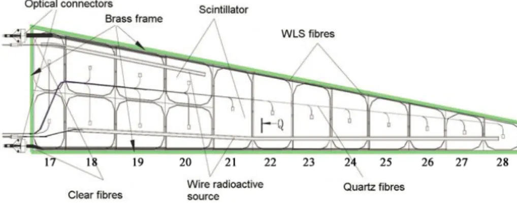
The HE is part of the CMS detector [15] at CERN’s Large Hadron Collider (LHC). It is a sampling calorimeter that uses brass as its passive material and scintillating tiles as its active material. It has 18 layers of active material, denoted layers 0 through 17, over most of its rapidity coverage. The zeroth layer of scintillator uses BC-408, a PVT-based scintillator from the Bicron division of the Saint Gobain corporation,1while the other layers use SCSN-81, a PS-based scintillator from
Kuraray.2 Figure1shows a schematic of the HE calorimeter.
The tiles are trapezoidal in shape. They contain a sigma groove that holds a 0.94 mm Y-11 (Kuraray) WLS fiber, mirrored on one end. Figure2 shows a schematic of the tiles, arranged in a “mega tile” that holds individual tiles. The calorimeter spans the pseudorapidity region from 1.305 to 3. The tiles are labeled by their pseudorapidity by “tower number”, starting with 16 for the ones at lowest pseudorapidity and going to 29. Due to the geometry of the detector, layers 0 through 4 contain tiles corresponding to towers 17 through 29. Layers 5 through 17 do not have tower 29. Only Layers 5 through 10 contain tower 16, and layers 14 through 17 do not have tile 17 as well. The megatiles are inserted into the brass absorber of the HE. The tile thickness is 0.9 cm in layer 0 and 0.37 cm in the rest of the layers. The sizes range from roughly 10 cm × 10 cm to about 20 cm × 20 cm. Clear fibers carry the light to hybrid photodiodes (HPD) [16], and each HPD signal is digitized by a Charge Integrator and Encoder (QIE) [17].
The light output of the tiles was measured during the 2012 8 TeV run of the LHC. The total delivered integrated luminosity was 23.3 fb−1, and was estimated as described in [18]. The time was estimated three different ways: using LHC 2012 run performancy summaries that included information on total delivered luminosity and hours in stable beam, using detailed CMS Web Based Monitoring records for each fill parameter including delivered luminosity and time in fill, and using the peak luminosity, luminosity lifetime, and fill length values to correlate average lumi rate with peak lumi. All three methods delivered very similar results. The instantaneous luminosity was fairly constant during the run.
The light was measured using a laser calibration system, consisting of a triggerable nitrogen laser, a system of neutral density filters, and a light distribution system that delivers the UV light to the scintillator tiles in layers 1 and 7 via quartz fibers. Light was also injected directly into the HPDs. The laser light was injected during the run at times without collisions, between fills of the accelerator with protons.
1Saint-Gobain Crystals, Courbevoie, France.
2Kuraray Corporation, Otemachi, Chiyoda-ku, Tokyo, 100-8115 Japan.
2016 JINST 11 T10004
Figure 1. Schematic of the CMS hadron endcap calorimeter.
Figure 2. Schematic of the CMS hadron endcap calorimeter scintillator megatiles tiles for tiles in layer 11
through 13. The numbers below the tiles represent the tower number. The megatiles in layers 0 through 4 have an additional tower at large η (tower 29). The megatiles in layers 5 through 10 contain tile 16 at low η. Layers 14 through 17 do not have tile 17.
2016 JINST 11 T10004
Plots of the light output relative to the initial light output as a function of the accumulatedintegrated luminosity during the run are shown in figure 3. They show an exponential decrease in light output with integrated luminosity. After the end of the run, a few percent recovery was observed for the tiles with the largest damage. The data are not corrected for this effect.
Cross checks of the results from the laser calibration from calculations of the jet energy scale, a calibration using a60Co source after the end of the run, and a measurement looking at the energy distribution in the towers using data taken with a single electron trigger as a function of integrated luminosity give similar albeit less precise results.
1000 101 0.1 0.2 0.3 0.4 0.5 0.6 0.7 0.8 0.9 1
Delivered Int. Luminosity, fb−1
Response degradation in HCAL Endcap
Layer 1 Response=exp(−Lumi[fb−1]/D) CMS 8 TeV data, 2012 η=1.99, D= 270fb−1 η=2.11, D= 206fb−1 η=2.25, D= 172fb−1 η=2.41, D= 123fb−1 η=2.58, D= 111fb−1 η=2.76, D= 65fb−1 (a)Layer 1. 1000 101 0.1 0.2 0.3 0.4 0.5 0.6 0.7 0.8 0.9 1
Delivered Int. Luminosity, fb−1
Response degradation in HCAL Endcap
Layer 7 Response=exp(−Lumi[fb−1]/D) CMS 8 TeV data, 2012 η=1.99, D= 651fb−1 η=2.11, D= 573fb−1 η=2.25, D= 446fb−1 η=2.41, D= 346fb−1 η=2.58, D= 281fb−1 η=2.83, D= 108fb−1 (b)Layer 7.
Figure 3. Ratio of light output to initial light output for tiles as a function of integrated luminosity, with
extracted dose constant, for CMS hadron endcap calorimeter scintillators in Layer 1 (a) and in Layer 7 (b).
To convert the exponential constant in terms of integrated luminosity to an exponential constant in terms of dose, the dose received by the tile per unit integrated luminosity is needed. Predictions of the absorbed dose in HE scintillator layers were obtained using the Monte Carlo code FLUKA 2011.2c [19, 20]. The FLUKA predictions for collisions use a model that represents the HE in detail, with brass, Dural (Aluminium, Cu, Mg, and Mn), Tyvek, air, and scintillator layers. The absorber regions are represented as 80 mm thick brass ‘LK75’ layers (with the exception of the last which is < 20 mm), with a density of 8.4 g/cm3and a fractional mass composition as follows: Cu 75%, Zn 24.533%, Si 0.3%, P 0.01%, Fe 0.1%, Sb, 0.005%, Pb 0.05%, Bi 0.002%. Layer 0 is a 10 mm thick polyvinyltoluene layer modelled with a density 1.032 g/cm3 and fractional mass composition: H 8.5292% and C 91.4708%. Other scintillator regions (layers 1–17) are 4 mm thick and represented with a polystyrene plastic scintillator of density 1.05 g/cm3 and fractional mass composition H 7.7423% and C 92.2577%. Since the energy loss per mass per unit area is more than a factor two higher for hydrogen than for most other materials, the spatial resolution used in the calculation was defined so that the dose estimates were not averaged over regions containing materials other than scintillator layers. For towers 28 and 29, the amount of material in front of the HE varies with azimuthal angle due, primarily, to to the rectangular shape of the crystals in the electromagnetic calorimeter. This irregularity is not yet simulated, and the dose is calculated for the average instead. The dose was calculated using an R-Phi-Z mesh, independent of the geometry,
2016 JINST 11 T10004
overlaying the HE region. The resolution was selected assuming a phi symmetry and aligned inorder to obtain dose values within the scintillator regions only. For the HE there was one phi bin in total, a one mm resolution in Z, and a one cm resolution in R. Predictions for the 4-TeV-per-beam ‘2012’ run use a “Run1” CMS FLUKA model, with a central beam pipe and muon endcap region which is modelled to reflect the configuration at that time.
Since the dose received varies over the surface of the tile, the rapidity-averaged value is used. Using a value averaged over the radius of the tile gives similar results. For layer 1, the dose received by a tile ranged from 0.01 to 0.2 Mrad. For layer 7, the dose received ranged from 0.00005 to 0.03 Mrad.
The doses and dose rates are highest for the tiles closest to the beam line. If the exponential constant D does not depend on dose rate, we would expect the tiles to have the same exponential con-stant, regardless of dose. Monte Carlo studies based on the optical transport code in GEANT4 [21] shows that the exponential constant does not depend strongly on the tile size. Measurements confirm the results of the simulation. Prior to LHC turn on, tiles constructed of SCSN-81 with dimensions of 5 cm × 8 cm, 12 cm × 8 cm, and 20 cm × 20 cm were irradiated at a 60Co source at Argonne National Laboratory at a relatively high dose rate of 100 krad/hr. The resulting dose constants were 1.9, 1.4, and 0.9 Mrad, respectively. The variation with size is much smaller than that seen with the in situ measurements [22]. The extracted dose constants are not corrected for this effect.
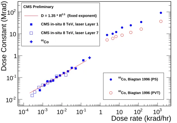
The extracted exponential constant in Mrad is shown in figure 4. The different points, at different dose rates, correspond to different tiles in layers 1 and 7. We see a strong dependence on dose rate, with the tiles with the lowest dose rate having the lowest exponential constant and thus suffering more damage for the same dose than the tiles with higher exponential constants.
We fit the extracted D values from the laser results to a power law with an exponent of 0.5. The results of the fit are included in figure4. The agreement is good.
3 Results from a low dose rate irradiation at a60Co source
A rectangular tile with WLS fiber, whose construction was similar to those used in the HE (SCSN-81, and with dimensions of 10 cm by 10 cm, with a 50 cm long mirrored fiber) was irradiated in air using the Michigan Memorial Phoenix 60Co source at the University of Michigan, Ann Arbor, MI. The integrated dose was 300 ± 30 krad accumulated over an irradiation time of 1080 hours, for a dose rate of 0.28 krad/hr. The light output when the tile is exposed to a (different) 60Co source was measured before and after irradiation using a Hamamatsu R580-17 PMT coupled to a Keithley picoammeter. An unirradiated identical tile was used to check the stability of the measurement system. The tile was allowed to recover for 6 days between the exposure and the “after” measurement, so as to measure only the permanent damage.
The resulting exponential constant is shown in figure4. The dose rate for this measurement was larger than that for any tile in the in situ measurement, and the resulting exponential constant is larger than that obtained from the in situ measurements but much smaller than values obtained from high dose rate reactor exposures discussed in the next section. Its value agrees well with the extrapolation of the trend from the in situ measurements to its dose rate.
2016 JINST 11 T10004
4 Comparison to previous results
We compare our results to those from ref. [2]. The authors studied both SCSN-81, which is PS-based, and Bicron-499-35, which is PVT-based. They irradiated disks with a 0.4 cm thickness and a 100 diameter with a gamma source. The light output was measured using an alpha source, after allowing time for recovery of the temporary damage. The exponential constant D was obtained, for dose rates below 14 krad/hr, where measurements were made for only one dose value, by reading the values of their data from their graphs of light output, and using eq. (1.1) to solve for D. For higher dose rates, where measurements were made for multiple values of the total dose d, the values of the light output versus dose rate are obtained from the functional form in their table 1. Values with the same dose rate but different dose are then fit with an exponential to obtain D.
The values from ref. [2] have exponential dose constants of tens of Mrad at high dose rate, much higher than the values of a few hundredths of a Mrad at the low dose rates probed in the HE. However, even though the geometry and construction of the scintillators studied in the in situ measurement and the measurements in ref. [2] are quite different, and the dose rates quite different, the functional dependence is similar.
Dose rate (krad/hr)
-4
10
10
-310
-210
-11
10
10
210
3Dose Constant (Mrad)
-2
10
-110
1
10
210
CMS Preliminary (fixed exponent) 0.5 D = 1.35 * RCMS in-situ 8 TeV, laser Layer 1 CMS in-situ 8 TeV, laser Layer 7
Co 60 Co, Biagtan 1996 (PS) 60 Co, Biagtan 1996 (PVT) 60
Figure 4. Exponential constant as a function of dose rate. Results from scintillators based on PS are shown
in blue, while those based on PVT are shown in red. Results from Layer 1 (7) of the CMS HE scintillator are indicated by filled squares (open squares). Each point corresponds to a different tile pseudorapidity. Results from the60Co irradiations discussed in Biagtan [2] are indicated with circles. The label “60Co, CMS” (cross)
refers to the measurement first presented in this paper, which was taken using irradiation from a gamma source. A fit to the in situ data to a power law is shown, where the power is set to 0.5.
2016 JINST 11 T10004
5 Conclusions
We have looked at the dependence of the light loss for scintillator tiles installed in the CMS endcap hadron calorimeter as a function of both dose and dose rate. We see a power law dependence consistent with that predicted by diffusion of oxygen (or other gas) into the scintillator. We see the functional form is in reasonable agreement with results from gamma source irradiations both by us and by the authors of ref. [2].
Acknowledgments
We would like to thank the CMS BRIL group for doing the FLUKA calculation and the staffs at the Michigan Memorial Phoenix source and the Argonne source for their help. We congratulate our colleagues in the CERN accelerator departments for the excellent performance of the LHC and thank the technical and administrative staffs at CERN and at other CMS institutes for their contributions to the success of the CMS effort. In addition, we gratefully acknowledge the computing centres and personnel of the Worldwide LHC Computing Grid for delivering so effectively the computing infrastructure essential to our analyses. Finally, we acknowledge the enduring support for the construction and operation of the LHC and the CMS detector provided by the following funding agencies: BMWFW and FWF (Austria); FNRS and FWO (Belgium); CNPq, CAPES, FAPERJ, and FAPESP (Brazil); MES (Bulgaria); CERN; CAS, MoST, and NSFC (China); COLCIENCIAS (Colombia); MSES and CSF (Croatia); RPF (Cyprus); SENESCYT (Ecuador); MoER, ERC IUT and ERDF (Estonia); Academy of Finland, MEC, and HIP (Finland); CEA and CNRS/IN2P3 (France); BMBF, DFG, and HGF (Germany); GSRT (Greece); OTKA and NIH (Hungary); DAE and DST (India); IPM (Iran); SFI (Ireland); INFN (Italy); MSIP and NRF (Republic of Korea); LAS (Lithuania); MOE and UM (Malaysia); BUAP, CINVESTAV, CONACYT, LNS, SEP, and UASLP-FAI (Mexico); MBIE (New Zealand); PAEC (Pakistan); MSHE and NSC (Poland); FCT (Portugal); JINR (Dubna); MON, RosAtom, RAS and RFBR (Russia); MESTD (Serbia); SEIDI and CPAN (Spain); Swiss Funding Agencies (Switzerland); MST (Taipei); ThEPCenter, IPST, STAR and NSTDA (Thailand); TUBITAK and TAEK (Turkey); NASU and SFFR (Ukraine); STFC (United Kingdom); DOE and NSF (U.S.A.).
References
[1] C. Zorn, Plastic and liquid organic scintillators, in Instrumentation in High Energy Physics, 2nd Edition, F. Sauli ed.,World Scientific(1993), chapter 4, pp. 218–279.
[2] E. Biagtan, E. Goldberg, R. Stephens, E. Valeroso and J. Harmon, Gamma dose and dose rate effects
on scintillator light output,Nucl. Instrum. Meth. B 108(1996) 125.
[3] U. Holm and K. Wick, Radiation Stability of Plastic Scintillators and Wave Length Shifters,IEEE Trans. Nucl. Sci. 36(1989) 579.
[4] K. Wick, D. Paul, P. Schröder, V. Stieber and B. Bicken, Recovery and dose rate dependence of
radiation damage in scintillators, wavelength shifters and light guides,Nucl. Instrum. Meth. B 61
(1991) 472.
[5] B. Bicken, U. Holm, T. Marckmann, K. Wick and M. Rohde, Recovery and permanent radiation
damage of plastic scintillators at different dose rates,IEEE Trans. Nucl. Sci. 38(1991) 188.
2016 JINST 11 T10004
[6] B. Bicken, A. Dannemann, U. Holm, T. Neumann and K. Wick, Influence of temperature treatment on
radiation stability of plastic scintillator and wavelength shifter,IEEE Trans. Nucl. Sci. 39(1992)
1212.
[7] A.D. Bross and A. Pla-Dalmau, Radiation damage of plastic scintillators,IEEE Trans. Nucl. Sci. 39 (1992) 1199.
[8] N. Giokaris, M. Contreras, A. Pla-Dalmau, J. Zimmerman and K.F. Johnson, Study of dose-rate effects on the radiation damage of polymer-based SCSN23, SCSN81, SCSN81+Y7, SCSN81+Y8 and
3HF scintillators,Radiat. Phys. Chem. 41(1993) 315.
[9] CMS collaboration, The CMS hadron calorimeter project: Technical Design Report, CERN-LHCC-97-031(1997) [CMS-TDR-2].
[10] T. Förster, Zwischenmolekulare energiewanderung und fluoreszenz,Ann. Phys. 437(1947) 55.
[11] T. Seguchi, S. Hashimoto, K. Arakawa, N. Hayakawa, W. Kawakami and I. Kuriyama, Radiation induced oxidative degradation of polymers — I: Oxidation region in polymer films irradiated in
oxygen under pressure,Radiat. Phys. Chem. 17(1981) 195.
[12] W. Busjan, K. Wick and T. Zoufal, Shortlived absorption centers in plastic scintillators and their
influence on the fluorescence light yield,Nucl. Instrum. Meth. B 152(1999) 89.
[13] P.C. Trimmer, J.B. Schlenoff and K.F. Johnson, Spatially resolved uv-vis characterization of
radiation-induced color centers in poly(styrene) and poly(vinyltoluene),Radiat. Phys. Chem. 41
(1993) 57.
[14] N. Emanuel and A. Buchachenko, Chemical Physics of Polymer Degradation and Stabilization, VNU Science Press (1987).
[15] CMS collaboration, The CMS experiment at the CERN LHC,2008 JINST 3 S08004.
[16] P. Cushman, A. Heering and A. Ronzhin, Custom HPD readout for the CMS HCAL,Nucl. Instrum. Meth. A 442(2000) 289.
[17] T. Shaw et al., Front end readout electronics for the cms hadron calorimeter,IEEE Nucl. Sci. Symp. Conf. Rec. 1(2002) 194.
[18] CMS collaboration, Absolute Calibration of the Luminosity Measurement at CMS: Winter 2012
Update,CMS-PAS-SMP-12-008(2012).
[19] A. Ferrari, P.R. Sala, A. Fasso and J. Ranft, FLUKA: A multi-particle transport code (program
version 2005),CERN-2005-010(2005) [INFN-TC-2005-11] [SLAC-R-773].
[20] T.T. Bohlen et al., The fluka code: Developments and challenges for high energy and medical
applications, Nucl. Data Sheets 120 (2014) 211.
[21] GEANT4 collaboration, S. Agostinelli et al., GEANT4: A Simulation toolkit,Nucl. Instrum. Meth. A 506(2003) 250.
[22] P. De Barbaro, CMS IN-2008/022, private communication.