Proceedings of the 36thEuropeanMicrowave Conference
Observation of
Negative Refraction and Negative Phase Velocity
in
True Left-Handed Metamaterials
1 ~~~~~2
Ekmel
Ozbay'and Costas
M.
Soukoulis
'Department of
Physics, Department of Electrical and Electronics Engineering, Nanotechnology Research
Center,
Bilkent
University, Bilkent,
06800
Ankara,
Turkey
2Institute
of Electronic
Structure and
Laser, Foundation for Research and
Technology,
Hellas &
Dept.
of
Materials Science and Technology, University of Crete, Greece
Abstract - We reportatrueleft-handed (LH) behavior ina composite metamaterial consisting of periodically arranged split ring resonator (SRR) and wire structures. The magnetic resonance of the SRR structure is demonstrated by comparing the transmission spectra of SRRs with that of closed SRRs. We confirmed experimentally that the effective plasma frequency of the LHmaterial composed of SRRs and wires is lower than the plasma frequency of the wires. A well-defined left-handed transmission band with apeak value of -1.2 dB(40.3 dB/cm) is obtained. We also report the transmission characteristics ofa2D
composite metamaterial (CMM) structure infree space. At the frequencies where left-handed transmission takes place, we
experimentally confirmed that the CMMstructure has effective negative refractive index. Phase shift between consecutive numbers of layers of CMM is measured and phase velocity is showntobenegativeatthe relevantfrequencyrange.Refractive index values obtained from the refraction experiments and the phase measurements are in good agreement. The experimental results agreeextremely well with the theoretical calculations.
Index Terms - Left-handed medium, metamaterial, negative
phase velocity, negativerefraction, split ringresonator. I. INTRODUCTION
Veselago predicted that a medium with negative permittivity, £, and negative permeability,
t,
will exhibit negative indices of refraction [1]. When both the permittivity and the permeability are negative the electric field, the magnetic field and the wavevector components form a left-handed coordinate system, hence the name left-handed material (LHM) is used for description. Such a medium isexpected to exhibit unusual physical properties such as negative refraction, reversal of Doppler shift, backward Cherenkov radiation. A medium with £ < 0 can easily be realized, e.g. by periodically arranged metallic wires [2]. On the other hand, the
R(co)
< 0 was a challenge due to lack ofmagnetic charge .Pendryet. alsuggestedthataperiodicarray of metallic split ringresonator (SRR) structures exhibit
R(co)
< 0 close to magnetic resonance frequency
cop
[3]. Thisproposal brought the possibility of observing left-handed medium in to reality. Recently, this idea is brought to
experimental investigation by constructing a composite
metamaterial (CMM) consisting of two components which have £(co) < 0, a periodically arranged wire medium, and
R(CO)
< 0, a periodically arranged SRR medium,simultaneously over a certain frequency range, respectively [4],[5]. Various studies employing different structure designs extended this investigation [4]-[8]. Negative refraction of electromagnetic waves at the interface of CMMs is also observed [9]-[11] which supported the existence ofa LHM. The parameters £ and
[t
can be obtained by a retrieval procedure from the numerically calculated transmission and reflection data for finite size CMMs [12]-[14], under the assumption of a homogeneous medium. This procedure confirmed [15],[16] that a medium composed of SRRs and wirescanindeed be characterizedbyeffective£and[t.
A medium transmits electromagnetic waves when both £ and
[t
have the same sign, i.e., bothare negative orboth are positive. If they have opposite signs the medium effectivelyreflects theincoming electromagneticwave. The existence of apass band for the CMM within therespective stopbands of SRR-only and wire-only mediums isintuitivelyconsideredas evidence for LH behavior. We experimentally demonstrate that the dielectric response of the CMM differs substantially
from that of the wire-onlymedium, by measuring cop for the CMM andwire-onlystructures. Itis evident thatashift in the plasma frequency renders the aforementioned intuitive
approach inapplicable. This is a new feature that was not recognized in previous work. Based on this observation we present a newCMM structurewhich exhibitstrueleft-handed behavior and has atransmission band with apeak value at
-1.2 dB. To our knowledge, this is the highest transmission valuereportedforaLHM.
II.TRUE LEFT-HANDEDCOMPOSITEMETAMATERIALS In general, a SRR structure exhibits both magnetic
response [3] induced by the solenoidal currents flowing
around the SRR, and electric response [17], [18] by the
dipole-like charge distribution along the incident electric field. The magnetic response of the SRR structure exhibits a
resonance in the transmission spectrum. This resonance behavior is observedas adip inthe transmissionspectrumof asingleSRRstructure. When SRRsarearrangedinaperiodic medium, due to the interaction between SRRs the resulting
September 2006,ManchesterUK
959
medium exhibits aband gapin the transmissionspectrum. A bandgap in the transmission spectrum of periodic SRR mediummaybe duetonegative£ ornegative tor solely due totheperiodicity. This ambiguity canbe resolved by using a structure in which the splits in the ring resonators areclosed (CSRR). This will destroy the magnetic resonance but still keep the electric resonance. A gap presentin SRRbut notin CSRRwill thencorrespondtop<0.
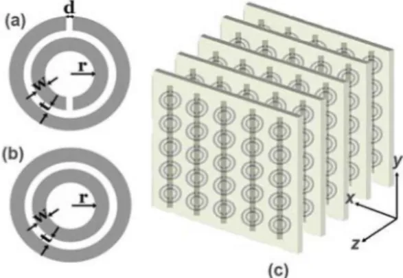
Fig. 1. (a) split ring resonator (SRR) (b) ring resonator with splits closed (CSRR) (c) Periodic CMM composedof SRRs on one side,
wires on the other side of dielectric boards.
We fabricated SRR (Fig. l.a) and CSRR (Fig. l.b) structuresby using standard printed circuit board technology. Themeasurementsetupconsists ofHP 851OC vectornetwork
analyzer and standardgainhornantennas fortransmittingand receiving electromagnetic waves. The incident field propagates along thexdirection withE, andH, alongyandz
directions,
respectively.The measured transmission spectrum for SRR (solid line) medium and the CSRR (dashed line) medium are shown in Fig. 2. The first band gap (3.55-4.05 GHz) of the SRR medium isnotpresentinthe CSRRmedium, indicating t<0. Note that the second band gap, 8.1-11.9 GHz, is observed both in the transmission spectrum of the SRR and CSRR mediums. This measurement clearly shows that the stop bands ofan SRR medium can notbe automaticallyattributed to "negative p" behavior. Some of the observed gaps could also originate from the electrical response of the SRRs or from Bragggapsduetoperiodicity.
_0 g_ 40 E 3Ow
§
40-5 A 4 6 8 10 12 14 Frequency(GHz)Fig.2. Measured transmission spectra of aperiodic SRR medium
(solid)andperiodicCSRR medium(dashed)between 3-14 GHz.
-60-20 u
-40
3 4 5 6 7 8 9
Frequency (GHz)
Fig. 3. Measured transmission spectra of wires (dashed line) and closed CMM (solid line) composed by arranging closed SRRs and wiresperiodically.
Anotherpointtobe discussed is the electricresponseof the CMM. Previously reported transmission results did not emphasize the interaction between SRR and wire structures. However, it was recently found [17] that the SRRs, in additionto theirresonant magnetic response at
W),
exhibit a resonant electric response atw0.
The behavior is similar to that of a periodic cut-wire medium (wires of finite length) which exhibits a stop band with a well-defined lower edge due to the discontinuous wire geometry [8]. As aresult, the SRRs contribute to the effective permittivity of the CMM, causing a downward shift on the plasma frequency determined solely from wire structures [17]. To demonstrate thiseffect,aCMMconsisting of periodic alternating layers of CSRRs and wires is used(Fig. lc). Thickness, length and the width of the wires are 30 ptm, 13.5 cm and 0.9 mm respectively. Fig. 3 displays the measured transmission spectraof wire only medium and CMMconsisting of CSRR and wire layers. The cop of the wire-only structure around 8 GHz, is reduced down to 5.3 GHz within the closed CMM structure. AsseeninFig. 3,cop of the CMM is lower than that of the wire-only medium alone. It is crucial to determine whether the shift in plasma cut-off frequency covers the magnetic resonancegap, which would render the CMM as a right-handed medium.The experimental data presented in Fig. 3 clearly shows that one needs to take the shift in the plasma into account when designing mediums for LH behavior. To observe true LH behavior we designed the SRRs such that the first
bandgap of SRR structure between 3.55 - 4.05 GHz is not obscured by the shift in plasma frequency. The CMM structureis made ofNx= 5,
Ny
= 15, andN = 24unit cells.Each unit cell has a single SRR, and a copper wire from stacked SRR and wirelayers,with latticespacing
a,
=ay=
8.8mm, a
z=
6.5 mm. The transmission spectra for SRR only(solid line), wire only (dashed line) and CMM (bold solid line) periodic structures are displayed in Fig. 4. The simulationsagree verywell with theexperimentaldata.
The CMM structure allows propagation of EM waves between 3.6 and 4.1 GHz, where both £ and t are negative.
The CMM passband exactly coincides with thestopband of SRR. The transmissionpeakat3.9 GHz is -1.2dB, which isa significantly highvalue foramaterial made of metals.
.-I 0 U) E U E_ Frequency
(GHz)
,-. 7 Frequency(GHz)Fig. 4. Comparison of the measured transmission spectra of SRR (dashed), wire (dotted) and CMM solid line.
Similarly,the simulations predict a transmission peak at 3.92 GHz of -1.5 dB.We stressthat, asimilar transmission band is not present fora CMM composed ofCSRRs and wires (Fig. 3). The electric response contribution of SRRs is also evident here: If the wpof the wire-only structure (dashed line in Fig. 4) were used to identify the £ < 0regime for the CMM, the transmission between 5.3 - 8 GHz would have occured in a
regime with£ < 0andR>0,which isnotpossible. However, as Fig. 3 suggests, the£ >0 regime of the combined electric responseof SRRs and wiresstart at5.3 GHz.
The transmitted phase of CMMs is measuredtoinvestigate the phase velocity within both the left-handed (3.73-4.05 GHz) and right-handed (5.4-7.0 GHz) transmission bands. Phase measurements are performed on rectangular slabs of CMMs, with various numbers of layers. Fig. 5 shows the transmitted phase of CMMs (with varying number of layers) between frequencies 5.4-7.0 GHz, where CMM acts as a right-handed medium. As shown in Fig. 5, the phase of the transmittedEM waveincreases, whenalonger CMM is used, which is a typical right-handed behavior. On the other hand, increasing the number of layers decreases the phase of the transmitted EM wave at the left-handed frequency region (Fig. 6). As shown in the inset of Fig. 6, the average phase shift is negative for the relevant frequency range, which indicates that thephase velocity is negative.
20 < e15 0.'1 5.5 6 6.5 7 Frequency (GHz)
Fig.5. Unwrapped transmission phase data obtained from different lengths of CMM between 5.4 - 7.0 GHz, where
right-handed transmission peak takes place. Inset: Average phase difference between consecutive numbers oflayers of CMM. Phase shift ispositivebetween 5.4-7.0 GHz.
Fig. 6. Unwrapped transmission phase data obtained from different lengths of CMM between 3.73 - 4.05 GHz, where left-handed transmission peak takes place. Inset: Average phase difference between consecutive numbers oflayers of CMM. Phase shift isnegative between 3.73-4.05 GHz.
III. NEGATIVE REFRACTION
Up to this point we concentrated on the transmission properties of metamaterial mediums consisting of SRR and wire structures. Wedemonstrated thata suitable combination of wires and SRRs exhibittrueleft-handed transmission peak inthe transmission spectrum. Two veryinteresting properties of the LH medium are the negative refraction and the negative phase velocities. To investigate the negative refraction and negative phase velocities we studied the refraction and transmission phase properties of a 2 dimensional CMM medium.
The 2D CMM medium is fabricated by standard printed circuit board technology. The SRR and wire patterns are fabricated onthe front and back sides ofFR4 circuit boards which have 30 ptmthickdepositedcopperlayer. The incident electromagnetic (EM) wavepropagates along thex direction, whileEisalongydirection, andHisalongzdirection.
i.
0u
4 5 6
Frequency(GHz)
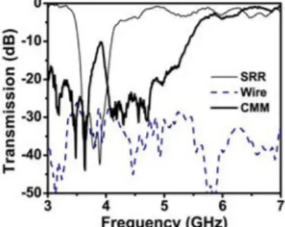
Fig. 7. Measured transmission spectraofaperiodic SRR medium
(solid line), periodic wire medium (dashed line) and 2D CMM medium(bold solid line) between 3-7 GHz.
Fig. 7 shows the measured transmissionspectraofperiodic SRRs (solid line) and wires (dashed line) and 2D CMM between 3-7 GHz. The bandgap of SRR between 3.55-4.05 GHz is dueto magnetic resonanceofperiodic SRR medium,
hence
R(co)
< 0 for this frequency range. The 2D CMM structure allows propagation ofEM waves between 3.7 and961 - 5Layer *-- 6Layer 7Layer ..- 8Layer - 9Layr 2 3 SRR Mm cmm 0., N F, 4w i f% 1, I .i %1. p I I 4 t I i. 4 I t, .-Jo. la.... c 040 0 0
I
40-0 c j!40.4.1 GHz, where both £and ,u are negative. The CMM pass band coincides with the stop band of SRR. The transmission peak at 3.92 GHz is -10.2 dB, which is significantly higher than the previously reported 2D CMM structures [5],[10].
The transmission band starting from 5.3 GHz is due to downward plasma frequency shift, since the £ >0 regime of the combined electric response of SRRs and wires starts at 5.3 GHz.
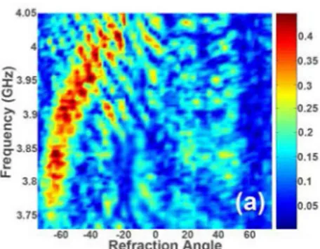
We constructed aprism shaped2D CMM structure (witha wedge angleof 0 =260) fornegative refraction. Fig. 8 shows the transmission spectrum as a function of frequency and refraction angle. The transmitted EM waves are refracted towards the negative side of the surface normal within the frequency range of 3.73 - 4.05 GHz. At lower frequencies
the EM waves are refracted at higher negative refraction angles, which results in a higher negative refractive index. On the other hand the refraction index is lowered with increasing frequencies. By employing Snell's law (nCMM
sinOi
= nair
sinOr)
an effective refractive index can be defined forthe CMM.
Atf=
3.92 GHz, the incidenceangle is0i
= 26°, and EM wave is refractedat an angle of0r
= 550, then from Snell's lawweobtainneff=-1.87+0.05at3.92 GHz.Fig. 8. Transmission spectra as a function
refractionangle. of frequency and
IV.CONCLUSION
Inconclusion, wehavesuccessfully demonstratedtrue left-handed behavior in free space withahigh transmission peak. The left-handed transmission band exactly coincides with the region where both dielectric permittivity and magnetic
permeability take negative values. In addition, we have successfully demonstrated a left-handed transmission band for2D CMMstructureinfreespace withahightransmission
peak. We experimentally confirmed that 2D CMM has negative refractive index at the entire left-handed frequency range (3.73-4.05 GHz). Phase shift and therefore phase velocity is shown to be negative, and the values ofnegative
refractive indices obtained from the refraction experiments and thephasemeasurements areingoodagreement.
ACKNOWLEDGEMENT
This work is supported by EU-DALHM, EU-METAMORPHOSE, EU-PHOREMOST.
REFERENCES
[1] V.G. Veselago, "The electrodynamics of substances with simultaneously negative values of permittivity and permeability," Sov. Phys. USPEKHI, vol. 10, p.509,1968. [2] J.B. Pendry, A.J. Holden, D.J. Robbins, and W.J. Stewart,
"Low frequency plasmons in thin-wire structures," Journal of Physics: Condensed Matter, vol. 10, p. 4785, 1998.
[3] J.B. Pendry, A.J. Holden, D.J. Robbins, and W.J. Stewart, "Magnetism from conductors and enhanced nonlinear phenomena," IEEE Trans. Microw. Th. Tech., vol. 47, p. 2075,
1999.
[4] D.R. Smith, W.J. Padilla, D.C.Vier, S.C. Nemat-Nasser, and S. Schultz, "Composite medium with simultaneously negative permeability and permittivity," Phys. Rev. Lett., vol. 84, p. 4184, 2000.
[5] S. Linden, C. Enkrich, M. Wegener, J.F. Zhou, T. Koschny, and C.M. Soukoulis, "Magnetic response of metamaterials at 100 terahertz," Science, vol.306, p. 1351,2004.
[6] M. Bayindir, K. Aydin, E. Ozbay, P. Markos, and C.M. Soukoulis, "Transmission properties ofcompositemetamaterial infree space," Appl. Phys. Lett., vol.81, p. 120, 2002.
[7] N. Fang, H. Lee, C. Sun, and X. Zhang, "Sub-diffraction-limited optical imaging with a silver superlens," Science, vol. 308, p.534,2005.
[8] E. Ozbay, K. Aydin, E. Cubukcu, and M. Bayindir,
"Transmission and ReflectionProperties of Composite Double Negative Metamaterials in FreeSpace,"IEEETrans.Antennas Propag.,vol.51, p. 2592, 2003.
[9] I. Bulu, H. Caglayan, and E. Ozbay, "Experimental demonstration of subwavelength focusing of electromagnetic
waves by labyrinth-based two-dimensional metamaterials,"
Optics Letters, vol.31, p. 814, 2006.
[10] C.G. Parazzoli, R.B. Greegor, K.Li, B.E.C. Koltenbah, and M. Tanielian, "Experimental Verification and Simulation of
Negative Index of Refraction Using Snell's Law," Phys. Rev. Lett.,vol.90, p. 107401, 2003.
[11] A.A. Houck, J.B. Brock, and I.L. Chuang, "Experimental Observations of a Left-Handed Material That Obeys Snell's Law," Phys. Rev. Lett., vol. 90, p. 137401, 2003.
[12] M. Kafesaki, T. Koschny, R. S. Penciu, T.F. Gundogdu, E.N. Economou, and C.M. Soukoulis, "Left-handed metamaterials: detailed numerical studies of the transmissionproperties,"J. of
Optics A: Pure andAppliedOptics,vol.7,p.S12,2005. [13] P. Markos and C.M. Soukoulis, "Transmission properties and
effective electromagnetic parameters of double negative
metamaterials," OpticsExpress, vol. 11, 649(2003).
[14] T.Koschny, P. Markos, E.N. Economou, D.R.Smith,and C.M.
Soukoulis, "Impact of inherentperiodic structure on effective medium description of left-handed and relatedmetamaterials,"
Physical Review B, vol. 71, p.245105,2005.
[15] D.R. Smith and S. Schultz, P. Markos and C.M. Soukoulis,
"Determination of effective permittivity and permeability of metamaterials from reflection and transmission coefficients,"
Phys. Rev. B, vol.65,p. 195104,2002.
[16] T. Koschny, P. Markos, D.R. Smith, and C.M. Soukoulis,
"Resonant and antiresonant frequency dependence of the effective parameters ofmetamaterials," Phys. Rev. E, vol. 68,
p.065602(R),2003.
[17] T. Koschny, M. Kafesaki, E.N. Economou, and C.M.
Soukoulis,"Effective mediumtheoryof left-handedmaterials," Phys.Rev.Lett.,vol.93,p. 107402,2004.
[18] K.Aydin, K.Guven, LeiZhang,M.Kafesaki, C.M.Soukoulis,
and E.Ozbay, "Experimental Observation of True Left-Handed Transmission Peak in Metamaterials," Optics Letters, vol. 29,
p.2623,2004.