MODELING, CONTROL AND
TECHNO-ECONOMIC ANALYSIS OF KARABUK
UNIVERSITY MICROGRID
2020
PhD THESIS
ELECTRICAL-ELECTRONICS ENGINEERING
NURI ALMARGANI ALI ALMAGRAHI
MODELING, CONTROL AND TECHNO-ECONOMIC ANALYSIS OF KARABUK UNIVERSITY MICROGRID
Nuri Almargani Ali ALMAGRAHI
T.C
Karabuk University Institute of Graduate Programs
Department of Electrical-Electronics Engineering Prepared as
PhD Thesis
Assoc. Prof. Dr. Ziyodulla YUSUPOV
KARABUK April 2020
ii
I certify that in my opinion the thesis submitted by Nuri Almargrani Ali ALMAGRAHI titled “MODELING, CONTROL AND TECHNO-ECONOMIC ANALYSIS OF KARABUK UNIVERSITY MICROGRID” is fully adequate in scope and in quality as a thesis for the degree of PhD.
Assoc. Prof. Dr. Ziyodulla YUSUPOV ... Thesis Advisor, Department of Electrical-Electronics Engineering
KABUL
This thesis is accepted by the examining committee with a unanimous vote in the Department of Electrical-Electronics Engineering as a PhD thesis. April 29, 2020
Examining Committee Members (Institutions) Signature
Chairman : Prof. Dr. Necmi S. TEZEL (KBU) ...
Member : Assoc. Prof. Dr. Ziyodulla YUSUPOV (KBU) ...
Member : Assoc. Prof. Dr. Selami SAĞIROĞLU (KBU) ...
Member : Assoc. Prof. Dr. Metin VARAN (SUBU) ...
Member : Assist. Prof. Dr. Adem DALCALI (BANU) ...
The degree of PhD by the thesis submitted is approved by the Administrative Board of the Institute of Graduate Programs, Karabuk University.
Prof. Dr. Hasan SOLMAZ ...
iii
“I declare that all the information within this thesis has been gathered and presented in accordance with academic regulations and ethical principles and I have according to the requirements of these regulations and principles cited all those which do not originate in this work as well.”
iv ABSTRACT
Ph.D. Thesis
MODELING, CONTROL AND TECHNO-ECONOMIC ANALYSIS OF KARABUK UNIVERSITY MICROGRID
Nuri Almargani Ali ALMAGRAHI
Karabuk University Institute of Graduate Programs
Department of Electrical-Electronics Engineering
Thesis Advisor:
Assoc. Prof. Dr. Ziyodulla YUSUPOV April 2020, 169 pages
Microgrid defines as collection of distributed energy resources and loads that operates as single system by providing power and heat. In last decades, the developing of power electronic is to provide the flexibility operation of power system integrated with microsources as a single aggregated system.
Variety sources of distributed generation and loads are a reason of high nonlinearities, changing dynamics, and uncertainties. For example, some renewable energy sources such as solar PV and wind turbines work under unpredictable environmental conditions and turbulent. To solve these issues, it requires to develop intelligent control strategies, and thereby to increase reliability and performance of power systems. And thus, microgrids performance strongly depend on the applied control strategies. Therefore, collaboration of microgrid and electric grid are required to provide reliability, security and stable operation of the power system. Based on these
v
considerations, in this work, the modeling and simulation of Karabuk university microgrid are developed, considered operation in both grid-connected and island modes. Microgrid control system is designed and developed to ensure the power balance between distributed energy sources and loads along with continues energy supply during fault conditions. Fault control of microgrid system is executed. The fault control and optimal power flow control has been implemented in the microgrid system to effectively manage the energy in the system.
Techno-economic and environmental analyses are executed using HOMER Grid software tool to evaluate the effectiveness of microgrid application at Karabuk university campus.
Key Words : Microgrid, distributed energy resources, optimization, fault control. Science Code : 90502
vi ÖZET
Doktora Tezi
KARABÜK ÜNİVERSİTESİ MİKRO ŞEBEKESİNİN MODELLENMESİ, KONTROLÜ VE TEKNO-EKONOMİK ANALİZİ
Nuri Almargani Ali ALMAGRAHI
Karabük Üniversitesi Lisansüstü Eğitim Enstitüsü
Elektrik-Elektronik Mühendisliği Anabilim Dalı
Tez Danışmanı:
Doç. Dr. Ziyodulla YUSUPOV Nisan 2020, 169 sayfa
Mikro şebeke, güç ve ısı sağlayarak tek bir sistem olarak çalışan dağıtılmış enerji kaynaklarının ve yüklerin toplanması olarak tanımlanmıştır. Son yıllarda güç elektroniğinin geliştirilmesi, güç sisteminin yenilenebilir enerji kaynaklarla esnek bir şekilde tek bir toplu sistem olarak çalışmasını sağlamaktadır.
Dağıtılmış üretim ve yüklerin çeşitli kaynakları, yüksek doğrusalsızlıkların, değişen dinamiklerin ve belirsizliklerin bir nedenidir. Örneğin, güneş PV ve rüzgâr türbinleri gibi bazı yenilenebilir enerji kaynakları, öngörülemeyen çevre koşulları ve türbülans altında çalışır. Bu sorunları çözmek için akıllı kontrol stratejileri geliştirmek ve böylece güç sistemlerinin güvenilirliğini ve performansını arttırmak gerekir. Mikro şebekelerin performansı büyük ölçüde uygulanan kontrol stratejilerine bağlıdır. Bu nedenle, güç sisteminin dayanaklığını, güvenliğini ve istikrarlı çalışmasını sağlamak için mikro şebeke ve elektrik şebekesinin uygun çalışması gerekmektedir. Bu
vii
düşüncelere dayanarak, bu çalışmada hem şebekeye bağlı hem de özerk tarzda çalışan Karabük Üniversitesi mikro şebekesinin modellenmesi ve simülasyonu geliştirilmiştir. Microgrid kontrol sistemi, dağıtılmış enerji kaynakları ve yükler arasındaki güç dengesini sağlamak ve arıza koşullarında devam eden enerji tedarikini sağlamak için tasarlanmış ve geliştirilmiştir. Mikro şebeke sisteminin arıza kontrolü yapılmıştır. Arıza kontrolü ve optimum güç akışı kontrolü, sistemdeki enerjiyi etkin bir şekilde yönetmek için mikro şebeke sistemine uygulanmıştır.
Karabük Üniversitesi'nde mikro şebeke uygulamasının etkinliğini değerlendirmek için HOMER Grid yazılımını kullanılarak teknolojik-ekonomik ve çevresel analizler yapılmıştır.
Anahtar Kelimeler : Mikro şebeke, dağıtılmış enerji kaynakları, optimizasyon, arıza kontrolü.
viii
ACKNOWLEDGMENT
After sincerely thanking Allah for all blessings and bounties.
First, I express to give thanks to my advisor, Assoc. Prof. Dr. Ziyodulla YUSUPOV, for his guidance and assistance in preparation of my dissertation thesis.
I would like also to acknowledge the assistance of many people who provided help, support, and encouragement, enabling me to complete my Ph.D. dissertation. In particular, I would like to extend my thanks to the Prof. Dr. Necmi Serkan TEZEL and Assoc. Prof. Dr. Selami SAĞIROĞLU for their support.
I wish to express my love to my wife, and my children for their love, support and encouragement.
I also would like to thank all my friends and colleagues who helped me in many other ways. I will not forget the special help and financial support provided to me by my government (Libya), which made it possible for me, and gave me the best chance, to attend this Ph.D. education program to equip me to be able to contribute the development of my country.
ix CONTENTS Page APPROVAL ... II ABSTRACT ... IV ÖZET... VI ACKNOWLEDGMENT ... VIII CONTENTS ... IX LIST OF FIGURES ... XIII LIST OF TABLES ... XVI SYMBOLS AND ABBREVITIONS INDEX ... XVII
PART 1 ... 1
INTRODUCTION ... 1
1.1. PROBLEM STATEMENT AND MOTIVATION OF THE THESIS ... 2
1.2. RESEARCH OBJECTIVES ... 3
1.3. METHODOLOGY ... 4
1.4. LITERATURE REVIEW... 6
PART 2 ... 12
MICROGRIDS ARCHITECTURE ... 12
2.2. MICROGRID OPERATION MODES ... 15
2.3. MICROGRID TYPES ... 20 2.3.1. DC Microgrid... 21 2.3.2. AC Microgrid... 22 2.3.2.1. Line-Frequency AC Microgrid ... 24 2.3.2.2. High-Frequency AC Microgrid ... 25 2.3.3. Hybrid Microgrid ... 27
2.4. STANDARDS FOR MICROGRIDS ... 28
x
Page
PART 3 ... 35
CONTROL STRATEGIES OF MICROGRID ... 35
3.1. PRIMARY CONTROL ... 37
3.1.1. Grid-feeding Controls ... 38
3.1.2. Grid-forming Control... 39
3.1.2.1. Control Methods With Communication Link ... 40
3.1.2.2. Control Methods Without Communication Link ... 41
3.2. SECONDARY CONTROL ... 47
3.2.1. Centralized Control ... 48
3.2.2. Decentralized Control ... 51
3.2.2.1. Distributed Secondary Control ... 53
3.2.2.2. Decentralized Secondary Control ... 56
3.3. TERTIARY CONTROL ... 56
3.3.1. Centralized Tertiary Control ... 57
3.3.2. Distributed Tertiary Control ... 58
PART 4 ... 59
MICROGRID MODELING AND DYNAMICS ... 59
4.1. STUDIED SYSTEM CHARACTERISTICS ... 60
4.2 CONNECTION MODELING BETWEEN THE MAIN GRID AND THE KBU MICROGRID ... 66
4.2.1. Modeling of the Medium Voltage Transmission Lines ... 66
4.2.2. Modeling of Medium Voltage Transmission Lines ... 68
4.2.3. Passive Load Modeling... 69
4.2.4. Modeling of Relevant Buses ... 70
4.2.5. Grid Bus ... 71
4.2.6. MV Bus ... 72
4.3. GRID-CONNECTED KBU MICROGRID ... 73
4.3.1. Microgrid Bus ... 73
4.3.2. Overall Microgrid Architecture ... 74
4.4. KBU MICROGRID ARCHITECTURE IN ISLANDED MODE ... 75
xi
Page
4.5.1. Modeling a Diesel Generator ... 77
4.5.2. PV Panels ... 82
4.5.3. Modeling MPPT with Boost Converter ... 85
4.5.4. Modeling of battery storage system ... 88
4.5.5. Modeling Voltage Source Inverter ... 90
4.5.6. Static Transfer Switch... 91
PART 5 ... 93
LOAD SHARING AND FAULT CONTROL OF MICROGRID SYSTEM ... 93
5.1. INTRODUCTION ... 93
5.2. MODELING AND SIMULATION OF KBU MICROGRID ... 94
5.3. MATLAB SIMULATIONS OF KBU MICROGRID... 96
5.4. SIMULATION RESULTS AND DISCUSSION ... 100
PART 6 ... 114
TECHNO-ECONOMIC ANALYSIS OF MICROGRID IMPACT TO KARABUK UNIVERSITY CAMPUS ... 114
6.1. INTRODUCTION ... 114
6.2. METHODOLOGY OF TECHNO-ECONOMIC ASSESSMENT ... 115
6.3. LOAD PROFILES ... 117
6.3.1. Critical and Non-critical Loads Profile... 118
6.3.2. PV -System and Diesel Generator Load Profiles ... 120
6.3.3. Solar Resource ... 122
6.4. OPTIMIZATION ANALYSIS ... 123
6.5. SENSITIVITY ANALYSIS ... 125
6.6. DEMAND RESPONSE ... 126
6.7. SIMULATION RESULTS AND DISCUSSION ... 127
PART 7 ... 134
CONCLUSION AND FUTURE WORKS ... 134
7.1. GENERAL CONCLUSIONS ... 134
xii
Page
7.3. RECOMMENDATION FOR FUTURE WORKS ... 137
REFERENCES ... 138
APPENDIX A ... 153
TECHNICAL SPECIFICATIONS OF KBU SUBSTATION AND DISTRIBUTION CENTER TRANSFORMERS ... 153
APPENDIX B ... 155
TECHNICAL CHARACTERISTICS OF PV SYSTEM, BATTERY AND DIESEL GENERATOR ... 155
APPENDIX C ... 159
LOAD PROFILE OF ENGINEERING FACULTY ... 159
APPENDIX D ... 162
CRITICAL LOADS OF ENGINEERING FACULTY ... 162
APPENDIX E ... 164
UTILITY MONTHLY SUMMARY COMPARISON ... 164
APPENDIX F ... 167
PUBLISHED PAPERS ... 167
xiii
LIST OF FIGURES
Page
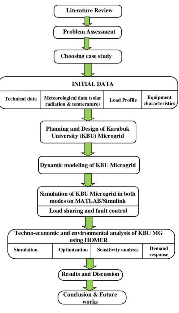
Figure 1.1. Methodology flow chart of the thesis. ... 5
Figure 2.1. Typical Microgrid structure . ... 15
Figure 2.2. Power exchange between distribution network and MG. ... 17
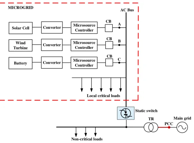
Figure 2.3. Schematic diagram of Microgrid. ... 18
Figure 2.4. MG interconnection with a distribution network. ... 19
Figure 2.5. Classification of MGs based on operational frequency. ... 20
Figure 2.6. DC Microgrid system . ... 21
Figure 2.7. DC Microgrid system ... 23
Figure 2.8. Typical structure of LFAC MG. ... 24
Figure 2.9. Typical schematic chart of HFAC MG. ... 26
Figure 2.10. Topology of Hybrid MG. ... 27
Figure 2.11. Common standards used for a general MG architecture . ... 29
Figure 2.12. IEC 61850 Standard Structure. ... 31
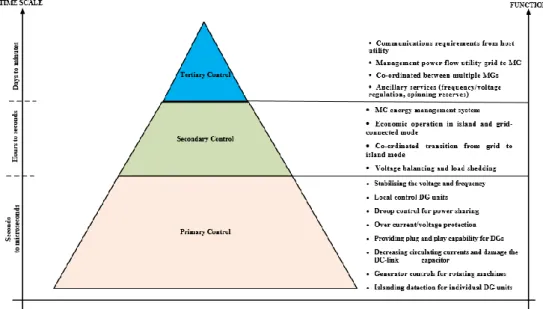
Figure 3.1. Control strategies of MG and their main functions. ... 36
Figure 3.2. Classification of MG control strategies. ... 37
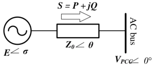
Figure 3.3. Equivalent circuit of connection between VSC and AC bus. ... 44
Figure 3.4. Conventional droop method. ... 45
Figure 3.5. Small-signal model (conventional active power control) [56]. ... 45
Figure 3.6. The principle behind the secondary control strategy in MGs [61]. ... 47
Figure 3.7. Centralized secondary control structure [21]. ... 50
Figure 3.8. Decentralized secondary control structure... 52
Figure 3.9. Distributed secondary control of MG [99]. ... 55
Figure 3.10. Structure of tertiary control in MGs. ... 57
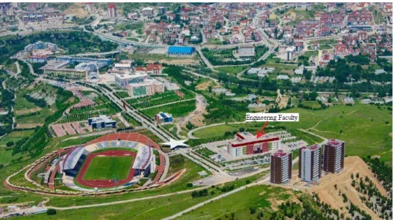
Figure 4.1. Engineering faculty in Demir Celik Campus of Karabuk University. ... 60
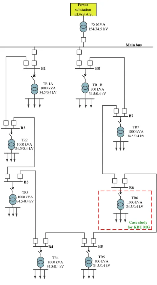
Figure 4.2. Electric power supply diagram of Karabuk University. ... 63
Figure 4.3. Microgrid single line diagram of KBU Engineering faculty. ... 64
Figure 4.4. Overall structure of KBU MG in grid-connected mode. ... 65
Figure 4.5. One phase model of MV transmission line. ... 67
xiv
Page
Figure 4.7. Single block representation of MV transmission line... 67
Figure 4.8. Block diagram of three-phase transformer. ... 68
Figure 4.9. Single block of transformer. ... 68
Figure 4.10. Model of voltage receptor load. ... 69
Figure 4.11. Model of current receptor load. ... 70
Figure 4.12. Single-line diagram of grid bus. ... 71
Figure 4.13. Block diagram of grid bus. ... 71
Figure 4.14. The single line diagram of MV bus. ... 72
Figure 4.15. The block diagram of MV bus. ... 73
Figure 4.16. Coupling MV bus. ... 74
Figure 4.17. Overall Microgrid architecture. ... 74
Figure 4.18. The overall model of KBU MG in islanded mode. ... 76
Figure 4.19. The model of a conventional diesel engine synchronous generator system. ... 77
Figure 4.20. Synchronous machine abc stationary frame and 0dq rotating frame association. ... 78
Figure 4.21. Electrical model of a generator in the abc frame. ... 79
Figure 4.22. The model of electrical generator in the 0dq reference frame. ... 82
Figure 4.23. Equivalent electric circuit of a PV cell. ... 83
Figure 4.24. I (V) characteristic of a PV panel. ... 86
Figure 4.25. Flow chart of P&O method. ... 88
Figure 4.26. Circuit model of a typical battery. ... 90
Figure 4.27. The equivalent model of three-phase inverter [133]... 90
Figure 4.28. Block diagram of VSI control loops. ... 91
Figure 4.29. Configuration of static switch. ... 92
Figure 4.30. Main grid and MG connection via static switch. ... 92
Figure 5.1. Flow chart of load sharing and fault control of KBU MG system. ... 96
Figure 5.2. Simple Microgrid system. ... 97
Figure 5.3. Single line diagram of Karabuk university microgrid. ... 98
Figure 5.4. Simulink model of fault and power flow control of MG system. ... 100
Figure 5.5. Simulink model of the inverter control. ... 101
Figure 5.6. Simulink model of the solar PV with grid connected inverter. ... 101
Figure 5.7. Simulink model of the battery. ... 102
xv
Page
Figure 5.9. Simulink model of the three-phase transformer. ... 103
Figure 5.10. Simulink model of the load profile. ... 104
Figure 5.11. Simulink model of the fault control system. ... 104
Figure 5.12. Load profile and circuit breaker signal for different loads. ... 105
Figure 5.13. Power characteristics of grid, solar PV, battery and diesel generator. 106 Figure 5.14. Fault details and fault voltage at area. ... 107
Figure 5.15. Critical and non-critical load profiles while the fault. ... 107
Figure 5.16. Grid voltage and current at the primary transformer. ... 108
Figure 5.17. Grid voltage and current at the secondary transformer. ... 109
Figure 5.18. Voltage and current of PV-battery bus. ... 109
Figure 5.19. Voltage and current of diesel generator. ... 110
Figure 5.20. Load voltage and current at diesel generator. ... 111
Figure 5.21. Load voltage and current at PV-battery bus. ... 112
Figure 5.22. Load voltage and current at secondary of the transformer. ... 113
Figure 5.23. Frequency response on grid-connected and island modes. ... 113
Figure 6.1. Flow chart of the methodology steps for KBU MG analysis. ... 116
Figure 6.2. System architecture of KBU MG in Homer Grid. ... 118
Figure 6.3. Daily profile of critical loads. ... 119
Figure 6.4. Seasonal profile of critical loads... 119
Figure 6.5. Daily profile of non-critical loads... 119
Figure 6.6. Seasonal profile of non-critical loads. ... 120
Figure 6.7. PV loads profile consumption (kW) of months with respect to hours. . 121
Figure 6.8. Generator loads profile consumption of months with respect to hours. 121 Figure 6.9. Monthly temperature graphic of Karabuk province. ... 122
Figure 6.10. Solar global horizontal irradiation. ... 123
Figure 6.11. Comparison of NPC between base case and lowest cost system configuration. ... 130
Figure 6.12. Annual savings of the proposed (winning) system by categories... 131
Figure 6.13. Monthly average electricity production for proposed system. ... 131
xvi
LIST OF TABLES
Page
Table 2.1. Advantages and drawbacks of DC MGs versus AC MGs. ... 22
Table 2.2. Advantages and drawbacks of AC MGs [36]. ... 23
Table 2.3. MG related standards developed by IEC and IEEE. ... 28
Table 5.1. Specification of KBU Microgrid. ... 99
Table 5.2. Active power sharing of KBU MG system. ... 106
Table 6.1. Case-wise comparison of optimization results. ... 128
Table 6.2. Comparison of electricity production and consumption. ... 129
Table 6.4. Case-wise comparison of yearly emissions. ... 130
Table 6.5. Generator statistics. ... 132
Table 6.6. Generator quantities during outage. ... 132
Table 6.7. Demand response and revenue. ... 133
Table A.1. Technical specification of the KBU substation transformer TR 6 .... 154
Table A.2. Technical specification of the distribution center transformer ... 154
Table B.1. Technical specifications of PV panel CWT300-72M ... 156
Table B.2. Technical specification of battery MUTLU 6OPzS-300 ... 157
Table B.3. Technical Data of Inverter ABB TRIO-50 ... 157
Table C.1. Load profile of Engineering faculty ... 160
Table D.1. Critical loads list of Engineering faculty. ... 163
xvii
SYMBOLS AND ABBREVITIONS INDEX
SYMBOLS
αβ : stationary reference frame dq : synchronous reference frame abc : natural frame
ABBREVITIONS
RES : Renewable Energy Sources DER : Distributed Energy Resources PV : photovoltaic
LV : low-voltage MV : medium-voltage DG : distributed generation KBU : Karabuk University MG : Microgrid
SG: : Smart Grid
CERTS : Consortium for electric reliability technology solutions PCC : Point of common coupling
SS : Static switch
PFC : Power factor corrector
LFAC : Line-frequency alternative current HFAC : High-frequency alternative current UPLC : Universal power line conditioner UPQC : Universal power quality conditioner EPS : Electric power system
IEEE : Institute of Electrical and Electronics Engineers IEC : International electro-technical commission
xviii SCC : Standards coordinating committee
ACSI : Abstract communication service interface SCSM : Specific communication service mapping IED : Intelligent electronic device
SAS : Sub-station automation system UAS : Utility automation system LN : logical nodes
SCL : System configuration language SRD : Source requirement documents MPPT : Maximum power point tracking PLL : Phase locked loop
ESS : Energy storage systems VSC : Voltage source converter
VCVSI : Voltage-controlled voltage source inverter THD : Total harmonic distortion
MGCC : Microgrid central controller MAS : Multi-agent system
CSI : Current source inverter VSI : Voltage source inverter BESS : Battery energy source system EMS : Energy management system
NREL : National renewable energy laboratory NPC : Net present cost
COE : Cost of energy
TSMS : Turkish state meteorological service RF : Renewable fraction
1 PART 1
INTRODUCTION
The energy demand is growing exponentially in the world. Hydrocarbon resources are depletable and limited in supply. It is predicted that the energy consumption in the world will increase until 216500E×106 TW in 2035 [1].Year by year it is difficult to
maintain the operation of power systems taking into account all requirements - technical, economic and environmental. To support all of these requirements, the introduction of intelligence is required in the interest of efficiency, safety and economy, thereby creating prerequisites for the emergency of "Smart Grid" concept. These problems have led to new concept of "Smart Grid".
Hydrocarbons are the main sources to generate electricity. However, the limited availability of fossil fuels, rising fuel prices and environmental pollution from burning fossil fuels have cast doubt on the future viability of human civilization, which depends on traditional energy sources. In recent year, in many countries the share of renewable energy sources (RES) in the energy generation has been increasing due to their positive impact on addressing environmental concerns as a clean energy source, low expenses for operation and maintenance, easy setup. The total renewable energy installed capacity at the world was 2356,3 GW in 2018, and energy total production of renewable energy resources was 6190948 GWh at the end of 2017 [2].
Last decades a lot of projects, research works have been focused on microgrid (MG) as it is intended to improve operation and maintenance of power system, increase the reliability and decrease carbon dioxide emissions.
2
Microgrid defines as collection of distributed energy resources (DER) and loads that operates as single system. In last decades, the developing of power electronics units give to equip DERs, and thereby to provide the flexibility operation of power system with integrated microsources as a single aggregated system.
Also, MG is an interconnection of distributed generation such as microturbines, wind turbines, photovoltaics (PV), and storage devices and interior loads which operate at low-voltage (LV) and/or medium-voltage (MV) distribution network. Such a single system gives a new problem, such as provide a stability while intermittency of renewable energy sources, power quality, etc. These issues should be resolved by applying advanced technologies at LV/MV distribution network of power systems.
In this work, the microgrid is planned, designed and modeled for Engineering faculty building at Karabuk university (KBU) campus. The results for simulation, technical-economic assessment of KBU Microgrid are executed by licensed HOMER Grid version 1.6.1 software tool. HOMER Grid program developed by the National Renewable Energy Laboratory (NREL) and implements the simulation, optimization, sensitivity and demand response analysis.
1.1. PROBLEM STATEMENT AND MOTIVATION OF THE THESIS
Penetration of DERs into the power system caused new area for research such as:
• the issues with reliability and efficiency of the SG system;
• how to plug in and interface storage devices to distribution networks; • how to support the flexibility energy generation;
• digitalization of the energy system.
Conventional power systems are designed to operate radially and not considered the integration of distributed generation at LV network. The high penetration of distributed generation (DG)s to power systems disrupts smooth operation of the system and creates the following issues:
3
• The complexity of system control increases • Additional protection should be provided
• Communication difficulty of distribution systems.
Therefore, there is a problem with to integrate one or a several MGs into LV/MV networks or customer sides by properly coordinating the operability of DERs, energy storage systems and neglecting their potentially negative side effects on operation and control of power systems.
Variety sources of DG and loads are a reason of high nonlinearities, changing dynamics, and uncertainties. For example, some RES such as solar PV and wind turbines work under unpredictable environmental conditions and turbulent. To solve these issues, it requires to develop intelligent control strategies, and thereby to increase reliability and performance of power systems. And thus, MGs performance strongly depend on the applied control strategies. So, the operation of power electric system and MGs are essential to provide reliability and security of the power system. Based on the foregoing, in this work, the modeling and simulation of Karabuk university microgrid are developed, considered operation modes and control strategies of microgrid.
1.2. RESEARCH OBJECTIVES
In conventional power system, the distribution network is passive, because it is designed as centralized system where generated energy transmitted power from transmission system and distribute to customers and there is no distributed generation. While the integration of distributed generation within distribution network power systems become an active with bidirectional power flows.
Main purpose of work is to design the model of MG for a one substation of KBU campus and development the control strategy for efficiently operation of a KBU microgrid. The simulation model of microgrid demonstrates the coordination strategy of DERs as an effective way of optimizing the economic operation and the reliability of MGs.
4
The specific objectives of this thesis are following:
• Design of microgrid for one substation of KBU electric network; • Microgrid dynamics representation and modeling;
• Develop control strategies of microgrid;
• Simulation of microgrid in grid-connected and isolated operation modes; • Load sharing control of distributed energy sources;
• Fault control of microgrid;
• Techno-economic and environmental analyzing of KBU microgrid.
1.3. METHODOLOGY
The integration of DERs and energy storage devices to existing power distribution network makes problems such as to provide the operating reliability and efficiency of electricity system. Therefore, precise design and modelling microgrid system with control ensure the stability of power system.
The methodology flow chart of the research is given in Figure 1.1. In methodology the problem of research has appreciated and evaluated according to the literature review. Then appropriated case study for the research work has been chose and gathered required initial data. Planning and design of KBU MG are implemented based on initial data. Dynamic and mathematical modeling of microgrid have executed as previous step to perform the simulation of KBU MG on MATLAB/Simulink. Load sharing and fault control strategy of KBU MG are developed on MATLAB/Simulink in next stage of the research. Techno-economic and environmental analyses are executed using licensed HOMER Grid version 1.6.1 software tool to evaluate the effectiveness of MG application.
5
Planning and Design of Karabuk University (KBU) Microgrid
Dynamic modeling of KBU Microgrid
Results and Discussion
Simulation of KBU Microgrid in both modes on MATLAB/Simulink
Problem Assessment Literature Review
Technical data
INITIAL DATA Meteorological data (solar
radiation & temterature)
Equipment characteristics Load Profile
Choosing case study
Load sharing and fault control
Simulation
Techno-economic and environmental analysis of KBU MG using HOMER
Optimization Demand
response Sensitivity analysis
Conclusion & Future works
6 1.4. LITERATURE REVIEW
The first scientific work related to microgrids was presented by R. H. Lasseter [3]. In the article, he describes the microgrid paradigm and gives its overview, which includes its architecture, protection, control, and energy management.
T. Ackermann et al. [4] have discussed the objectives and problems of commonly defining the concept of distributed power generation. They defined it according to the guidelines provided in the literature. Moreover, distributed resources, capacities, and utilities have been discussed. Also, this paper describes technologies for distributed generation.
R. H. Lasseter et al. [5] in their work related to research projects, published by Consortium for Electric Reliability and Technology Solutions (CERTS), which describes in detail the MG technologies for creating MGs. A major and significant feature of Microgrids is the interconnection between the Microsource Controllers. Such devices of power electronics maintain balance of energy and quality of power by means of passive plug-and-play inverter features, which help the overall operation with no fast communication and central active control.
An article by N. Hatziargyriou et al. [6] described the ongoing researches, developments, and show the operations of a microgrid, which is going on in United States, European countries, Canada, and Japan. MGs, which are equipped with DERs (distributed energy resources) that perform in a decentralized way, reduce the burden of control on a grid. The same article describes that every microgrid is equipped with an LV local DERs, which functions as a single producer with the grid, and they are important for power generation and energy marketing. Generally, microgrids safely and efficiently operate in a local network with islanding capability.
S. Chowdhury et al. [7] published a research that throws light on the concepts, effects, generation technologies, operations, management, and financial viability of MGs and broad perspective of their active distribution networks. They are the basic ideas behind MGs as well as their distribution networks, requirements of such networks, challenges,
7
technical advantages, socioeconomic impact and issues pertaining to their management and operations. The researchers have discussed the operational principles of different DERs, which are generally applied to Microgrids as well as active distribution networks, and their impact. Some microgrids show substantial effect on the operations of the main grid and its customers. The current research lists economic, technical, and environmental advantages of MGs. In this research, their protection systems, power electronic interface development, power quality, control, reliability matters, and distribution have been discussed in detail.
N.Hatziargyriou [8] provides details in his work, which deals with understanding, analyzing and justifying Microgrids as a new distribution network structure that discovers the full potential of Distributed Energy Resources (DERs), and thus, it is a basic block of smart grids, a well-thought view of the microgrid concept from the various forms of potential economic, environmental and technical benefits. This work presents results of EC-funded research projects such as “Advanced Architectures and Control Concepts for More Microgrids” and “Large Scale Integration of Micro-Generation to Low Voltage Grids,” which were conducted from 1998 to 2006. That shows the role of microgrids in the power system structure focusing on their major findings specifically pertaining to primary and secondary controls, microgrid management, and multiple-microgrids. The book describes the hierarchical control levels distinguished in Microgrids’ operations, the principles and main functions of centralized and decentralized control, including forecasting and state estimation. It also provides results of quantified assessment of the Microgrids benefits from economic, environmental, operational and social points of view. Finally, an overview of the basic multi-agent systems concepts and their application to decentralized control of Microgrids is provided.
In another article, which has been published [9] to review the DERs and microgrids, the authors H. Jiayi et al. introduced the updates on MGs and their architecture. This paper describes architecture of microgrid, MG operation modes, fault detection and safety analysis of MGs. It also throws light on the market of MGs.
8
In the paper published by M. Barnes et al. [10], global MG projects have been described. MG concept and structure are presented described by authors. Their hardware range and operational controls are also reviewed. It highlights and summarizes the operating principles, field trials, and key conclusions.
Microgrid architectures and models have been reviewed in a study by M.S. Mahmoud et al. [11]. In this research, the authors have reviewed various control schemes for microgrids. MGs are discussed as a “system of systems” and their applications have been highlighted.
In a paper written by F. Martin-Martínez et al. [12], the overall literature review has been given, which discusses MGs in detail. The authors represented basic definitions, structures and architecture of MG. In this article, exhaustive analysis of each MG’s physical layer has been conducted. The physical layer has been analyzed that compares AC and DC, shows a clear physical division, and reviews DC voltage grids (Picogrids, Nanogrids, and MGs) besides comparing MG technologies.
D. Olivares et al. described microgrid control strategies [13]. Their paper highlights the major challenges faced in the microgrid controls. They have also reviewed state-of-the-art trends and control strategies. Moreover, they have given an overview of some control principles.
F. Katiraei et al. [14 ]cited MG structure and characteristics, DER units and MG loads. They classified control types of MG. Their article shows the main differences between huge power systems, microgrids, and provides a new controlling approach besides other microgrid operational concepts.
According to Z.Alibhai et al. [15], there are four major types of auction, which are used for MGs. They have presented some simulation results and techniques for managing energy sources and loads using MGs in a single community. In some situations, when there aren’t many sources and loads, the auction type largely depends on the buyer’s priorities. In case of several sources and loads, Dutch auctions are preferred.
9
P. B. Shashi et al. [16] presented a method to build MGs, which are cost-optimized and have reliability constraints. Their process determines optimal interconnection between the lead points and MS, and it is based on dynamic programming, when their possible interconnections are given.
In another article [17], E. Ghiani et al. explained an algorithm, which can be applied to explore the MGs optimal combination, for reconfiguring the distribution system. In search of the best combination of MGs with the most appropriate configuration, Sequential Monte Carlo simulation has been applied. The algorithm found the final structure, maximized the cost savings and minimized the service interruption cost.
Another paper [18] explains the MG architecture in a clear distinction addressing and reviewing the currently applied communication protocols. This paper culminates with a detailed and practical MG review and discussion on its key points of deploying MGs. It contributed to the existing knowledge by clearly defining the MG uses, specifically in the electric systems of the future.
A study [19] has been conducted to show the latest comprehensive literature review of DC and AC MGs in terms of distributed generation (DG) units with the help of energy storage systems (ESS), renewable energy sources (RESs), and loads. It includes a survey on the configurations of the LV alternative DG units. It also investigated the control, feasibility, and strategies to manage energy in two microgrid systems. This paper gives an introspective review of the DC and AC MGs using renewable DG units, loads, and storage devices, which are mentioned in the recent literature. It also describes the issues linked with traditional distribution systems, and MG roles and influences. It tries to address the general challenge, which is how to optimally run every MG component in optimal operating conditions.
Another study presented the state-of-the-art researches on energy management and control strategies for DC MGs [20]. This work has been broadly classified in two categories, which are based on distinguishing characteristics shown by the control strategies. This paper was written with a purpose to show an up-to-date overview of DC networks, their controls, their secondary factors, and the most common
10
instruments. The analysis has been performed using systematic literature review method, which helps locating and classifying the existing analysis, literature, and synthesis, which identifies the interconnection between papers to reasonably derive some useful conclusions, and they show what has been found and what is not. In both cases, the previous research and analysis is carried out, which is useful for new researchers. The authors also highlighted some interesting research questions, which experienced researchers might use for their research.
The ESS structures and technologies have been reviewed by the authors of a research paper [21], in which, they have presented their classifications, configurations, energy conversion, features, and evaluation. In addition, benefits and flipsides of ESS in MGs have been assessed in terms of energy formation, power transfer mechanism, material selection, efficiency, capacity, and cycle duration. Some reviews had critical judgments regarding some current technologies such as ESS in MGs. Even now, optimum ESS management for efficient MG operations is an issue for the latest power systems. The review highlighted some issues, key factors, and challenges giving recommendations to further develop ESS in MGs. The highlights of the current review have significantly contributed to the effort for developing an efficient and cost-effective ESS model that has a prolonged life cycle to implement sustainable MGs.
J. M. Guerrero et al. presented in their paper [22] the hierarchical controls on three different levels: primary, secondary and tertiary. These three levels applied to AC and DC microgrids. The primary control includes the use of droop method, which includes a virtual loop while the secondary control helps restoring deviations, which have emerged through primary controls. A tertiary control performs power flow management between the external distribution system and the MG. In the paper, advantages and drawbacks of each level have been explained.
A research [23] provided some recommendations and guidelines to suit the needs of researchers and designers which are helpful to address the emerging challenges while handling actual microgrids. In order to accomplish this task, a literature review was given that outlines the main design features and the main control functions, which
11
assure security, economy, reliability, and secure operations in different transitions and operating modes.
A paper [24] describes a research has been conducted on technologies, microgrid standards, and applications, which allow this concept’s successful implementation. Basically, IEEE 1547 Standard was explained in this work. The author described the IEEE 1547 Standard approach to microgrids.
Another research was conducted on hybrid AC-DC microgrids [25], which have attracted considerable attention. It discussed the topologies for the AC/DC hybrid MGs, discussed the AC/DC interconnection, and explained some traditional power networks. After describing and analyzing each configuration, some important features were also highlighted. The future trends show that many features, including the modeling, scalability, or design need further research for integrating hybrid microgrids with an existing power network.
The researchers performed a continuous research on microgrids and reported their findings in an article [26]. This research reviews the hybrid AC-DC microgrid control strategies, which can be implemented for adequate power supply and management in both islanded and grid-connected operations. Their review mainly focuses on hierarchical controls which are part of an extended approach. They classified and elaborated it to cover three main hierarchical control strategies (mentioned as primary, secondary and tertiary in a previous part of this document). Each level was independently studied for providing comprehensive analyses.
The literature review of architecture, policy and future trends of MGs has been presented in another research paper [27]. The benefits and issues of such configurations are also mentioned in the study. RES has its own advantages and its power quality issues. The energy storage systems have certain benefits, which help developing communication systems, and assure efficient but flexible smart grid operations. Their findings are outlined along with the discussion on the policies and trends of microgrids.
12 PART 2
MICROGRIDS ARCHITECTURE
One of the major power systems’ crises has been the conventional system’s inability to deal with the mentioned issues because they require massive overhauling, which is not cost-effective. Besides, it needs intelligent command and control systems in place for connecting the power grids. Even now, such technology could not be introduced to improve the transmission systems of the existing electricity grids. This requires improved electrical grids, also termed as Smart Grid (SG), which has provided an alternative to conventional electricity transmission in the centralized networks. The evolution of the traditional power grid towards smart grid involves the grid transformation into microgrids (MG), which is a key SG component to improve power efficiency, reliability and reduce polluting emissions. Such microgrids combine storage devices (energy capacitors, batteries, and flywheels), distributed energy resources, and flexible loads. They are connected to the main power grid through switches.
2.1. MICROGRID CONCEPT AND STRUCTURE
The microgrids were first launched and introduced by the European Commission’s Project on Micro-Grids and Consortium for Electric Reliability Technology Solutions (CERTS), which defined MG as follows:
CERTS [5] mentioned that a “microgrid consists of micro-sources and a cluster of loads that operate like a single controlled system providing both heat and power. Such microgrids are electronically interfaced to enhance the quality and reliability of power supply”.
13
EU research projects [27] defined them as: “Microgrids are LV distribution networks, which connect distributed energy resources (DERs) (fuel cells, microturbines, wind turbine, and PV) with storage devices including energy capacitors, flywheels, and batteries to assure flexible loads.
MGs are mainly active distribution networks because they operate the DG systems at different distribution voltages. An MG is connectable to low-voltage distribution network. However, they also operate in the islanded mode when there are main network faults. Thus, the generators/micro-sources used the MGs generally have renewable/unconventional distributed energy resource (DERs), which are interconnected to generate power. Operationally, the microsources have power electronic controls and interfaces for providing the needed flexibility for assuring operations like a single aggregated system besides maintaining power output and quality. The controlling flexibility allows a microgrid to connect to the main system through a single control process to meet the local power requirements in a secure and reliable way.
MGs and conventional power systems are different in the following ways:
• Micro-sources have substantially lower smaller capacities as compared to conventional generators.
• The utility distribution network directly feeds on the power generated at distribution voltage.
• Micro-sources are generally placed closer to the clients’ premises to efficiently supply the required heat/electric loads assuring sufficient frequency profile and voltage while minimizing the line losses.
The MGs are normally equipped with storage systems, DERs, communication systems, distribution systems, and control systems (see Figure 2.1). The MGs have the following main components:
14
• Distributed sources like PV panels, fuel cells, small wind turbines, gas and diesel micro-turbines
• Storage devices like super capacitors, batteries, and flywheels; and • Critical/non-critical loads.
Since the RESs have fluctuant and intermittent availability, MG are equipped with a small hybrid power system that assures high energy security levels because of the combination of various generation systems, which generally incorporate ESSs for assuring highest possibility power supply reliability. Different hybridization types of power sources are part of an MG. As mentioned earlier, the RESs have intermittent availability, the backup power units assure high energy security levels. For instance, a micro-gas turbine, a diesel generator, and some fuel cells are used to assure interruption-less power supplies. The primary sources of renewable energy have definitive complementary benefits, such as the hybrid PV-wind systems are advisable to be used in certain areas because the solar PVs generate power only during the day; so, wind produces more power specifically if there are strong winds at night. When the energy storage devices are connected to the RESs, it assures the much needed power security and reliability, and it maximizes the gains out of renewable energy systems. Such systems optimally adjust deficits and excesses of produced energy using the energy storage units, which augments the overall energy efficiency [28].
15
Figure 2.1. Typical Microgrid structure [29].
2.2. MICROGRID OPERATION MODES
16
• It operates autonomously in the islanded mode;
• It is connected to the main grid in grid-connected mode
When it is stand-alone, loads are provided through microsources with sufficient power, but the MG does not connect with the main grid.
When it is grid-connected, MG completely or partially connects to the MV distribution network and generates extra power for providing auxiliary services. The MG-distribution distribution network power exchange has been illustrated in Figure 2.2. The power-exchanging grid-connected mode has the following operations:
• power-matched operations • power-mismatched operations
The power-matched operations involve the flow of active and reactive powers through the point of common coupling (PCC) that equals zero: ΔQ=0 and ΔP=0 while the current in the PCC is IPCC=0; therefore, balance has been created among the distributed generation
(DG) power flows and load powers while the operation is economic.
The power-mismatched operational mode is used when ΔP ≠ 0 or ΔQ ≠ 0; consequently, IPCC ≠ 0, which shows that power exchange takes place between the MG and the
distribution network. So here, when ΔP < 0, the extra DG active power is provided to the distribution networks but when ΔP > 0, the DGs electricity is not sufficient to meet the local demand, which is then provided through the distribution network. In the same way, there is extra reactive power when ΔQ < 0 and deficiency when ΔQ > 0. These functions are normally power-mismatched [30].
17 ΔP+ΔQ PCC Load Battery DG Utility grid
Microgrid Distribution network
Figure 2.2. Power exchange between distribution network and MG.
The MGs general structure is capable of operating in islanded as well as connected modes, as Figure 2.3 shows. Most of the MGs have radial feeders (A, B and C) that act as parts of the distribution system architecture and supports load collection. The mentioned radial systems are linked to the distribution system at the PCC through a static switch. PCC separates the main grid from the MG, and it is on the primary side of the transformer. Every feeder is equipped with a microsource controller and a circuit breaker [31]. The local critical loads are linked to the local generation resources whereas the non-critical loads have no local generation. A static switch can perform islanding of the MG in case when the disturbances happen, or when maintenance is needed. In emergencies, such as a main grid issue, MGs are disconnected through an SS just in a single cycle, which takes place very smoothly. MG are intentionally islanded intentionally as well, and this is done for specific reasons. It is also done when no fault or disturbance occurs in the main grid. The demand-generation balance is a significant requirement of the MG management systems both in islanded and connected operational modes [32].
Different segments of the MG architecture include loads, LV network, energy storage units, controllable and uncontrollable generation, and a hierarchical control (see Figure 2.4). A communication infrastructure supports the control scheme, which monitors and controls loads and power generators. The hierarchical control system has a center, known as the MGCC. When there is low hierarchical control level, the micro-source controllers
18
(MCs) and load controllers (LCs) exchange information with the MGCC. It manages the MG operation and provides the LCs and MCs with some set points. Normally, MGs are centrally managed and controlled through the MGCC, which is installed at the sub-station MV/LV. MGCC performs many functions, including the cost management and control of the MG hierarchical control systems.
Solar Cell Converter Microsource
Controller
CB
Static switch
TR Main grid
PCC Local critical loads
Non-critical loads A Wind Turbine Converter Microsource Controller
Battery Converter Microsource
Controller B C MICROGRID CB CB AC Bus
Figure 2.3. Schematic diagram of Microgrid.
When the outages or failures take place in the main grid, an MGCC synchronizes the main grid with the MG. The interfaces of power electronics connect the available DGs with the MG’s electric network. When the number of MGs is high in LV sub-stations, we should expect technical benefits in the main grids because of a multi-MG operation. The MGs interconnection to the distribution power network has been shown in Figure 2.4.
19 Fuel Cell Microsource Controller CB Static switch TR PCC MICROGRID MV MGCC Microsource Controller Microsource Controller Load Controller Load Controller Battery Load Microsource Controller Load Controller Microturbine Load Load PV-array LV Main grid CB CB CB Distribution network
Figure 2.4. MG interconnection with a distribution network.
A distinctive feature of the MG is the MG operation in an islanded mode, i.e. MG disconnects from a main grid distribution network while the power is provided by distributed generation during the failure or outages. An MG failure might result in the rise in the ground potential when the energy sources function at the LV level; therefore, grounding of DGs and connecting the MG to a utility network through a transformer should be carefully assessed because they need developing appropriate rules. The earthing systems of the LV depend on the earthing techniques, which are on the MV/LV transformer’s secondary side.
20 2.3. MICROGRID TYPES
The MGs according to operational frequency can be classified in the following configuration [33] (Figure 2.5):
1. DC Microgrid. 2. AC Microgrid.
2.1. Line-Frequency AC Microgrid 2.2. High-Frequency AC Microgrid
3. Hybrid Microgrid (AC and DC coupled MG).
MICROGRID
Hybrid DC and
AC Coupled
Microgrid
High-Frequency
AC Microgrid
Line-Frequency
AC Microgrid
AC Microgrid
DC Microgrid
21 2.3.1. DC Microgrid
In DC microgrids, there is interconnection between large percentage of the sources, energy storage, through a single or a few DC busses. Normally, DERs produce DC power, which no power quality issue. Figure 2.6 shows a DC MG configuration system. DC MGs certainly have certain advantages over AC MGs [12,34,35]. Table 2.1 shows benefits and issues of DC MGs versus AC MGs. DC MGs have a great benefit of lower line losses because the power factor correction circuit are unnecessary during the AC/DC conversion stage. The DC characteristics also reduce the losses because it does not show issues like skin effects, current harmonics, or reactive power. Moreover, when a voltage sag a blackout takes place, the DC bus voltage does not change because the capacitor stores power and the AC/DC converter keeps on working. Besides, there is no need to change wires, which support the voltage levels. Using DC has its own issues like it needs
expensive and complex distribution systems protections. Another issue with DC MGs its requirement of AC power supply to connect the AC loads directly to the DC bus; so, it needs a DC-AC converter. In addition, when AC is used for the purpose of distribution, a DC microgrid connects to the AC grid at the same time; therefore, DC microgrids should be equipped with AC buses as regular components of a mixed AC/DC microgrid that is coupled with the AC grid at point PCC [36].
22
Table 2.1. Advantages and drawbacks of DC MGs versus AC MGs.
Advantages Disadvantages
Lower losses Complex protection system
No harmonics Absence of zero-crossing points
No reactive power Higher levels of voltage
No synchronization of distributed generation
Inappropriate for HVDC transmission No power factor correction circuit Unavailability of Low-distance power
transmission No DC bus voltage changes when a
voltage sag/blackout happens
There is not telecommunication/wireless network interference
Efficiency of DC–DC switching regulators for certain loads.
Do not require changing wires under certain situations
2.3.2. AC Microgrid
Generally, AC type of MGs are commonly used because they directly implement the distributed generation power sources. Figure 2.7 illustrates an example of AC MG configuration system. AC MGs have high DG unit penetration, while the storage devices possess higher control flexibilities and capacities for connecting to traditional AC power systems both in islanding and grid-tied conditions but some new energy sources of a microgrid like batteries, solar generation, and fuel cells have substantial DC sources, which need inverters for connecting to the grid. Moreover, end users are increasingly adapting DC loads like computers and LED lighting, which need power factor correctors (PFCs) for AC- DC conversion. Establishing a DC power supply for connecting DC loads and sources using efficient DC/DC converters can decrease the control complexity and reduce the power conversion circuit. When this is performed, a DC grid shows its characteristics and have low power conversion cost and exhibit high efficiency [38]. In Table 2.2, the advantages and drawback of AC MGs have been shown.
23
Figure 2.7. DC Microgrid system [37].
Table 2.2. Advantages and drawbacks of AC MGs [36].
Advantages Disadvantages
1 2
Directly connect to distribution network via AC bus
The distributed utility and generation grid coupling need a synchronized AC bus No inverters require for power supply AC
loads
It substantially affects the power quality; for instance, induction machines and transformers produce
Easy and economic maintenance Generally, peak voltage is 1.4 times more than usual
The transmission of AC power is possible over long distances
Anxiety of three-phase unbalances in PVs emerge (single phase loads and generators).
Providing quick start generation by each DG to power supply, and the loads are generally in the islanded mode that automatically return to the grid-connected mode.
The reactive power should be monitored continuously
24
Table 2.2. Advantages and drawbacks of AC MGs (continued)
1 2
Protection of the system is low-tech, cheaper and modified
The AC system analysis work with complex number; therefore, it is complicated.
2.3.2.1. Line-Frequency AC Microgrid
In the common MGs, there are line-frequency AC (LFAC) microgrids. Generally, DERs are interconnected with MV/LV buses in the MGs. The DERs’ DC current is forwarded to AC with 50 Hz using DC-AC inverter and then transformed to loads. Various LFAC MG operational scenarios and concepts are given in the literature [33,36,39]. The typical structure of LFAC MG is illustrated in Figure 2.8. The three-phase LFAC MGs have more stages of power processing that reduce the system’s overall efficiency. This microgrid class requires different DC-DC, AC-DC, and DC-AC converters. For providing galvanic isolation or increasing the transmission line voltage, an LFAC microgrid needs heavy three-phase low-frequency transformers [40].
DC/AC DC/DC AC/DC/AC Converter DFIG PCC Gearbox Blades AC Power DC power Wind turbine system
Solar PV arrays DFIG G AC/DC/AC Converter Microturbine AC Power Critical Loads Critical Loads Critical Loads AC Line AC Line AC Line TR
Static switch Main grid
AC bus LV AC network LV AC network LV AC network Non-Critical Loads TR
25 2.3.2.2. High-Frequency AC Microgrid
High-Frequency AC (HFAC) MGs are only locally used because their losses dramatically increase with distance; so, it is suitable for small areas [41]. Applying HFAC for transmitting power through MGs is a novel concept but it is in its early stages. The conventional HFAC MG schematic chart has been shown in Figure 2.9. DERs are linked with a common bus. The DERs’ power generation is transformed into 500 Hz AC through power electronics devices that is transmitted to the load side where it is converted into AC 50 Hz through an AC/AC converter.
The distribution network is linked to the load side that guarantees effective interaction between the distribution network and the microgrid. On-the-line HFAC causes substantial reactance, causes more electricity losses and drop in voltage as compared to the 50 Hz AC power. Since microgrids are small-scale with short transmission distance; in that case, there is insignificant power loss and voltage drop.
HFAC MGs are equipped with electronic units, including a Universal Active Power Line Conditioner (UPLC), and a Unified Power Quality Conditioner (UPQC), A UPQC is compensates for the voltage distortions and the current harmonics through non-linear loads. It links the utility grid with the HFAC for performing functions such as controlling active/reactive powers and compensating for current harmonics, which might happen between the main grid and the microgrid.
Some researches [42,43] have highlighted the benefits and issues of HFAC MGs. Their advantages are given below:
• When the frequencies are higher, the higher order harmonics can be conveniently handled.
• The direct lighting equipment-HFAC microgrid connection effectively improves the power efficiency and the lighting brightness.
26
• It is possible to directly connect the HFAC line to the high-frequency AC motors or other high-frequency AC equipment that no longer requires transition devices. • The size of passive circuit components and high-frequency transformers has
become smaller and they are more compact.
• It is easy to connect the high-frequency resources to the storage units of a flywheel.
Besides such promising advantages, HFAC MGs have the following certain disadvantages:
• The HFAC technology enhances power losses and line reactance, which reduces the distance of power transmission.
• Along the line, HFAC results in substantial voltage drop.
• The HFAC MG control device is comparatively complex as compared to the traditional control devices.
DC/AC DC/DC AC/DC/AC Converter DFIG Gearbox Blades AC Power DC power Wind turbine system
Solar PV arrays DFIG G AC/DC/AC Converter Microturbine AC Power AC Line PCC
Static switch Main grid
AC Line Static switch AC Line Non-linear Loads Linear Loads UPLC UPQC 500 Hz AC Local Bus AC Bus Non-linear Loads Linear Loads AC Power HFAC Bus
27 2.3.3. Hybrid Microgrid
Hybrid microgrids are clusters of bi-directional converters, AC and DC microgrids, energy management system, and control equipment. Hybrid MG has been illustrated in Figure 2.10. It effectively integrates different DERs in a given distribution system. Hybrid AC- and DC-coupled microgrids bring the DC part in use to connect the distributed energy storage systems, which are part of the bi-directional AC-DC converters, and PV systems, which are connected by means of small turbines and DC-DC Boost converters through rectifiers. The decoupled AC and DC control is possible by using power converters [44]. Despite the fact that the hybrid MGs are flexible approach for integration between the DER structures, units, operations, and issues such as protection and stability, but it needs further investigation. WT SG Dump load device Diesel engine SG Consumers 220/380 V Consumers 6 or 10 kV TR Decentralized power supply object Diesel Generator DC bus Wind power plant Solar power station PV panel Converter SG Battery Energy storage Converter Inverter Inverter AC bus Field current regulator Diesel Generator Inverter Diesel engine Soft starter
28 2.4. STANDARDS FOR MICROGRIDS
Conventionally, the electric power systems (EPS) were unable to handle the active storage or generation process on the level of distribution. Such operational concepts and technologies integrate DERs in the already installed EPS, and they further develop so as to realize the operational advantages and reduce the issues pertaining to system safety and reliability. It is important to finalize a single document of consensus on the technical requirements for the interconnection of DERs rather than following several local guidelines and practices.
Some institutions, for example, the International Electro-technical Commission (IEC) and Institute of Electrical and Electronics Engineers (IEEE) have finalized some interoperability and interconnection standards for DERs with EPS. Different standards have been developed so as to address the critical needs through establishing a list of requirements and uniform criteria for the interconnection operation, performance, safety, testing, and maintenance. Table 2.3 shows some common MG-related standards, which were developed by IEC and IEEE.
Table 2.3. MG related standards developed by IEC and IEEE.
IEC
IEC/TS 62898-1 Microgrids. Part 1. Guidelines for microgrid projects planning and specifications
Published IEC/TS 62898-2 Microgrids. Part 2. Guidelines for operations Published IEC 62898-3-1 Microgrids. Technical Requirements.
Protection requirements in microgrids.
In development IEC 62898-3-2 Microgrids. Technical Requirements.
Self-regulation of dispatchable loads
In development IEC 62898-3-3 Microgrids. Technical Requirements. Energy
management systems
In development IEC 61850 Communication networks and systems in
substations.
IEEE
IEEE 1547 Interoperability and interconnection between the DERs with Associated Electric Power System Interfaces
29
Table 2.3. MG related standards developed by IEC and IEEE (continued). IEEE 2030 Smart Grid Interoperability Guide for Energy
Technology and IT Operations with the EPS, End-use Applications, and Loads
IEEE 2030.7 Specification of Microgrid Controllers
Figure 2.11 shows a general MG configuration containing DERs, static switches (SS), and loads at the common coupling point between utility grid and MGs. This figure indicates all common standards that can be used for MG energy management, monitoring, control, and protection systems. In this chapter we will consider the following main standards used for MGs architecture:
1. IEEE 1547 Series of Standard 2. IEC 61850 Standard
3. Ul 1741 Standard
30 2.4.1. 1547 Series of Standards
Arguably they are the most important standards for MGs. This series was developed by the IEEE Standards Coordinating Committee 21 (SCC21) on PVs, Fuel Cells, Energy Storage and Dispersed Generation in 2003 by the name as IEEE Std 1547-2003 (IEEE Standards for Interconnecting DERs with EPS). In 2014 IEEE 1547 was amended to IEEE Std 1547a™-2014 due to the changes in sub-clauses pertaining to the voltage and frequency responses to area of EPS under abnormal conditions, and voltage regulation.
IEEE 1547 has helped to modernize the traditional EPS infrastructure through laying the foundation to integrate the clean renewable energy generation with other ESS and distributed generation technologies. It provides compulsory technical and functional guidelines and provides choices and flexibility in terms of operations and equipment. IEEE 1547 also provides certain requirements for specific performances, operations, testing procedures, interconnection maintenance, and safety initiatives. It provides information about the response to abnormal conditions, general requirements, islanding, power quality, and requirements and specifications for design tests, production, commissioning, periodic tests, and installation evaluation. The mentioned requirements are required for DER interconnection for induction machines, synchronous machines, or power converters/inverters. They are sufficient in most cases.
The requirements and criteria apply to all the DER technologies, which have the approximate capacity 10 MVA or lower at the common coupling point, when the EPS is connected at typical primary/secondary distribution voltage. DER installation on radial primary/secondary distribution systems is an objective of the current document, for which, we considered the primary and secondary network distribution systems.
IEEE1547 recognizes that the distributed energy resources need to be integrated into the EPS Area in coordination with the operator. The functions specified in this standard may need to be supplemented in coordination with the Area EPS operator for specific situations.
![Figure 2.5. Classification of MGs based on operational frequency [33].](https://thumb-eu.123doks.com/thumbv2/9libnet/5397581.101907/39.918.194.801.491.998/figure-classification-mgs-based-operational-frequency.webp)

![Figure 3.5. Small-signal model (conventional active power control) [56].](https://thumb-eu.123doks.com/thumbv2/9libnet/5397581.101907/64.892.182.712.724.895/figure-small-signal-model-conventional-active-power-control.webp)
![Figure 3.6. The principle behind the secondary control strategy in MGs [61].](https://thumb-eu.123doks.com/thumbv2/9libnet/5397581.101907/66.892.171.827.655.1040/figure-principle-secondary-control-strategy-mgs.webp)