ContentslistsavailableatScienceDirect
The
Journal
of
Systems
and
Software
jo u rn al h om epa g e :w w w . e l s e v i e r . c o m / l o c a t e / j s s
S-IDE:
A
tool
framework
for
optimizing
deployment
architecture
of
High
Level
Architecture
based
simulation
systems
Turgay
C¸
elik
a,∗,
Bedir
Tekinerdogan
baDepartmentofComputerEngineering,HacettepeUniversity,Ankara,Turkey bDepartmentofComputerEngineering,BilkentUniversity,Ankara,Turkey
a
r
t
i
c
l
e
i
n
f
o
Articlehistory:Received30June2012
Receivedinrevisedform27February2013 Accepted1March2013
Available online 20 March 2013 Keywords:
Deploymentmodeloptimization Metamodelbasedtooldevelopment Distributedsimulation
HighLevelArchitecture(HLA) FEDEP
Softwarearchitecture Modeltransformations Metamodeling
a
b
s
t
r
a
c
t
OneoftheimportantproblemsinHighLevelArchitecture(HLA)baseddistributedsimulationsystems istheallocationofthedifferentsimulationmodulestotheavailablephysicalresources.Usually,the deploymentofthesimulationmodulestothephysicalresourcescanbedoneinmanydifferentways, andeachdeploymentalternativewillhaveadifferentimpactontheperformance.Althoughdifferent algorithmicsolutionshavebeenprovidedtooptimizetheallocationwithrespecttotheperformance,the problemhasnotbeenexplicitlytackledfromanarchitecturedesignperspective.Moreover,foroptimizing thedeploymentofthesimulationsystem,toolsupportislargelymissing.Inthispaperweproposea methodforautomaticallyderivingdeploymentalternativesforHLAbaseddistributedsimulationsystems. ThemethodextendstheIEEERecommendedPracticeforHighLevelArchitectureFederationDevelopment andExecutionProcessbyprovidinganapproachforoptimizingtheallocationatthedesignlevel.The methodisrealizedbythetoolframework,S-IDE(Simulation-IDE)thatwehavedevelopedtoprovide anintegrateddevelopmentenvironmentforderivingafeasibledeploymentalternativebasedonthe simulationsystemandtheavailablephysicalresourcesatthedesignphase.Themethodandthetool supporthavebeenvalidatedusingacasestudyforthedevelopmentofatrafficsimulationsystem.
© 2013 Elsevier Inc. All rights reserved.
1. Introduction
Simulationsystemsareusedtosimulaterealworldconcepts indifferentdomainssuchasmanufacturing,performanceanalysis, decisionsupport,virtualexercises andentertainment.Thereare differentreasonsforusingsimulationsystemsincludinganalysis andtesting,costreductionindevelopment,training,etc.Dueto thecomplexityofthesimulateddomainveryoftenthesimulation isexecutedacrossmultiplenodesandlikewiseseveraldifferent simulatorsareintegrated withinasingledistributed simulation environment.The reasonfor distributingthesimulation is usu-allyforreducingtheexecutiontime ofthesimulation, enabling geographicdistributionofsimulationparts,andenablinglarge sim-ulationswithalargenumberofusers(Fujimoto,1999).
Developingdistributedsimulationsystemsisnoteasybecause differentsimulatorsmightrunondifferentplatforms,adopt dif-ferentdatatypes,usedifferentcommunicationmechanisms,etc. Hence,animportantchallengeindistributedsimulationsystemsis theintegration,reusabilityandinteroperabilityofthevarious sim-ulators.Toreducetheeffortfordevelopingdistributedsimulations, severalstandardsimulationinfrastructureshavebeenintroduced
∗ Correspondingauthor.Tel.:+905054768307. E-mailaddress:[email protected](T.C¸elik).
including Distributed Interactive Simulation (DIS)(IEEE, 1998), High Level Architecture (HLA) (Kuhl et al., 1999; IEEE, 2010a), andTestandTrainingEnablingArchitecture(TENA)(Noseworthy, 2008).Amongthese,HLAisanimportantIEEEandNATOstandard specifiesa generalpurposesimulation architecturefor realizing interoperableandreusabledistributedcomputersimulation sys-tems(Kuhletal.,1999;IEEE,2010a).
OneoftheimportantproblemsinHLAbaseddistributed simu-lationsystemsistheallocationofthedifferentsimulationmodules totheavailablephysicalresources.Eachdeploymentalternative representsadifferentallocationofmodulestophysicalresources andthiscanbedoneinmanydifferentways.Further,each deploy-mentalternativewillhaveadifferentimpactontheperformance. Thisproblemcanbecategorizedasataskallocationproblemthat hasbeenwidelyaddressedintheliterature(Stone,1977;Lo,1988; Pirim,2006;Mehrabietal.,2009).Tosolvethetaskallocation prob-lemdifferentalgorithmicsolutionshavebeenproposed.Hereby, thealgorithmstakeasinputseveraloptimizationparameterssuch asexecutioncost,communicationcost,memoryrequirementand I/Ocost.Basedontheseinputparametersthetaskallocation algo-rithms aim to derive feasible allocation of tasks to processors (Stone,1977;Lo,1988).Theevaluationofthedeployment alter-nativeisusuallybasedonexpertjudgmentandpostponedtothe implementationphase.Onecannotalwaysrelyonexpertjudgment becausefindingexpertsthathave botha broad andspecialized 0164-1212/$–seefrontmatter © 2013 Elsevier Inc. All rights reserved.
knowledge onthe correspondingdomains is not easy. Further, humanexpertjudgmentscanbefeasibleforsmalltomedium sys-temsbutareinadequateforlargeandcomplexsystems.Moreover, postponingtheevaluationof thedeploymentalternativetothe implementationphase,might lead tonon-feasible implementa-tionswhichmayrequireunnecessaryiterationofthedesignand therelatedprojectlifecycleartifactssuchasdetaileddesign, imple-mentation,testartifacts,documentation,etc.Onitsturnthiswill leadtodelaysintheprojectscheduleandincreasedcostduetothe unnecessaryreworkofthelifecycleartifacts.
Theneedforearlyanalysisandoptimizationofthedeployment alternativeshasalsobeenaddressedbytheIEEERecommended Practice for High Level Architecture Federation Development andExecutionProcessFEDEP(IEEE,2003).FEDEPdescribes rec-ommendedtasks for evaluating alternative design options and estimatingthesimulationperformanceindesignphasebut delib-eratelydoesnotprovideadetailedprocessandimplementationfor theindicatedtasks.
Tocope withtheabove problemsand address theneedsas addressedbyFEDEP, weproposeamethodandourtool frame-workS-IDE (Simulation-IDE) that supports the earlyanalysis of deployment alternatives and the automatic generation of the deploymentalternativesforHLAbaseddistributedsimulation sys-tems. S-IDE tool framework consists of several tools based on metamodelsthat wehave developed includingFederation Data ExchangeMetamodel,SimulationModulesandPublish–Subscribe RelationsMetamodel,PhysicalResourcesMetamodel,Simulation ExecutionConfigurationMetamodel,andDeploymentMetamodel. Basedonthedesignmodelsdevelopedwiththesetools,the neces-saryparametervaluesforthetaskallocationalgorithmsaredefined, whicharethenusedforautomaticgenerationofafeasible deploy-mentalternative.Inaddition,thetoolframeworkcanbeusedfor designlevelanalysisincluding,theimpactofaddingnew simu-lationsmodulestothesystem,suitabilityoftheselectedphysical resourcesforthegivensimulationdesign,andtheimpactofthe changeofpublish–subscriberelations.Toillustratetheusageofthe methodandS-IDEwehaveusedarealisticcasestudyconcerning thedevelopmentofatrafficsimulation.
Theremainderofthepaperisorganizedasfollows.InSection2 weprovidethebackgroundonHLAandModelDrivenEngineering (MDE).Section3definestheproblemstatementbasedonacase studythatwillbeusedinsubsequentsections.Section4presents themethodforevaluatingalternativedesignoptionsbriefly. Sec-tion5describesthemetamodelsthatS-IDEtoolframeworkisbuilt on.Section6presentsthemodeltransformationsstepbystepfor derivingfeasibledeploymentalternatives.Section7provides real-izationofS-IDEtoolframeworkandusingS-IDEtoderiveafeasible deploymentalternativeforthecasestudy.Section8providesthe evaluationofthetool.Section9providesthediscussion.Section 10describestherelatedworkandfinallyweconcludethepaperin Section11.
2. Preliminaries
Inthissectionwedescribethebackgroundforunderstanding andsupportingtheapproachthatwepresentinthispaper.In Sec-tion2.1wepresentabriefdefinitionoftheHighLevelArchitecture (HLA),followedbyashortoverviewofModel-DrivenEngineering (MDE)inSection2.2.
2.1. HighLevelArchitecture(HLA)
Asstatedbefore,HLAisanIEEEstandardthatsupports develop-mentofreusableandinteroperabledistributedsimulationsystems (Kuhletal.,1999;IEEE,2010a,b,c).Tosupportthedevelopmentof
Ce ntra l Infra s tructure Node
<<Infra s tructure >> Ce ntra l RTI Compone nt (CRC)
S imula tion Node
1..* 0..1
Fe de ra te
<<Infra s tructure >> Loca l RTI Compone nt
(LRC) S imula tion Module
Ins ta nce
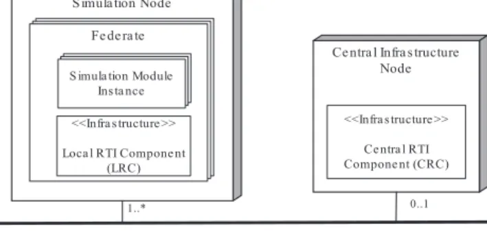
Fig.1. Referencearchitectureforthehighlevelarchitecture.
HLAcompliantsimulationsystems,the“FederationDevelopment andExecutionProcess–FEDEP”hasbeendefinedasapartofHLA standard(IEEE,2003).
BasedonadomainanalysistoHLAstandardwecouldderive thereferencearchitectureofHLAbasedsimulationsystemswhich isshowninFig.1.Atypicalsimulation systemisdeployedona numberofSimulationNodes.EachSimulationNodeincludesoneor moreFederateswhichareprocessesthattogetherformthe sim-ulationexecution.EachmemberincludesanumberofSimulation ModuleInstancesandLocalRTIComponent(LRC).Simulation Mod-uleInstancesrepresent objectsfor simulating entitiesor events inthesimulation.RTIrepresentstheruntimeinfrastructurethat realizestheHLAstandard(IEEE,2010a).LRCenablesbi-directional interactionbetweenfederatesfordataexchangeandcollaborative executionofthesimulation.
ThesimulationmayalsoincludeanoptionalCentral Infrastruc-ture Node that contains Central RTI Component (CRC) which is responsibleformanagingthesimulationlifecycle,timing, synchro-nization,anddiscoveryconcerns.Althoughthiscomponentisnot mandatory,asaconvention,majorRTIimplementationsprovide CRCdefinitions.IncaseCRCismissing,theservicesneedtobe sup-portedbytheLRCs.AssuchboththeLRCandCRCprovidesimilar services.InFig.1thisisindicatedthroughthestereotype «Infra-structure».
TheCRCand LRC implementations togetherprovideservices forfederationmanagement,declarationmanagement,object man-agement,ownership management, time management, and data distributionmanagement(IEEE,2010b).
Thebasicinteractionmodelthat isadoptedin theHLA con-formstothePublish/Subscribepattern (Eugster etal.,2003).In thePublish/Subscribepatterntheproducerandconsumer appli-cations(members)are decoupled.Thisincreasesthereusability andinteroperability,whicharekeyconcernsinsimulationsystems. ThePublish/Subscribeinteractionisrealizedbythe«Infrastructure» componentsinthereferencearchitectureinFig.1.Federatesin thesimulationexecutioncanpublishandsubscribedataexchange modelelementsthroughtheservicesprovidedbythe «Infrastruc-ture»components.HLAstandarddefinestheObjectModelTemplate (OMT)thatcanbeusedtodefinedifferentdataexchangemodels whicharecalledFederateObjectModel(FOM)andSimulationObject Model(SOM)(IEEE,2010c).
2.2. ModelDrivenEngineering(MDE)
Intraditional,non-model-drivensoftwaredevelopmentthelink betweenthecodeand higherleveldesign modelsisnotformal butintentional.Requiredchangesareusuallyaddressedmanually usingthegivenmodelinglanguage.Becauseofthemanual adap-tationthemaintenanceeffortisnotoptimalandassuchsooneror laterthedesignmodelsbecomeinconsistentwiththecodesince changesare,inpractice,definedatthecodelevel.Oneofthekey motivationsforintroducingmodel-drivenengineering(MDE)isthe
S ource
Me ta mode l
S ource
Mode l
conforms to
Tra ns forma tion
Engine
Ta rge t
Me ta mode l
Ta rge t
Mode l
Tra ns forma tion
De finition
re a ds
write s
e xe cute s
re fe rs
to
re fe rs
to
Fig.2. Model-transformationpattern.
needtoreducethemaintenanceeffortandassuchsupport evo-lution(Frankeletal.,2004;Bezivin,2005;Schmidt, 2006).MDE aimstoachievethisgoalthroughdefiningmodelsandmetamodels asfirstclassabstractions,andprovidingautomatedsupportusing modeltransformations.Foragivenchangerequirementthecode isnotchangedmanuallybutautomaticallygeneratedor regener-ated,therebysubstantiallyreducingmaintenanceeffort.Further, becauseoftheformallinksbetweenthemodelsandthecodethe evolutionofartifactsinthemodel-drivendevelopmentprocessis synchronized.Thelinkbetweenthecodeandmodelsisformal.In fact,thereareonlymodels,andassuch,‘thedocumentationisthe code’.
MDErequiresmodeltransformationstoderivethetarget sys-temfromthemodel(semi)automatically.Thegeneralpatternfor modeltransformationsisshowninFig.2(Bezivin,2005;Czarnecki andHelsen,2006).Here,SourceModelisprovidedasinputto Trans-formationEnginethatgeneratesTargetModelbyusingpredefined TransformationDefinition.Bothmodelsconformtotheirrespective metamodels.
WecandistinguishbetweenModel-to-Modeltransformations (M2M),Model-to-Texttransformations(M2T),andText-to-Model (T2M) transformations. In M2M the transformation definition refers to metamodels of both the source and the target mod-els.DifferentM2Mapproacheshavebeenproposedincluding,for example,the“AtlasTransformationLanguage(ATL)”(ATL,2012) and “Query/View/Transformation (QVT)” (QVT, 2012) tools for model tomodeltransformation (Gronback,2009).In Model-to-TextTransformation(M2T)theoutcome istextsuchascodeor documentationand no target metamodel is used. Examples of M2TapproachesareJavaEmitterTemplates(JET)(JET,2012)and XPand(XPand,2012).In Text-to-Model (T2M), the transforma-tiondefinitionreferstometamodelsoftargetmodels.Examplesof approachesthatcanbeusedforT2MareXText(XText,2012)and GrammartoModelLanguage(Gra2Mol)(Gra2Mol,2012;Izquierdo and Molina, 2009) that enables model extraction from source code.
In the context of model driven development, Model Driven Architecture (MDA)is anMDEframework defined bytheOMG thatseparatestheplatformspecificconcernsfromplatform inde-pendent concerns to improve the reusability, portability and interoperabilityofsoftwaresystems(Schmidt,2006;Frankeletal., 2004).Tothisend,MDAdefinesso-calledPlatformIndependent Models(PIMs)andPlatformSpecificModels(PSMs).ThePIMisa modelthatabstractsfromanyimplementationtechnologyor plat-form.ThePIMistransformedintooneormorePSMswhichinclude theplatformspecificdetails.FinallythePSMistransformedtocode providingtheimplementationdetails.Obviouslybyseparatingthe platformspecificconcernsandprovidingmechanismstocompose theseconcernsafterwardsinthecodeMDAprovidesaclean separa-tionofconcernsandassuchthesystemsarebetterreusableeasier toporttodifferentplatformsandhaveincreasedinteroperability.
3. Problemstatement
In this section we define the problem statement and illus-trateourapproachbyusingaconcretecasestudy.Firstsubsection definesthecasestudy,secondsubsectionprovidesasample sce-nariobuildonthecasestudyandfinallythirdsectiondefinesthe problembyusingthedefinedcasestudyandthescenario. 3.1. Casestudy—atrafficsimulation
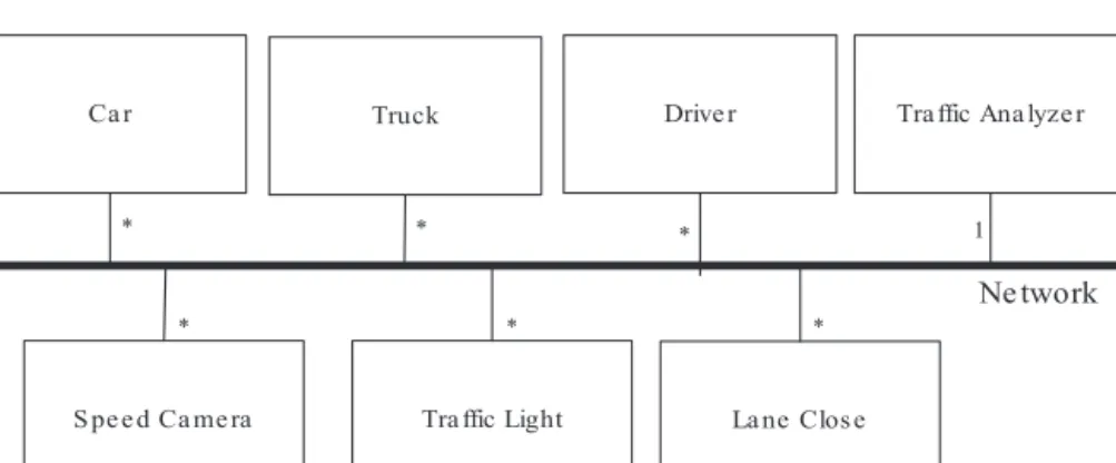
Thecasestudythatweconsideristhedevelopmentofa traf-ficsimulation.Themainobjectiveofthissimulationistosupport theanalysisandoptimizationofvarioustrafficflowparametersfor efficientmovementoftrafficandminimaltrafficcongestion prob-lems.Thelogicalviewforthecasestudythatdepictssimulation environmentisgiveninFig.3.
Themainparticipantsofthesimulationenvironmentarecars, trucks, drivers, speed cameras, traffic lights, lane closes and a traffic analyzer. Other artifacts such as crossings, pedestrians, fixed/mobileradars,on-rampsandweatherconditionsthataffect
Ca r
S pe e d Ca me ra
Drive r
Tra ffic Light
*
*
*
*
Tra ffic Ana lyze r
Ne twork
La ne Clos e * 1 Truck *Table1
Asamplescenarioforthecasestudy.
Simulationmodule Number
Carsimulation 600
Trucksimulation 80
Driversimulation 680
Speedcamerasimulation 5
Trafficlightsimulation 15
Laneclosesimulation 4
Trafficanalyzersimulation 1
thetrafficflowarenotincludedinthecasestudyforthesakeof
simplicity.Inthefigurenoparticularnumberforthesimulation
participantsisgiven,but‘*’isusedtoindicatezeroormore
sim-ulators.Thespecificnumberofsimulatorswillbedefinedbythe
concretescenariowhichwillbeexplainedinthenextsub-section.
Thedefined simulation systemcase study includescars and
trucksasvehicles.Avehiclemodelshallincludepropertiessuchas
modelyear,motorpower,currentdriverid,etc.Drivershave
differ-entphysicalandbehavioralpropertiesthataffectthetrafficflow.
Adrivermodelshallincludepropertiessuchasdriverid,
socio-demographic factors (age, gender, driving experience in years,
etc.),drivingstyle(dissociative,anxious,risky,angry,high-velocity,
distress-reduction,patient,andcareful)(Taubman-Ben-Arietal.,
2004),andaccidentexperiencethatindicateshowmanyaccidents thedriveralreadybeinvolvedinChungandWong(2010).Speed cameras,trafficlights,andlaneclosesareparticipantsthat gener-allyslowdownthetrafficflow.Aspeedcameramodelshalldefine positionand speedlimitvalueparameters.Atrafficlight model shalldefinepositionandlightstate(red,yellow,orgreen).Alane closemodelshalldefineastartposition,anendposition,timeslice thatlaneisclosedandalaneindexthatindicatesclosedlane(like 1stlane,2ndlane).Trafficanalyzerisapassiveparticipantthat col-lectssimulationdatafromotherparticipantssuchasvehiclesand driverstoperformanalysis.
3.2. Asamplescenarioforthetrafficsimulationcasestudy
Afterthedefinitionofthesimulationenvironmentinthecase study section above, we can now define a sample simulation scenario. A scenario includes the types and numbers of major simulationentitiesaccordingtotheearlierdefinedsimulation envi-ronment.Table1showsasamplescenarioforthecasestudy.
The‘SimulationModule’columnofthetableindicatesthe simu-lationparticipantsthattogetherformthesimulationofthesystem. The‘Number’column definesthenumberofsimulation partici-pantsofthe simulationmodule type inthegiven scenario.For example,inthescenarioasdefinedinTable1thereare600carsand 80trucks.Asitcanbeobservedforagivenscenariothetotal num-beroftherequiredsimulationmodulesmightbequitelarge.For thescenariogiveninTable1totalnumberofsimulationmodules is1386.
3.3. Definingtheproblemstatement
After the simulation objectives and a sample scenario are defined,wecanstartdesigningthesimulationsystem.Usingthe referencearchitectureasshowninFig.1andthegivenscenarioin Table1,wecanderivethedeploymentalternative.Adeployment alternativedefinesthemappingofthesimulationmodulesinthe scenariotothenodesandfederates.
Forexample,wecandefineadeploymentalternativewithfour nodesinwhichallcar simulationmodules aredeployedonthe firstnode,alltrucksimulationmodulesaredeployedonthesecond node,alldriversimulationmodulesaredeployedonthethirdnode, andtherestofthesimulationmodulesaredeployedonthefourth
node.Thisalternativeactuallyfollowstheconceptualseparationof concernsinwhichaseparatenodeislogicallydefinedforeach sim-ulationmoduletype.Further,thecommunicationoverheadamong samesimulationmoduletypessuchascars,trucks,etc.are min-imizedbecauseofbeingdeployedonsamenode. Althoughthis alternativeiseasytounderstandbecauseofthelogicalseparation ofconcerns,itdoesnotalwayspay-off.Thisisbecauseseparately deployedsimulationmodulessuchascar,truckanddriver mod-ulesmayneedtointeractveryfrequentlywitheachotherforglobal coordination.
Asecond exampledeployment alternative maycontainonly threenodes. Inthis alternativecar, truckand driversimulation modulesarealldeployedonfirstnode,thespeedcamera,traffic lightandlaneclosemodulesaredeployedonsecondnodewhile trafficanalyzermoduleisdeployedonthirdnodeseparately.This alternativereducesthecommunicationoverheadamongcar,truck anddriversimulationmodulesbydeployingallofthemonthesame node,butontheotherhandthisdeploymentconfigurationmay causeresource(memory,processingpower,etc.)sufferingonthis node.
Wecanderivemanymore differentdeployment alternatives which may differ with respect to the number of deployment nodes,themappingofsimulationmodulestothefederates,etc. Obviously,thenumberofdeploymentalternativesisverylargeand eachdeploymentalternativewillperformdifferentwithrespect todifferentqualityconsiderationssuchaslogical separationfor understandability,optimizingcommunicationoverhead, enhanc-ingutilizationofphysicalresources,etc.
Asstatedbefore,theevaluationofthedesignandthe perfor-manceestimationiseitherdeferredtothedevelopmentphaseor performedbasedonexpertjudgmentinthedesignphase. How-ever,deferringthesedesigntaskstothedevelopmentphasemight leadtonon-feasibleimplementationswhichmayrequire unneces-saryiterationofthedesignandtherelatedprojectlifecycleartifacts suchasdetaileddesign,implementation,testartifacts, documen-tation,etc.Onitsturnthiswillleadtodelaysandhighercostinthe project.Ontheotherhand,expertjudgmentsarealsolimitedifthe systemgetstoocomplex.
In the following section we will provide a tool framework for designing thesimulation environment andderivingfeasible deploymentalternativesforHLAbasedsimulationsystems.
4. Methodforderivingfeasibledeploymentalternatives
Inthissectionweprovidethemethodforderivingand evalu-atingfeasibledeploymentalternativesbrieflybeforedefiningthe designandtheimplementationoftheS-IDEtoolframework.The methodwillbeusedinthedesignphasewherethesystemisnot developedyet,andthecodeisnotavailable.
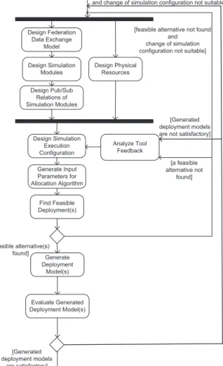
The process flow of the methodis represented as an activ-ity diagram as shown in Fig. 4. Finding a feasible deployment modelmayrequireseveraliterationsofprocesssteps.Further,the finaldeploymentmodelis actuallybuiltonseveraliterationsof thedesign,development,andintegration/testactivitiesdefinedin FEDEP(IEEE,2003).Hereby,theinitialdeploymentmodelis pro-totypedandtestedindevelopmentandintegration/testactivities, andtheresultsarefed backtothedesigneruntil asatisfactory alternativeisderived.Theprocessstepscanbebrieflyexplained asfollows:
1.DesignFederationDataExchangeModel.Thisstepdefinesan ini-tialversion oftheFederation DataExchangeModel (FDEM) thatisnecessarytoenabledataexchangeamongsimulation modules.Actually,aFDEMisanextendedversionofanHLA
DesignSimulation Modules DesignPhysical Resources Design Pub/Sub Relations of Simulation Modules Design Simulation Execution Configuration Generate Input Parameters for Allocation Algorithm Find Feasible Deployment(s) Generate Deployment Model(s) Design Federation Data Exchange Model [feasiblealternative(s) found] [a feasible alternative not found] [feasible alternative not found
and changeofsimulation configurationnotsuitable]
AnalyzeTool Feedback Evaluate Generated Deployment Model(s) [Generated deploymentmodels are satisfactory] [Generated deploymentmodels are not satisfactory] [Generated deployment models are not satisfactory andchangeofsimulationconfigurationnotsuitable]
Fig.4. Methodforderivingfeasibledeploymentalternatives.
FederationObjectModel(FOM)(IEEE,2010c).Detailsofthis extensionrelationwillbeexplainedinSection5.
2.DesignSimulationModules.Thisstepincludesthedefinitionof simulationmodulesthatareartifactsofasimulationsystem responsibleformodelingeachpartofthesystem.Inthegiven examplescenarioasgiveninTable1simulationmodulesare, forexample,Car,Truck,Driver,SpeedCamera,etc.
3.DesignPub/SubRelationsofSimulationModules.Thisstepdefines thepublish/subscriberelationsofsimulationmodulesbasedon theFederationDataExchangeModelwhichisdefinedinfirst stepoftheprocess.Forexample,aCarobjectcanbepublished byCarModuleandsubscribedbySpeedCameraModule. 4.DesignPhysicalResources.Paralleltotheabovethreesteps,this
stepdefinestheavailablenodestogetherwiththeirprocessing power and memory capacity, as well as the network con-nectionsamongthenodes.For example,onemaydecideto adopt4nodesonwhichthesimulationparticipantsneedto bedeployed.Furtheritcouldbedecidedthateachnodehas amemorycapacityof36,840MBandcontainstwoprocessing unitsatthefrequencyof3.0MHz.Equally,thenodescouldalso havedifferentmemorycapacityandprocessingpower. 5.DesignSimulationExecutionConfiguration.Thisstepdefinesthe
run-timepropertiesof themodulesdefined in theprevious steps.Thisincludesthedefinitionofthenumberofsimulation moduleinstances,thedefinitionoftheupdaterateformodule instancesforeachpublication(inthepublish/subscribe defini-tion),andthedefinitionoftheexecutioncostofeachmodule instanceoneachtargetnode.
6.Generate Input Parameters for AllocationAlgorithm.After the stepsabove,boththestaticandrun-timepropertiesofthe sim-ulationparticipants,thesimulationentitiesandthephysical resourcesaredefined,thisstepderivesthenecessary parame-tervaluesforthealgorithmsthatdefineafeasibledeployment alternative.
7.FindFeasibleDeploymentModel(s).Thisactivitytakesthe out-putsofthepreviousactivityasinputparametersandexecutes thealgorithmstocomputefeasibledeploymentalternatives.If afeasibledeploymentisfound,thisactivityyieldsatablethat representsthemappingof tasks(moduleinstances) to pro-cessors(nodes).Itisalsopossibletogeneratemorethanone feasibledeploymentalternativeandpresenttheresultstothe designerfordecidingthedeploymentmodel.
8.AnalyzeToolFeedback.Ifnofeasiblesolutionwasfoundinthe previousstep,detailedfeedbackispresentedtothedesignerto optimizethedesignmodel.Thedesignerwillfirsttrytoupdate thesimulation executionconfiguration.If afeasible deploy-mentcanstillnot befoundthenthedesignercandecideto return tothe beginningof theprocess torefine/update the design.
9.Generate Deployment Model(s). The task-processor mapping tablesthataretheoutputofthepreviousstepwillbeusedin thisstepgenerateoneormoredeploymentmodels.
10.Evaluate Generated Deployment Model(s). In this step, the designerevaluatesthegenerateddeploymentmodelby com-paringitwith:(1)otherdeploymentmodelsgeneratedbythe selectedCTAPalgorithm(2)generatedalternativeswithother CTAPalgorithms(3)manuallygenerateddeploymentmodels withexpertjudgment.TheS-IDEtoolprovidesautomatic analy-sisandcomparisonfeaturesthatenableevaluatingdeployment modelswithrespecttodifferentqualityfactors.Thegenerated deploymentmodelswillbeimproveduntiltheyare consid-eredtobesatisfactorywithrespecttothedefinedgoalsofthe designer.Here asatisfyingalternativedefinesanalternative that meets the expectedimprovement rateof the commu-nicationandexecutioncostsforthedeploymentmodel.Ifa satisfactorysolutionisfound,thefeasibledeployment alterna-tivederivationprocesswillend.Otherwise,thedesignercan generatedesigndiagnosticfeedbackreportwiththeS-IDEtool and analysestheprovided feedback.Thedesigner firsttries tofind a satisfyingdeployment alternativeby updating the simulationexecutionconfiguration.Ifupdatingthesimulation executionconfigurationisnotenoughtoachieveasatisfying deploymentalternative,thedesignercandecidetoreturnto thebeginningoftheprocesstorefine/updatethedesign.
5. Metamodels
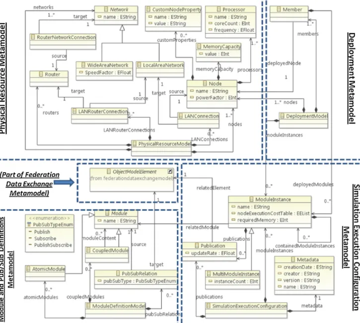
Inthissectionwewilldescribethemetamodelforthemodels thataredefinedinthemethodasshowninFig.4.Themetamodel isshowninFig.5.Asitcanbeseenfromthefigurethemetamodel consistsoffivemainpartsincludingFederationDataExchange, Sim-ulationModulesandPublish/SubscribeDefinitions,PhysicalResources, Simulation Execution Configuration and Deployment metamodels. Weexplaineachofthesemetamodelsinthefollowingsubsection. 5.1. Federationdataexchangemetamodel
TheFederationDataExchangeMetamodelisusedtodescribe Fed-erationDataExchangeModelsinStep1ofthemethoddescribed in Section 4. We have defined this metamodel byreusing and extendingtheHLAOMT(IEEE,2010c)standardwhich definesa standardmetamodelforderivingFederationObjectModels(FOM) andSimulationObjectModels(SOM).TheresultingFederationData
Fig.5.Highlevelviewofthemetamodels.
ExchangeMetamodelcorrespondstotheHLAOMTartifactswith anadditionoftheaveragesizeattributetoarraydatatype.Lateron, thisisnecessarytoallowtheestimationofthesizeofanexchanged objectduringfeasibledeployment analysisatthedesign phase. Sincetheresultedmetamodelisquitelargeinsize,wehaveonly shownthepartofthemetamodelthatrelatestotheotherpartsof ourmetamodelinFig.5.Asitisshowninthefiguretheelement ObjectModelElementisthepartthatdefinestheconnectionwiththe otherpartsofourmetamodel.
Torepresentsimulationentities,HLAOMTspecificationdefines thethreekeyelementsofObjectClasses,InteractionsandDataTypes (notshowninthefigure).ObjectClassesareusedtodefinethe sim-ulationentities.Inourcase,ObjectClassesareusedtorepresent, forexample,Car,Truck,SpeedCamera,etc.Interactionsareusedto representthemessagingsemanticsamongsimulationparticipants. Forexample,messageslikeSpeedLimitViolation,TrafficLightChange areexamplesofinteractions.Finally,DataTypesrepresenttypesof theattributesofObjectClassesandparametersofInteractions.For example,theObjectClassCarcouldhave anattribute positionof typePosition2D,andtheInteractionSpeedLimitViolationcanhave aparametercarIDofStringtype.
5.2. Modulesandpublish/subscriberelationsmetamodel
TheSimulation Modules andPublish/Subscribe Relations Meta-model is used to describe Simulation Modules and Simulation Publish/SubscribeModelsinsteps2and3ofthemethoddescribed inSection4.Wehavedefinedacommonmetamodelthatcanbe usedtodefineboththesimulationmodulesandthecomposition relations.SimilartotheDiscreteEventVirtualSimulation(DEVS) specification (Zeigler, 2003)themetamodel defines atomic and coupledmodelsthatformthesimulationsystems.
AsshowninFig.5,ModuleDefinitionModelrepresentsamodule definitionmodelthatdefinesmodulesandtheirPublish/Subscribe relations. ModuleDefinitionModel contains elements of Atomic-Module, CoupledModule and PubSubRelation. An AtomicModule represents elementary simulation models while CoupledModule represents more complex simulation models that may contain other atomic or coupledmodules. Thiscontainment relation is shown as moduleContent reference in the metamodel. Module is the abstract base class for AtomicModule and CoupledModule definitions.PubSubRelationclassinthemetamodeldefinesa pub-lish/subscriberelationbetweenasimulationmoduleModuleand
FederationDataExchangeModel(FDEM)element ObjectModelEle-ment.
5.3. Physicalresourcesmetamodel
ThePhysicalResourceMetamodelisusedtorepresentthe arti-factsformodelingtheavailablephysicalresourcesinStep4ofthe methoddescribedinSection4.
PhysicalResourceModeldefinesaphysicalresourcemodelwhich canhaveoneormoreNodesthatrepresentcomputationresources. ThepowerFactorattributedefinestheprocessingpowerofthenode relativetoothernodes.Anodecanhaveoneormoreprocessors, memorycapacity,andoneormorecustomnodeproperties. Proces-sordefinespropertiesofaprocessingunitusingtheattributesname, frequencyandcoreCount.MemoryCapacityhasavalueattributethat representsthememorycapacityofthenodeintermsofmegabytes. CustomNodePropertycanbeusedtodefineadditionalpropertiesfor thenodeasname-valuepairs(e.g.diskCapacity–340GB).
Therecanbeoneormorenetworksinaphysicalresourcemodel. TheNetworkclassistheabstractbaseclassforLocalAreaNetwork (LAN)andWideAreaNetwork(WAN)classes.WideAreaNetworkclass hasspeedFactorattribute thatdefines thespeedof thenetwork incomparisonwithaLAN.LANConnectionrepresentsthe connec-tionofanodetoaLAN.Routerrepresentsroutersforconnecting networkswitheachother.LANRouterConnectionclassrepresents connectionofaLANtoarouterwhiletheRouterNetworkConnection classrepresentsconnectionofaroutertoanetwork.
5.4. SimulationExecutionConfigurationMetamodel
The Simulation Execution Configuration Metamodel is usedto definetheartifactstomodelthesimulationexecutionconfiguration inStep5ofthemethoddescribedinSection4. SimulationExecu-tionConfigurationclassdefinesasimulationexecutionconfiguration whichcontainselementsofMetadata,ModuleInstance, MultiMod-uleInstance,andPublication.Metadatadefinesname,version,creator, andcreation dateofa simulation executionconfiguration. Mod-uleInstancerepresentsaninstanceofasimulationmodulethatis definedintheSimulationModulesandPublish/SubscribeRelations Metamodel.
Eachmoduleinstancecanhaveadifferentexecutioncostfor differentnodes.For this ModuleInstanceincludestheparameter nodeExecutionCostTablethatdefinestheexecutioncostvaluesfor thenodesonwhichthemoduleinstancecanexecute.Notethat theexecutioncostisdependentontheselectedexecution configu-ration.Forexample,theexecutioncostofaSpeedCameramodel changes accordingto existing Carsand Trucks inthe execution configuration.Theexecutioncostisascaledvaluethatshowsthe executioncostofaSimulationModuleInstanceincomparisonwith otherSimulationModuleInstancesintheexecutionconfiguration. Forexample,theexecutioncostforeachCarmoduleinstanceis definedusingscaledvalueanddefinedas7over20foronenode, 14over20foranothernode,etc.Theexecutioncostsofsimulation modulesareinfluencedbytheprocessor’spowerFactorand memo-ryCapacityattributes.Inasimilarsense,thecommunicationcosts amongsimulationmodulesareinfluencedbythenetworks speed-Factorattribute.Sincetheexecutionandcommunicationcostsof moduleinstancescanonlybeexactlymeasuredafterthesystemis developed(Lauterbachetal.,2008),duringdesigntimetheirvalues canonlybeestimated.Thisestimationcanbeconductedbyusing, forexample,designphasecomplexitycalculationmethodssuchas proposedbyPodgorelecandHericko(2007),orprototyping.
TheattributerequiredMemoryofModuleInstancerepresentsthe estimatedmemoryamountthatthemoduleinstancewillrequire duringexecution.Similartotheexecutioncost,thisparametercan beestimatedinthedesignphase.TheattributeinstanceCountof
MultiModuleInstancedefinesthenumberofinstancesinthe exe-cutionconfiguration.Thisattributeisaddedbecausetheremaybe multipleinstancesofthesamemoduleinanexecution configu-ration.Forexampleinalargescaletrafficscenario,therecanbe hundredsofCarsanditisnotfeasibletoaddonemoduleinstance foreachofthemtotheexecutionconfigurationseparately.
TherelationcontainedModuleInstancesofModuleInstanceclass showsthemoduleinstancesthatacoupledmodulecontains.The relationrelatedModuleassociatesaModuleInstancewithaModule thatisdefinedintheactivityDesignSimulationModules. ModuleIn-stancecanhavezeroormorePublicationsthatrepresenttheupdate rateandtherelatedelementfromFDEM.Eachpublicationis associ-atedwithanobjectclassattributesetoraninteractionclassdefined inFDEM.
The updateRate attribute shows how many times a module instancewillupdateaFDEMelementinasecond.Forexample, wecoulddecidetohave1000Carmoduleinstanceswhereeachof thempublishesaCarobjectwithupdaterateof2timespersecond. 5.5. DeploymentMetamodel
TheDeploymentMetamodelisusedtodescribethedeployment modelinStep8ofthemethoddescribedinSection4.The deploy-ment Metamodel contains Membersand Nodes. EachMember is deployedononeoftheNodesdefinedinPhysicalResourceModel. OneormoreModuleInstancescanbedeployedonaMember.
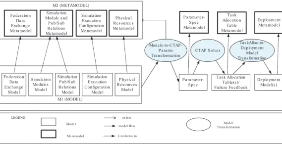
6. Modeltransformations
ThemethodinSection4hasbeenrealizedasasetofmodel trans-formations.ThemodeltransformationchainisshowninFig.6.This modeltransformationchainconsistsofthethreebasic transfor-mationsModels-to-CTAP-ParamsTransformations,CTAPSolver,and TaskAlloc-to-DeploymentModelTransformation.These transforma-tionsaregeneric and donot dependontheuseof aparticular CTAPalgorithm.Weexplainthesetransformationsinthefollowing subsections.
6.1. Manualdesignofsimulationmodels
Theprocessstartswithdefiningthefederationdataexchange model,simulationmodulesandpub-subrelationsmodels,physical resourcesmodel,andsimulation executionconfigurationmodel. These are theoutputs of thefirst five activitiesof the method definedinSection4.Eachofthemodelsconformstotheir corre-spondingmetamodel,whichweredescribedinSection5.
6.2. Models-to-CTAPparameterstransformation
The simulation models are provided to the model trans-formation Models-to-CTAPParams which generates inputs for the“Capacitated TaskAllocation Problem (CTAP)”(Pirim,2006; Mehrabietal.,2009)algorithm.TheCTAPisarefinementofthe taskallocationproblem(TAP) towhichitaddsconstraintssuch asmemorycapacityandprocessingpowertotheproblem formu-lation.TheobjectiveintheCTAPistominimizethesumoftotal executioncostandtotalcommunicationcostamongthesimulation moduleinstances.Hereby,thememorycapacityandtheprocessing powerofeachnodeshouldnotbeexceeded.
Themetamodel for CTAPparameterspecification isgiven in Fig.7.Infact,therequiredparametersofCTAPcanbeextracted fromthesimulation design that hasbeen definedin the previ-ousactivities.InTable2wedescribeeachparameterandhowit isextractedfromthedesign.Theseparametersareindependentof thevariousCTAPalgorithmimplementations.Thetransformation
M M22 ((MMEETTAAMMOODDEELL)) M M11 ((MMOODDEELL)) Fe de ra tion Da ta Excha nge Me ta mode l S imula tion Module a nd P ub/S ub Re la tions Me ta mode l P hys ica l Re s ource s Me ta mode l S imula tion Exe cution Configura tion Me ta mode l Fe de ra tion Da ta Excha nge Mode l S imula tion Module s Mode l S imula tion P ub/S ub Re la tions Mode l S imula tion Exe cution Configura tion Mode l P hys ica l Re s ource s Mode l Mode l Me ta mode l Mode l Tra ns forma tion L
LEEGGEENNDD
Mode ls toCTAP -P a ra ms Tra ns forma tion
CTAP S olve r P a ra me te r-S pe c mode l flow Conforms to re fe rs Ta s kAlloc-to-De ployme nt Mode l Tra ns forma tion
Ta s k Alloca tion Ta ble (s )/ Fa ilure Fe e dba ck De ployme nt Mode l(s ) De ployme nt Me ta mode l P a ra me te r-S pe c Me ta mode l Ta s k Alloca tion Ta ble Me ta mode l
Fig.6. Model-transformationchainthatrealizesthemethodforderivingfeasibledeploymentalternative.
Models-to-CTAP-ParamsTransformationsperformsageneric trans-formationtoextracttheseCTAPparametervaluesthatcanbeused bytheselectedCTAPalgorithmimplementations.
6.3. CTAPsolver
Theinputparametersthatweregeneratedinthepreviousstep areprovidedtotheCTAPSolverwhichaimstofindatask-processor allocation.TheCTAPSolverdoesnotmandatetheuseofa partic-ularCTAPalgorithmimplementation.Wehaveprovidedageneric mechanismtoenabletheselectionandadaptationofdifferentCTAP algorithmimplementationsintheCTAPSolver.Forthis wehave usedtheOSGIserviceregistrycapabilitiesoftheEclipseEquinox platform(McAfferetal.,2010;OSGI,2011; Equinox,2012).The S-IDEtooldefinesagenericserviceinterfaceplug-inthatcanbe realizedbyvarious plug-insto providespecificCTAPalgorithm implementations.TheCTAPSolvermodulequeriestheregistered
CTAPalgorithmimplementationsviaOSGIserviceregistryandas suchenablestheusertoselectoneoftheregisteredalternative algorithms.For detailedinformation onaddingnewCTAP algo-rithmimplementations we refer to theproject web site (SIDE, 2012).
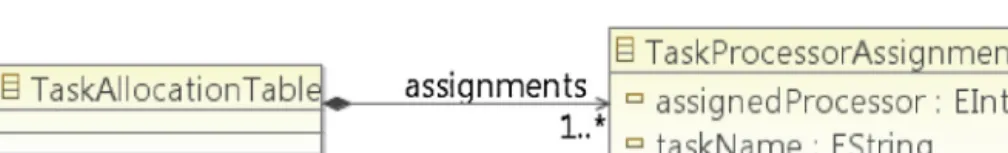
Forourproblem,wefocusonoptimizingtheallocationof sim-ulationmoduleinstancestonodesbyconsideringexecutioncost, memoryrequirement,communicationcost,processingpower,and memorycapacityparametersasdefinedinthesimulationdesign. Pleasenotethat wedo not focusona particularalgorithm but recommendusingapracticaloneforthecorrespondingcase.The outputoftheCTAPSolverisTaskProcessorAllocationTablewhich describesthemappingoftaskstoprocessors.Themetamodelfor TaskProcessorAllocationisgiveninFig.8.
Fordifferentsimulationcontextsthedesignercanchoose dif-ferentCTAPSolverimplementations.Tosupportthedesignerin selectingtheappropriate algorithm implementations, theS-IDE
Table2
ExtractingCTAPparametersfromthedesign.
CTAPparameter Extractionfromdesign
T Setofmtasks.Tasksareextractedfrommodule instancesdefinedinSimulationExecution ConfigurationModel.
P Setofnnon-identicalprocessors.Processorsare extractedfromnodesdefinedinPhysicalResource Model.
Mp Memorycapacityofprocessorp.Memorycapacityis
extractedfrommemoryCapacityattributeofeachnode definedinPhysicalResourceModel.
Cp Processingpowerofprocessorp.Processingpoweris
extractedfrompowerFactorattributeofeachnode definedinPhysicalResourceModel.
mi Amountofmemoryneededfortaski.Amountof
requiredmemoryisextractedfromrequiredMemory attributeofModuleInstancedefinedinSimulation ExecutionConfigurationModel.
xip Processingpowercostofexecutingtaskionprocessor
p.Processingpowercostisextractedfrom nodeExecutionCostTableattributeofModuleInstance definedinSimulationExecutionConfigurationModel. cij Communicationcostcijiftasksiandjareassignedto
differentprocessorscalculatedbyusing:Publications definedinSimulationExecutionConfigurationModel, SubscriptionsdefinedinPublish/SubscribeRelations Model,ObjectmodelelementsdefinedinFederation DataExchangeModelCommunicationcostbetween twonodesisnegligibleiftwotasksareassignedtothe sameprocessor.
toolprovidestheobjectivesand characteristicsofthealgorithm
thataredefinedbythealgorithmdeveloper.
TheCTAPparameterscanbeprioritizediftheselectedCTAP
algorithmsupportssuchaprioritization.Forexample,thegenetic
algorithmbasedCTAPimplementationthatwehaveusedforour
experimentsdefinesthesamecoefficientsforexecutionand
com-municationcosts,thustheparameterprioritiesareequal.However,
as stated before the S-IDE tool doesnot mandatea particular
implementationofthealgorithm,andifneededdifferent
imple-mentationsmightbeselectedthatsupporttheprioritization.The
S-IDEtoolasksthedesignertodefinetheprioritiesiftheselected
CTAPalgorithmsupportstheprioritizationoftheparameters.
6.4. Taskallocation-to-deploymentmodeltransformation
TaskProcessor Allocation Table generated in previous step is
providedasaninputtoTaskAllocation-to-DeploymentModel
Trans-formationthatgeneratesthefinaldeploymentmodels.Incasethe
CTAPSolvercannotfindafeasibletasktoprocessorallocation
alter-nativeorifthealternativeisnotsatisfying,thedesignercanusethe
S-IDEDesignAnalysisToolthatprovidesadetaileddesign
diagnos-ticfeedback.Thedesigndiagnosticfeedbackcontainsthefollowing
information:
• Thecommunicationcostsamongsimulationmoduleinstances
orderedbysizeoftransferreddatapersecond.
• Thesimulationdataexchangemodelobjectsorderedbysize.
• Thesimulationmoduleinstancesorderedbyrequiredamountof
memory.
• Thephysicalresourcesorderedbycapacitylimits.
Thedesignercanusethisdiagnosticfeedbacktoanalyzethe
sim-ulationdesign,updatethemodels,andrestartthetransformation
processagainuntilafeasibleandsatisfyingsolutionisfound.In
gen-eral,distributedsystemsareoptimizedusingdesignheuristicsfor
reducingeitherthecostparametervaluessuchasbandwidthusage
and/orenhancingthecapacitiesoftheadoptedphysicalresources
(Izosimovetal.,2005;WhiteandSchmidt,2010).Basedonthese generaldesignoptimizationheuristicsaswellasourownlessons learnedfromrealindustrialHLAbaseddistributedsimulation sys-tems(C¸eliketal.,2012)andOMGDDSbasedrealtimesystemswe havedefinedthefollowingcategoriesofheuristicrulesthatcanbe appliedinthemethodtooptimizethesystemifafeasibletaskto processorallocationcannotbefound:
1.Simulation Execution Configuration Optimizations.The designer may first try to reduce update rates in the simulation exe-cution configuration. For example, for the given traffic case study,thedesignermaydecidethat trucksareslowvehicles andtheirupdateratesinthesimulationcanbereducedfrom 2updates/secondto1updates/second.
2.SimulationDesignOptimizations:
(a)Ifreducingtheupdateratesinthesimulationexecution configu-rationdoesnothelpfindingafeasiblesolution,thedesignercan re-organizethesubscribeddatasetsandsplitthefederationdata exchangemodelobjectstructures.Inmanycasesthesubscriber onlyrequiresaspecificsetofdataclassattributes(e.g.speedof theobject).
(b)Thedesignermaycheckthereliabilitylevelsofthedataexchange modelelements.InHLA,aFOMobjectcanbesharedamong fed-erateseitherwithReliableor BestEffortreliabilitylevels.The communicationcostofsharingreliabledataishigherthanbest effortsharing.ThereliabilityleveloftheFOMobjectsdefined ReliablecouldbereducedtoBestEffortwherepossibleto fur-theroptimizethesimulationdesign.Forexampleinthetraffic simulationcasestudy,thepositionofthevehiclesisfrequently updatedandcanbedefinedasBestEffort.Insuchacase,the sub-scribersshallusedeadreckoningmethods(Fujimoto,1999)for calculatingthevehiclepositions.
3.PhysicalResourcesModelEnhancements:Ifalldesignlevel opti-mizationsdescribedaboveareappliedanditisstillnotpossible tofindafeasibledeploymentalternative,theonlyalternativeis enhancingthephysicalresources.
Thedesigndiagnosticfeedbackisautomaticallygeneratedifat leastonedeploymentalternativecannotbefound.Thedesigner canalsomanuallytriggerdesigndiagnosticprocessinS-IDEtoolif he/sheisnotsatisfiedwiththequalityofthegenerateddeployment models.Inthiscase,thedesignercanfollowtheheuristicslisted abovetoimprovesimulationdesignuntilasatisfyingdeployment alternativecanbederived.
6.5. Implementationandverificationofthetransformationrules In the above transformations we have basically applied model-to-model transformations in which the transformation
P hys ica l Re s ource s De s ign Tool
Fe de ra tion Da ta Excha nge Mode l De s ign Tool S imula tion Module s a nd P ublis h/S ubs cribe Re la tions
De s ign Tool S imula tion Exe cution Configura tion
De s ign Tool De ployme nt Mode l Ge ne ra tion Tool
Eclips e P la tform EMF GEF GMF E m fa ti c EuGEN ia
Fig.9. LayeredarchitectureofS-IDEenvironment.
rules refer to metamodels of the source and target models. Therearedifferentapproachesforimplementingmodel-to-model transformationsincludingdirectmanipulation,structure-driven, operational,template-based,relationalandgraph transformation-basedandhybridapproaches(CzarneckiandHelsen,2006).We preferredto adopt thedirect model manipulation withEclipse EMFin which aninternal model representation plus some API is provided tomanipulate the models.The advantage of direct manipulation approach is that we could implement complex transformation rules using ouradopted programminglanguage (Java).Likewisewecouldmoreflexiblyimplementthecomplex functionalityofthemodeltransformationssuchascalculating com-municationcostparameters.
Validatingtheimplementedtransformation rulescanalsobe doneindifferentwaysbasedontheselectedmodel transforma-tionapproach(Büttneretal.,2011).Sinceweuseddirectmodel manipulationapproachwecouldverifythecorrectnessoftherules usingunittestingcapabilitiesoftheJavaprogramming environ-ment(JUnit,2012).Wehavetestedeachmodel-transformationunit usingdifferentinputs.
7. S-IDEtoolframework
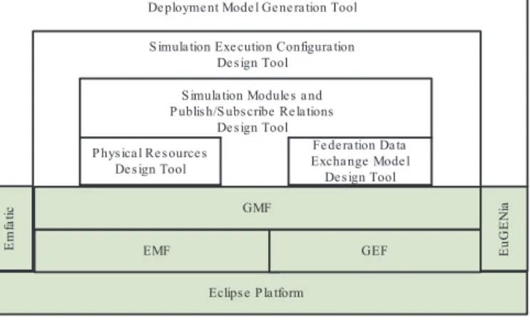
InthissectionwewillpresenttheS-IDEtoolframeworkwhich providesanintegrateddevelopmentenvironmentforsupporting themethodasdefinedinSection4(SIDE,2012).S-IDEtool frame-workis based on themetamodels as defined in Section 5 and themodeltransformationsasdefinedinSection6.S-IDEisbuilt ontheEclipseplatformandisimplementedasasetofplug-ins. Thedevelopedplug-insarebuiltonotherEclipseframework plug-insincludingEclipseModelingFramework(EMF)(Budinskyetal., 2003),GraphicalEditingFramework(GEF)(Mooreetal.,2004),and GraphicalModelingFramework(GMF)(Voelteretal.,2006).EMF isamodelingframeworkandcodegenerationfacilitythatweuse todevelopthemetamodels.GEFisaframeworkthatisusedfor generatingrichgraphicaleditorsandviews.GMFisagenerative componentandruntimeinfrastructurethatweusefordeveloping graphicaleditorsforthedevelopedmetamodels.Further,weuse Emfatic(Daly,2004),whichprovidesatexteditorandalanguage foreditingEMFmodels.InadditionweuseEuGENia(Kolovosetal., 2010)GMFtoolthatprovidesmechanismsfor abstractingaway thecomplexityofGMFandforeasierdevelopmentofGMFeditors. EuGENiatoolisapartofEpsilonproject(Kolovosetal.,2006).The layeredtoolarchitectureoftheS-IDEisgiveninFig.9.
Inthefollowingsubsectionswedescribethetop-leveltool archi-tecture(Section7.1),showtheapplicationofS-IDEfordesigning thesimulationmodelsfortheselectedcasestudy(Section7.2),and
describethegenerationofthedeploymentmodelforthecasestudy (Section7.3).
7.1. Toolarchitecture
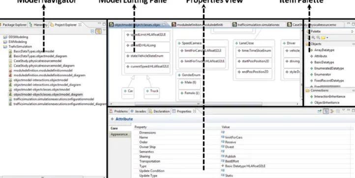
S-IDEconsistsoffivedifferenttools.Thecommonperspective ofS-IDEtoolsisgiveninFig.10.TheleftpaneincludestheModel Navigatorthatshowstheavailablemodelsandtheirelements.The ModelEditingPaneinthemiddleprovidesthemaindrawingarea forthesimulationdesign.TheItemPaletteontherightprovides theobjectsandtheconnectionsthatareusedforcreatingadesign model.TheitemsinthispalettecanbeaddedtotheEditingpaneby dragginganddropping.ThePropertiesViewatthebottomprovides aneditingareafortheattributesofthedesignmodelelementsthat areselectedfromtheEditingPaneortheModelNavigator. 7.2. UsingS-IDEtodesignsimulationmodelsforthecasestudy andderiveafeasibledeployment
InthissectionweusetheS-IDEtodesignthetrafficcasestudy definedinSection3.2andwederiveafeasibledeploymentmodel forthecasestudy.Restofthissectionexplainseachstepofusing S-IDEforthecasestudy.
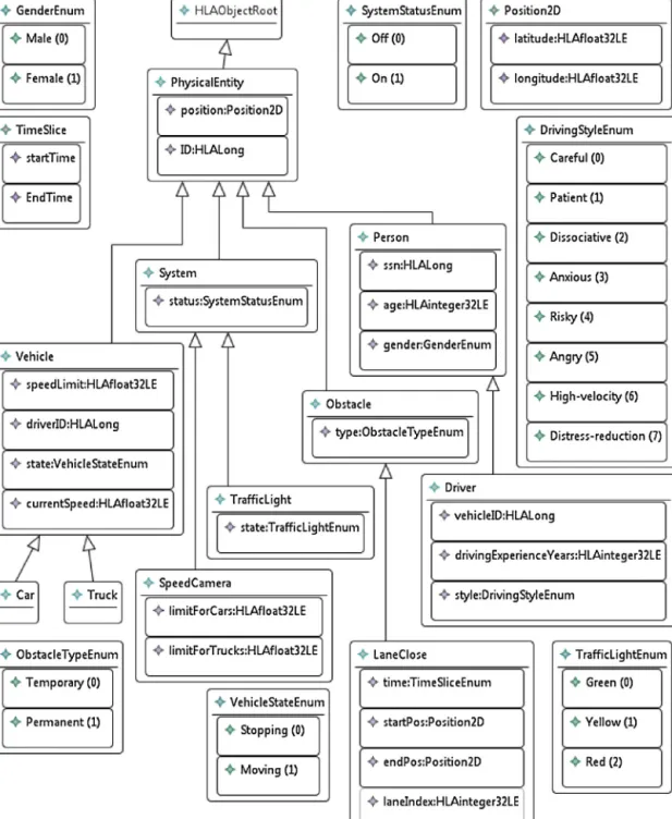
7.2.1. Designingtrafficsimulationfederationdataexchange model
Figs.11and12togethershowTrafficSimulationFederationData ExchangeModel(FDEM)that hasbeendesigned usingtheS-IDE framework.Fig.11definestheobjectclassesofdatamodelwhile Fig.12definestheinteractionclasses.Bothfiguresalsodefinethe necessarydatatypes.
InFig.11,theHLAObjectRootobjectclassisdefinedasrootclass forallotherobjectclassesinconformancewithHLAOMTstandard. PhysicalEntityobjectclassderivesfromtherootclassanddefines twobasicproperties–positionand identification–of aphysical entity.PositionattributeofPhysicalEntityisdefinedbyPosition2D datatypewhichprovideslocationinformationinmeansoflatitude andlongitudevalues.Car,Truck,TrafficLight,SpeedCameraandDriver objectclassesaredefinedinasimilarfashionwithnecessarydata typedefinitionssuchasDrivingStyleEnumenumeratedvaluethat representsdrivingcharacteristicsorTraficLightEnumthatspecifies currentlightstate,oneofRed,Yellow,andGreenvalues.
InFig.12,theHLAInteractionRootinteractionclassisdefinedas rootclassforallotherinteractionclassesinconformancewithHLA OMTstandard.Speedlimitviolations,trafficlightviolationsand accidentsaredefinedasinteractions.Fig.12alsodefinesvarious parameterssuchasviolatingvehicleidorvehicles/pedestriansthat areinvolvedintheaccident.
7.2.2. Designingtrafficsimulationmodulesandpublish/subscribe relations
Fig.13showsthedesignoftrafficsimulationmodulesand pub-lish/subscriberelationsinmeansofTrafficSimulationFederation DataExchangeModeldefinedinpreviousstep.
Asshown in figure,CarModel,TruckModel,DriverModel, Traf-ficLightModel,LaneCloseModel,andSpeedCameraModelsimulation modules defined in according to case study. TrafficAnalyzer simulationmoduledefinedinthecasestudyisrefinedand Driver-Tracker, VehicleTracker, AccidentTracker,and RuleViolationTracker sub-modulesaredefinedasartifactsofTrafficAnalyzermodule.This decompositionmakestheTrafficAnalyzermodulea“coupled mod-ule”thatiscomposedofseveral“atomicmodules”(see“Modules andPublish/SubscribeRelations”metamodelgiveninSection5.2 foratomicandcoupledmoduledefinitions).
Eachmodulepublishestheobjectandinteractionclassesthat they own modeling responsibility (e.g. CarModel publishes Car
Fig.10.GeneralperspectiveofS-IDEtool.
objectclassandAccidentInteractioninteractionclass).Modulesalso subscribe toobjectand interaction classesto receivenecessary updatesofinteresteddata.Forexample,DriverModelsubscribesto TrafficLightandVehicleobjectclassesformodelingbehaviorofthe driver.
7.2.3. Designingphysicalresourcemodel
Fig.14showsanexamplePhysicalResourceModelforthecase, whichhasbeendesignedusingthePhysicalResourceDesignTool. Intheexample,wehavedefined4nodeswithdifferentprocessors andmemorycapacities.Asshowninthefiguresomenodes,like Node-4,canhavemorethanoneprocessor.Although,theexample showsonlyoneLocalAreaNetworkonwhichthenodesare con-nected,thetoolalsoenablesthedesignofheterogeneousLAN/WAN networks.
7.2.4. Designingtrafficsimulationexecutionconfiguration
TheModuleandPublish–SubscribeRelationsModel (Fig.13) andPhysicalResourceModel(Fig.14)areusedintheSimulation ExecutionConfigurationDesignTooltodefinetheSimulation Exe-cutionConfiguration.PartofthelattermodelisshowninFig.15. Here we show an example simulation execution configuration for the scenario as defined in Table 1. The simulation module instances areshown using rectangles.Thenumber of instances for the corresponding module is shown betweenbrackets. For example, in the figure it is indicated that SpeedCameraModel has5instancesinaccordancetotheearlierscenario.Note, how-ever, that in this model the scenario is further refined. More specifically, in Table 1 it is indicated that should be a Traffic Analyzermodule. In the Simulation Execution Configurationin Fig.15,TrafficAnalyzermoduleinstancecontainsfoursub mod-uleinstances(AccidentTrackerModel,VehicleTrackerModel, etc.) justlikeitisdefinedinModuleandPublish–SubscribeRelations Model (Fig. 13).The instances also showthepublication prop-erties (published FDEM element and update rate) as shown in figure.ForexampleCarModelInstance publishesCarobjectclass 2times/second.
7.3. Generatingthedeploymentmodelsforthecasestudy
Sofar,the inputmodels for generatingfeasibledeployment alternativeshavebeendevelopedmanually.Basedonthese mod-els,feasibledeploymentalternativesareautomaticallygenerated. Thetop-levelalgorithmthatisusedfortheautomaticgeneration isshowninFig.16.
As stated in line 1, the algorithm
GENER-ATEFEASIBLEDEPLOYMENTS takes two input parameters: a physical resource modeland a simulation executionconfiguration asdefined, forexample, inFigs. 14and 15,respectively. Line2 extracts processors from the physical resource model by call-ing EXTRACTPROCESSORS in which a processor is created for each node in thephysical resource model. In Line3, tasks are extracted from the simulation execution configuration by call-ing EXTRACTTASKS in which a taskis created for each module instanceandexecutioncostamongtasksiscalculated.InLine4, theactualCTAPalgorithmis executedbycallingEXECUTECTAP. The result of this is stored in assignmenttables that includes a list of assignments of tasks to the processors. Likewise, each memberofassignmenttablesdefinesanabstractspecificationof afeasibledeploymentalternative.InLine5,thedeploymentsare actuallygeneratedbycallingCREATEDEPLOYMENTMODELSwith theparameterassignmenttables.
Asshown inthepseudo code ofFig.16 theCTAPalgorithm cangeneratemultipledeployment alternatives.Twosamplesof deploymentalternativesthataregeneratedbytheCTAPalgorithm areshowninFigs.17and18.Thefiguresrepresentfeasible deploy-mentmodelsforthecasestudyasdescribedinTable1.Asitcanbe observedfromthefigureseachdeploymentmodelincludes4nodes asitwasgiven beforeinthephysicalresourcedefinitionmodel inFig.14.Further,theexecutionconfigurationmodelasdefined in Fig.15hasbeendeployedtothephysicalnodes tooptimize thevaluesforthemetricsexecutioncost,communicationcostand memoryrequirements(seeSection6.2).Asitcanbealsoobserved fromthefigures,thetwodeploymentalternativesinclude differ-entnumberandtypesofdeployedsimulationmoduleinstancesper node.
Fig.11.Federationdataexchangemodel–objectclasses.
8. Evaluation
InthissectionweevaluatetheS-IDEtoolanddiscussthe feasibil-ityofthegenerateddeploymentmodel,andthetimeperformance forgeneratingthedeploymentalternatives.
8.1. Feasibilityofthegenerateddeploymentmodel
Foranalyzingthefeasibilityofthegenerateddeploymentmodel alternativeweusetwodifferentapproaches.
Thefirstapproachisaninformalandpracticalapproachbased on visual inspection of the generated deployment alternative byanexpert.Thisapproach thusrelies ontheassumptionthat an expert can provide logical reasoning about the feasibility of thedeployment alternative. Note that the generationof the
alternativeisdoneautomaticallyandnotperformedbytheexpert. Anexamplereasoningofanexpertcouldbebasedonthe deploy-mentalternativegiveninFig.17.Acloseanalysisofthisgenerated deploymentalternativeshowsthatthetotalresourcerequirements ofsimulationmoduleinstancesdonotexceedthecapacityofthe correspondingnodes.Further,basedontheadoptedgenetic algo-rithm,itappearsthatsimulation moduleinstancesthat interact frequentlyandwhichhavehighcommunicationcosts,areasmuch aspossibleco-locatedonthesamenode.Forexample,the simula-tionmodulesVehicleTracker,CarModel,TruckModelandDriverModel appearedtohavefrequentinteractions inthepublish–subscribe relationsmodel(Fig.13)andinthesimulationexecution configu-ration(Fig.15)wecanobservethattheyhavehighupdate-rates. Likewise,inFig.17theadoptedalgorithmhasco-locatedinstances ofthesemodulesasmuchaspossible.Thesimulationinstancesthat
Fig.12.Federationdataexchangemodel–interactionclasses.
areremainingandwhichwouldexceedthecapacityofNode-1are deployedtoothernodesinasimilarmanner.
Thesecond,moreformalapproachforevaluatingthegenerated deploymentalternative istocomparethegenerated alternative
withanotherdeploymentalternative(Aletietal.,2009a;Malek et al., 2012). The S-IDE tool provides a quality evaluation tool that enables the comparison of two deployment models with respecttogivensimulationexecutionconfigurations.The gener-ateddeployment modelcanbeevaluatedby comparingit with otherdeploymentmodelsasit wasdescribedinSection4,Step 10.
ThecomparisonprocessprovidedintheS-IDEisgenericand canbeappliedinasimilarwayforthealternativesgeneratedwith allthethreeapproaches.Weshowtheevaluationofthegenerated deploymentmodel(Fig.17)withamanuallygenerateddeployment modelthatisbasedonthefirstexampleexpertjudgment deploy-mentmodelgiveninSection3.3(problemstatement).Wehave manuallydefinedthedeploymentmodelfortheexpertjudgment deploymentalternativeinS-IDEenvironment(Fig.19).Asshownin thefigure,allcarsimulationmodulesaredeployedonthefirstnode, alltrucksimulationmodulesaredeployedonthesecondnode,all driversimulationmodulesaredeployedonthethirdnode,andthe restofthesimulationmodulesaredeployedonthefourthnodeas itwasdescribedinSection3.3.
The comparison of theautomatically generated deployment modelalternative(Fig.17)withtheexpertjudgmentdeployment alternative(Fig.19)isgiveninTable3.Thetableshowsthe exe-cutionandcommunicationcostcomparisonsforeachsimulation moduleoftheexpertjudgmentdeploymentalternativeand the generateddeploymentmodelalternative.Theleftcolumnincludes
Fig.14.Asamplephysicalresourcemodelforthecasestudywithfournodes.
themodulesofthedeploymentalternatives.Thetotalnumberof eachentityinthescenarioisshowninparenthesis(e.g. TruckMod-elInstance(×80)meansthatthereare80TruckModuleInstancesin thescenario).ThecolumnExecutionCostdefinesthevaluesfor exe-cutioncostfortheexpertjudgmentandthegeneratedalternative aswellastheimprovementpercentageofthegeneratedalternative overthemanualalternative.Similarly,thecolumnCommunication Costdefinesthevaluesforthecommunicationcostforboth alter-nativemodelsandtheimprovementpercentage.Thelastrowofthe tableshowsthetotalcostsforeachdeploymentalternativeandthe improvementpercentages.
Asshowninthetable,thetotalexecutioncostisoptimizedby 13.63%intheparticularcase.Itisinterestingtoseethatforsomeof
thesimulationmodules(e.g.DriverTrackerModelInstance, Traffic-AnalyzerModelInstance,etc.)theexecutioncostsseemtobebetter intheexpertjudgmentdeploymentalternative.Thisisbecausethe purposeofthedeploymentmodeloptimizationistooptimizethe totalperformanceofthesystem.Forthegivencase,themodules withthetotalhighestexecutioncostappearedtobethemodules DriverModuleInstances,CarModuleInstances,and TruckModuleIn-stanceswithtotalcostof4200,2400and400respectively.Forthese modulestotalimprovementof21.94%,2.88%and1.72%havebeen achieved.Althoughthetotalexecutioncostoftheothermodule instances seemtobeworse,theimpactoftheimprovement of thesethreemodulesseemtodefinethetotalimprovementinthe executioncost.
Table3
Comparinggenerateddeploymentmodelwithmanuallydevelopeddeploymentmodelwithexpertjudgment.
Module Totalexecutioncost Totalcommunicationcost(MB/second)
ExpertJudg. GeneratedbyS-IDE Improv.(%) ExpertJudg. GeneratedbyS-IDE Improv.(%)
DriverTrackerModelInstance(×1) 5.63 11.25 −100.00 0.0 0.0 0.00 TruckModelInstance(×80) 400 393.13 1.72 6.53 4.90 24.97 SpeedCameraModelInstance(×5) 6.25 8.50 −36.00 0.08 0.06 23.79 TrafficAnalyzerModelInstance(×1) 6.25 12.50 −100.00 0.00 0.00 0.00 CarModelInstance(×600) 2400 2331.00 2.88 29.34 22.00 25.03 RuleViolationTrackerModelInstance(×1) 5.63 9.00 −60.00 0.00 0.00 0.00 VehicleTrackerModelInstance(×1) 5.63 9.00 −60.00 0.00 0.00 0.00 AccidentTrackerModelInstance(×1) 6.25 10.00 −60.00 0.00 0.00 0.00 DriverModelInstance(×680) 4250 3317.50 21.94 0.11 0.08 25.59 LaneCloseModelInstance(×4) 7.50 10.50 −40.00 0.10 0.07 24.15 TrafficLightModelInstance(×15) 18.75 30.50 −62.67 0.18 0.13 25.13 Totalcosts 7111.88 6142.88 13.63 36.34 27.25 25.02
Fig.15.Simulationexecutionconfigurationforthecasestudy.
The total communication cost is optimized by 25.02% for
thisparticular case.Againwe canobservethatthedeployment
modelisoptimizedwithrespecttothetotalcommunication
per-formance of the system. As shown in the table, to avoid the
duplication of the communication costs, some of the
simula-tion module instances such as DriverTrackerModelInstance and
TrafficAnalyzerModelInstancearenotchargedanycommunication
costs.For example,theDriverTrackerModelInstancesubscribesto
DriverobjectwhichispublishedbyDriverModelInstanceasgiven
in Fig. 13. The cost of this data exchange is only charged to the publisher (DriverModelInstance) and is not charged to the subscriber (DriverTrackerModelInstance).Since DriverTrackerMod-elInstancedoesnotpublishanyotherobject,nocommunication costischarged.
Wehavealsocarriedoutthesameevaluationforthe automati-callygenerateddeploymentalternativeofFig.18.Theimprovement
Fig.17.Sampleofgeneratedfeasibledeploymentalternative.
ofthetotalexecutioncostwithrespecttothedeploymentmodel definedbytheexpert(Fig.19)is14.30%.Theimprovementofthe communicationcostappearedtobe24.99%.
We have also compared the two automatically generated deploymentalternativesofFigs.17and18.Itappearsthatthe sec-ondalternativeseemstohave 0.78%lowerexecution costwith respecttothefirstalternative.Further,thefirstalternativeseems
tohave0.03%lowercommunicationcost.Basedontheseresults, inthiscaseonewouldslightlypreferthefirstalternativeif opti-mizingthecommunicationcostisconsideredmoreimportantthan optimizingtheexecution cost.Thesecondalternativewouldbe selectedifexecutioncostisconsideredmoreimportant.The evalua-tionofotherdeploymentalternativescanbecarriedoutinasimilar mannertofindthefeasibledeploymentalternative.
Fig.18. Anothersampleofgeneratedfeasibledeploymentalternative.
8.2. Deploymentmodelgenerationperformance
Theperformanceofthedeploymentmodelgenerationprocess islargelyinfluencedbytheperformanceoftheselectedCTAP algo-rithm.Forourparticularcase,theselectedgenerationalgorithm (Mehrabietal.,2009)isimplementedinJavaandexecutedonan IntelCoreI-72.70GHz64-Bitcomputerwith4GBofRAM.Wehave usedtheS-IDEtool toprovidefourdifferentsimulationsofthe
trafficsimulation case study.The resultsof thesimulationsare shown inTable4.In additiontothetrafficsimulation wehave alsodefinedfourdifferentsimulationsintheElectronicWarfare (EW)domain(AdamyandDavid,2006).Eachsimulationhasbeen separatelydefinedandexecuted.Furtherwehavemeasuredthe time to generatethe deployment alternativefor each scenario. Wehavetriedtodefinesimulationswhicharealsorealisticfrom anindustrialperspective.Fromourownindustrialexperiencesin
Fig.19.Expertjudgmentdeploymentalternative.
thedistributed simulationdomainwe canstatethatcasesfrom 4to 12nodes are realistic,whereby 12 nodes is usuallyrarely used.Wehavechosenthesimulationexamplesfrom4to12nodes whichareallrealistic froman industrialperspective.Regarding thenumberofsimulationentitieswehaveusedsimulationswith verylownumberofentities(thelowest17)toveryhighnumber 1596entities.Alsointhiscasetheseexamplesarerealisticinthe industrialsetting.Amediumsizeofarealscenariointhiscontext istypicallya simulationincluding4–6nodeswitharound1000 simulationentities.
FromTable4wecanfurtherobservethatthegenerationtimes ofdeploymentalternativesareacceptableforevaluationatdesign time.Theexecutiontimeofthealgorithmappearstobedependent onthenumberofsimulationentitiesandthenumberofnodes.The higherthenumberofsimulationentitiesthehigherthegeneration timeofthedeploymentalternative.Further,ifthenumberofnodes increasethenfindingafeasibledeploymentalternativewillbe eas-ierandthiswillresultinafastergenerationofthedeployment
alternative.Theseobservationscountforbothcases.However,for thetrafficcasestudythegenerationofthefeasibledeployment alternativestooklongerthanfortheEWsimulationsinthe simu-lationswithlargenumberofsimulationentities.Thisisduetothe differentcommunicationpatternsandexecutioncost characteris-tics.Infactthetrafficcasestudythatwehavedescribediseven morecomplexthanintheEWdomainwithrespectto communi-cationpatternsandexecutioncostcharacteristics.
Asstatedbefore,forthesimulationwehaveusedaparticular implementationoftheCTAPalgorithm.OfcoursedifferentCTAP algorithmimplementationscanleadtodifferentgenerationtimes. TheCTAPalgorithmimplementation(Mehrabietal.,2009)thatwe haveselectedseemstoperformreasonablyfordesigntime deploy-mentalternativegeneration.Afurtheranalysiscouldbeperformed toidentifythebestperformingalgorithm(e.g.Aletietal.,2009a). Theapproachthatwehavepresenteddoesnotmandateaparticular implementationoftheCTAPalgorithm,andweconsiderthe analy-sisofthealgorithmimplementationsbeyondthescopeofthiswork.
Table4
GenerationtimevaluesforscenariosusinganimplementationofCTAPalgorithm.
Simulation no. Simulation Numberof simulationentities Numberof nodes Generation time(s) 1. Trafficsimulation 17 4 2 2. Trafficsimulation 81 4 8 3. Trafficsimulation 1389 4 12,115 4. Trafficsimulation 1389 12 4273 5. EWsimulation 17 4 50 6. EWsimulation 81 4 182 7. EWsimulation 141 5 325 8. EWsimulation 1596 6 360
9. Discussion
Inthisworkwehaveprovidedatoolframeworkforderiving
afeasibledeploymentalternativebasedonthesimulationsystem
andtheavailablephysicalresourcesforHLAbaseddistributed
sim-ulations.The tool frameworkassists thedesignerto designthe
simulationsystemandderiveafeasibledeploymentmodelinearly
systemdesignphase.Thenecessityandpracticalvalueofderiving
afeasibledeploymentmodelinthedesignphaseisbasedonthe
alternativedesignevaluationrelatedrecommendationsdefinedby
theIEEEstandardFEDEP.
Avalidquestioninthiscontextiswhethertheadopted
algo-rithminthetoolframeworkleadstoasolutionandwhetherthis
solutionisoptimal.Wehavedesignedthetoolframeworktoenable
the utilization of different CTAP solver algorithms which have
beenwidelyaddressedintheliterature.Thetoolframeworkdoes
notmandatetheusageofaparticularalgorithmbutprovidesthe
requiredinputparametersforthesealgorithms.Thecorrectnessof
thesealgorithmshasbeendiscussedinthecorrespondingpapers
andbasedonthiswecanassumethatagoodfeasiblesolutioncanbe
derived.Inaddition,dependingonthestateofthesystem,different
CTAPsolveralgorithmsmaybeusedtoderiveafeasibledeployment
alternative.
AsstatedbeforeinSection6.3,theS-IDEtoolcanadopt
differ-entCTAPSolveralgorithmimplementationsthroughOSGIservice registry.Sincedifferentsimulationcontextsmightrequire differ-entCTAPSolverimplementations,theselectionoftheappropriate algorithmimplementationislefttothedesigner’sdecision.To sup-portthedesignerinselectingthealgorithmimplementation,the S-IDEtoolprovidestheobjectivesandcharacteristicsofthe algo-rithmthataredefinedbythealgorithmdeveloper.Ifneeded,the designercanusemultipledifferentalgorithmimplementationsand comparethesimulationresultswiththeS-IDEdesignevaluation tools(seeSection8.1),toselectthemostappropriateone.
WehavealsodefinedgeneralrulestoimprovetheCTAPcost parametervaluestobeabletofindafeasibledeployment alter-nativewithrespect tothe projectrequirements, if theoriginal parametersdonotresultinafeasiblesolution(seeSection6.4). TheS-IDEtoolalsoprovidesdesigndiagnostictoolsthatenablethe analysisofthesimulationdesigntodetectpotentialbottlenecks suchasbigsizeddataexchangeobjects,highcommunicationcosts, limitedphysicalresourcesandhighmemoryrequirementsofthe simulationmodules.
Besidesofthealgorithmicperformance,wealsofocusonthe organizationlevelperformancegain.Existingpracticesusuallybase thegenerationofthedeploymentmodelontheexpertjudgment ordeferthegenerationofthedeploymentmodeltothe imple-mentationphase.Unfortunately,expertjudgmentislimiteddue tothemanualeffort.Wegoonestepfurtherbyintegratingthe existingCTAPsolutiontechniquesearlyinthesystemdesign,and automatethedecision processtosupporttheevaluation ofthe designalternativesbytheexperts.AsstatedbeforeinSection3 (problemstatement),deferringthedefinitionofthedeployment tothedevelopmentphasemightleadtonon-feasible implementa-tionswhichwillrequireiteratingthedesignandtherelatedproject lifecycleartifactssuchasdetaileddesign,implementation,test arti-facts,documentation,etc.Onitsturnthiswillleadtodelaysand highercostintheproject.ThisisalsothereasonwhyFEDEP recom-mendsevaluatingthedesign alternativesintheearlyphasesof thedevelopmentlifecycle.Atdesigntimethevaluesforexecution costandmemoryrequirementsareestimatedwhilethe commu-nicationcostsarecalculated.Obviously,thebettertheestimation the more feasible the derived deployment model will be. The estimationofthevaluescanbeenhancedbyanalyzingexisting sim-ilarmodelsorbydevelopingprototypes.Likewise,theidentified deploymentmodelmayberefinedandoptimizedifmoreaccurate
informationisavailableinsubsequentphasesoftheproject life-cycle.Theapproachitselfcanactuallybeusedatanytimeduring theprojectlifecycleand,ifpossible,evenafterthesystemhas beendeveloped.Inthelattercase,themeasuredrun-time param-etervaluescanbeused,insteadofestimatedvalues,toderivethe deploymentmodel.Theruntimeparametervaluescanbecollected usingHLAManagementObjectModel(MOM)servicesasdefined inIEEE(2010b).
TheS-IDE toolframework canbeusedfordesign level anal-ysis including, the impactof adding new simulations modules tothe system,suitabilityof theselected physical resourcesfor the given simulation design, and the impact of the change of publish–subscriberelations.Toperformsuchanalyses,thedesigner candefinedifferentalternativedesignmodels,generate deploy-mentmodels,andcomparequalityofthegenerateddeployment modelsasdefinedinSection8.1.Assuch,thedesignercanobserve theeffectofdesignvariationsontheperformanceofeach simula-tionmoduleandtheoverallsystem.
The primary goal of our analysis is to findfeasible deploy-mentalternativesgiventhesimulationexecutionconfigurations, whichisbasedonuser-definedscenarios.Wehavechosenforthis approach becausein FEDEPalso firstscenarios aredefined and basedonthesethedesignmodelsarederived.Infacttheoutput ofthetoolframeworkcanbefurtherdetailed,byaddressing,for example,maximumnumberofsimulationmoduleinstancesthat canbe deployedontheavailable physicalresources,theupper boundfortheupdaterateofthesimulationmoduleinstances,the minimumprocessorfrequencyand/ormemorycapacitythatis nec-essaryforthedefinedsimulationmoduleinstances,etc.However, theseanalysiswouldrequireexecutingthecorrespondingCTAP Solveralgorithm manytimeswhichwouldbelesstractableand assuchlesspractical.Thisisbecauseinthesimulationdomainthat wehavefocusedon,thereallifescenarioscancontainthousands ofentitiesanduptodozensofnodes.Nevertheless,ifneededthe designercanexecutethedeploymentmodelgenerationtoolseveral timestofindouttheboundaryvalues.
InthisworktheS-IDEtoolframeworkisusedforderiving fea-sibledeploymentalternativesforHLAbasedsimulationsystems. However,thetoolframeworkcanalsobeadaptedforother archi-tecturesthat adoptpublish–subscribemodel, suchasOMGDDS (OMG,2006)orTENA(Noseworthy,2008).Inthiscase,the meta-modelsandtoolswillbemodifiedforthetargetarchitecture.For example,thedataexchangemodelmayneedtobechangeddueto theparticulardataexchangemodelsforthegiveninfrastructure.In ourfutureresearchwewillanalyzethisinmoredetail.
In the industrial context we have applied our approach to derivefeasibledeploymentalternativesforanElectronicWarfare (EW)simulation.TheEWsimulationscenariosincludearound4–8 nodesandabout1600simulationentities.Wehavedeliberately notchosenthisdomainasarunningexampleinthispaperbecause understandingtheEWcase studyrequiresmoreeffortthanthe moreconceptualdomainoftrafficsimulation.Yet,thesimulations thatwehaveselectedforthetrafficdomainareatleastas com-plexasthatoftheEWsimulationdomain.Inthisrespective,the simulationsthatwehavecarriedarerealistic.Thescalabilityand outputqualityoftheapproachhavebeenanalyzedwithrespect tothenumberandcharacteristicsofsimulationentities,the num-berofnodesandtheadoptedimplementationofthealgorithmin Section8.
10. Relatedwork
Inthispaperwehaveprovidedamodel-drivendevelopment approachforgeneratingandevaluatingdeploymentalternatives forHLA-basedsimulationsystems.Theadoptionofmodel-driven