ISEM2016, 3rd International Symposium on Environment and Morality,
4-6 November 2016, Alanya – Turkey
Determination of the Dam Axis Permeability for the Design and the
Optimization of Grout Curtain: An Example from Orhanlar Dam
(Kütahya-Pazarlar)
*1Mustafa Can Canoğlu and 2Bedri Kurtuluş
*1Sinop University, Faculty of Engineering and Architecture, Environmental Engineering Department, TURKEY 2Muğla Sıtkı Koçman University, Faculty of Engineering, Department of Geological Engineering, TURKEY
Abstract
Rural projects become an important issue considering the rapid increase of population in Turkey. Alongside the contribution to the national economy, dams serve as an environmental structure, which are utilized in flood prevention, sustainable energy, fighting with forest fire and recreation. However, dam construction must be well planned and projected to minimize the unexpected events such as water leakage. This study comprise the geotechnical studies and the design of the planned grout curtain in Orhanlar Dam (Kütahya/Pazarlar). In this context, field and laboratory studies was realized in Orhanlar Dam axis and reservoir area. Within the scope of field studies, engineering geology map was generated, a suitable axis location was specified for the dam and drilling and in-situ testing was realized. Within the field studies, the joint conditions of the geological units under the dam axis and its effect on permeability was observed. For the geotechnical purposes drilling works performed during the planning stage, 5 boreholes total 166 m was realized on dam axis, 1 borehole total 10 m was realized on cofferdam, 1 borehole total 10 m was realized on diversion tunnel and 1 borehole total 10 m was realized on spillway. To determine the permeability profile on dam axis and design the grout curtain, Lugeon tests in Dağardı ophioloitic melange units observed in dam axis, falling head permeability tests in alluviums observed in thalveg and slope debris observed in right abutment were performed. As a result of these studies geotechnical information about the permeability of Orhanlar Dam was collected and the grout curtain hole was designed.
Key words: Orhanlar Dam, Lugeon Tests, Falling head permeability tests, Design and optimization of grout curtain hole.
1. Introduction
In the last decade, dams play an important role contributing to the national economy in terms of potable water supply, agricultural irrigation, recreation and many more. Additionally, environmental benefits of dams such as recreation, fighting with forest fire, sustainable energy, flood protection and swamp draining are not negligible. Due to the difficulty of finding a suitable dam axis location, residential areas in upstream are submerged in order to provide irrigation or water supply of the residential areas, which are located in downstream. Additionally, in some cases, dam construction cause destruction of common areas belong to the village legal entity such as pastures. These areas must be protected due to its environmental importance. To overcome this injustice, finding an optimum axis location that aggrieve nobody is the soil remedy. However, in Orhanlar Dam, this location is unsuitable to construct a dam body due to the permeable ground conditions. Permeable grounds can be remediated with the use of cement grouting technique. To achieve this problem engineering solutions become prominent.
Canoğlu and Kurtuluş / ISEM2016 Alanya – Turkey
Construction of a grout curtain under the dam body is a technique, which is used in several dams all around the world including huge dams such as Atatürk Dam (Turkey), Keban Dam (Turkey), Al Wehdah Dam (Jordan), Douera Dam (Algeria), Berke Dam (Turkey) etc. Dams are studied geotechnically and hydrogeologically by many researchers from different perspectives such as earthquake impact, liquefaction, landsliding (Lombardi, 1985; Nonveiller, 1989; Karagüzel and Kılıç, 2000; Aksoy and Ercanoğlu, 2006; Aksoy and Ercanoğlu, 2007; Ulusay et al., 2007; Gurocak and Alemdağ, 2012; Tunar et al., 2013; Eryılmaz and Korkmaz, 2015; Aldemir et al., 2015).
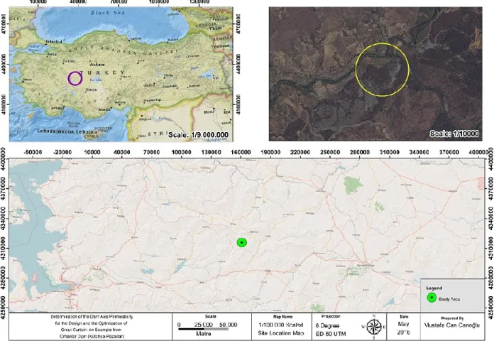
Study area is located in Eagean Region in which the climate has a semi-arid continental climate with hot, dry summers and cold, snowy winters. Water supply to 590 ha of agricultural area, fire fighting in case of a forest fire and recreation are the construction benefit of Orhanlar Dam. The dam and reservoir area is identified in 1/25000 scaled Kütahya K22-a1 topographic map prepared by National Mapping Agency of Turkey. Transport to the dam axis from Küthaya city is accessed by 131.5 km of asphalt and 3.5 km of dusty road (fig.1). In case of excessive rainfall transport to the dam axis location can be failed. For this reason a new access road to the dam axis must be projected for the construction stage.
Figure 1. Location map of study area
The aim of this study is briefly, determination of the hydraulic conductivity characteristics of Kışlademirli Dam axis location and designing grout curtain hole. In this context, optimization of
Canoğlu and Kurtuluş / ISEM2016 Alanya – Turkey
grout curtain hole depths and water income to the excavation pits are specified. Grout curtain hole depth is calculated based on the empirical formula proposed by Şekercioğlu (2007). However the ultimate grout curtain hole depth is determined with the use of engineering judgement considering the hydraulic head on the geological formation.
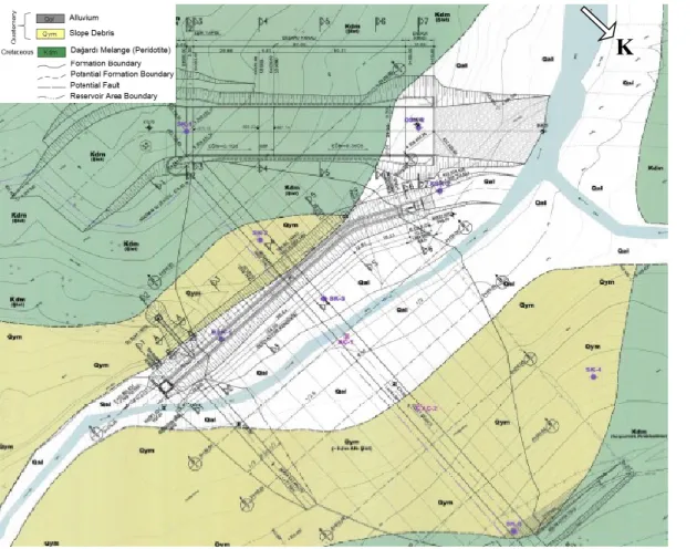
Within this framework, desk studies, field studies and laboratory studies have been performed. Within the desk studies, literature survey is reviewed. Geological mapping, drilling and in situ testing is realized under field studies. Laboratory studies are performed on the samples handled from drilling operation. 1/1000 scaled engineering geology map of axis location is shown on figure 2.
2. Engineering Geology of Study Area
Orhanlar dam body is projected as clay cored rock-filled dam. Its height from thalveg is 29.70 m, height from foundation is 33.20 m. Crest length of dam body is 244 m. Minimum water elevation of reservoir area is 862.95 and maximum water elevation is 876.80 m. Spillway is projected in left abutment with water stilling basin.
5 borehole (total 200 m of depth) is drilled along the dam axis in context of field works. Lugeon (1933) tests were performed in these boreholes in order to determine hydraulic conductivity characteristics of geological units under different hydraulic heads. Hydraulic conductivity of soils is identified by the falling head permeability tests. During the construction stage soils of the dam foundation will be stripped, for this reason calculation of groundwater income into the excavation pit is important.
Geological units in the study area and its near environ pertain to Mesozoic and Cenozoic Eras. The rocks observed are in the range of Cretaceous and Quaternary (Fig. 2). Nethermost Cretaceous aged Dağardı Melange (Kdm) is covered up with lower-middle Miocene aged flysch units (Mç). Quaternary units such as Alluvium (Qal) and Slope Debris (Qym) draw nigh discordantly the older units. Geological map of the study area and its near environ is shown on figure 2.
2.1. Dağardı Melange (Cretaceous)
The geological unit defined as Dağardı melange exposed over large areas in Aegean Region. This unit is investigated by many researchers and aged as Cretaceous. In the study area peridotite type rocks which pertain to Dağardı Melange are observed. According to Bacak and Uz (2003) Neogene units overly Dağardı Melange discordantly. An important leakage problem is not expected regarding the discontinuity orientations and dam axis location based on the field observations. Infilling material material of the discontinuities is generally clay and the mean discontinuity spacing is 3 m.
Canoğlu and Kurtuluş / ISEM2016 Alanya – Turkey
Figure 2. Engineering geology map of Orhanlar Dam
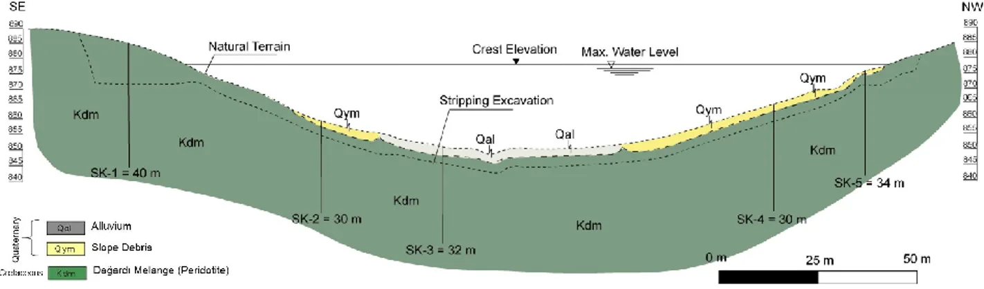
The geological unit defined as Dağardı melange exposed over large areas in Aegean Region. This unit is investigated by many researchers and aged as Cretaceous. In the study area peridotite type rocks which pertain to Dağardı Melange are observed. According to Bacak and Uz (2003) Neogene units overly Dağardı Melange discordantly. An important leakage problem is not expected regarding the discontinuity orientations and dam axis location based on the field observations. Infilling material material of the discontinuities is generally clay and the mean discontinuity spacing is 3 m. The relation between Cretaceous aged Dağardı Melange and Quaternary aged alluviums and slope debris is represented by the cross section (fig. 3).
Canoğlu and Kurtuluş / ISEM2016 Alanya – Turkey
Figure 3. Orhanlar Dam body cross section 2.2 Alluvium (Quaternary)
Quaternary aged alluviums are located along Koyulduk riverbed (figure 2). This unit, which is formed by erosion transportation and deposition, is constituted by gravel, sand, silt and clay sized material. Mean granulometric percentage of the alluvium sampled from the borehole SK-3 is specified as %42 gravel, %62 sand and %6 fine material (clay and silt) based on the laboratory test results. The drilling works shows that the thickness of the alluvium is changed between 4.50 - 5.00 m.
2.3 Slope Debris (Quaternary)
Quaternary aged slope debris are formed by the weathered bedrock and transported to piedmont. (figure 2). This unit, is constituted by gravel, sand, silt and clay sized material. Mean granulometric percentage of the slope debris sampled from the boreholes SK-4 and SK-2 is determined as %15 block, %15 gravel, %20 sand and %50 fine material (clay and silt) based on the laboratory test results. The drilling works shows that the thickness of the slope debris can reach up to 3.50 m.
3. Methodology 3.1. Lugeon tests
Lugeon test is an in-situ test applied in a borehole with the purpose of hydraulic conductivity determination of rock masses under different hydraulic heads. This test is realized generally with test levels changing between 2 – 5 m. Test level length is designate based upon the physical and structural properties of rock mass. In an uniform and impermeable rock mass test level can be applied with 5 – 10 m test zone and in a permeable rock mass which has variable physical properties, this test zone can be reduced until 1 m (Akyüz, 2010). Test method proposed by Lugeon (1933), 1 Lugeon is defined as the water amount pumped to the 1 meter length of test zone under 10 atm hydraulic pressure in 1 minute. The pressure applying to the test zone is also specified by engineering judgement depending on the physical properties of rock but general application in Turkey is using 2, 4, 6, 8, 10 kg/cm2 of test pressures. Each pressure stage applied
to the rock during 10 minutes and the water leakages are recorded each 5 minutes. Then, 9, 7, 5, 3, 1 kg/cm2 of test pressures are applied and water leakages are recorded.
Canoğlu and Kurtuluş / ISEM2016 Alanya – Turkey
Lugeon value is calculated by equation 1.
LU = (Q x 10) / (P x L) (equation 1)
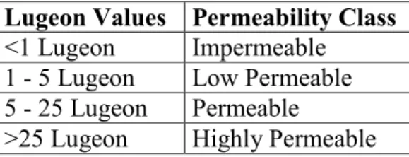
In this expression, LU is Lugeon value (lt/min/m), Q is water amount given to the rock formation (lt/min), P is hydraulic head applied to the test zone (kg/cm2) and L is test length (m). The permeability class corresponding to the Lugeon values is presented in table 1.
Table 1. Permeability classification based on the Lugeon values of rock masses Lugeon Values Permeability Class
<1 Lugeon Impermeable 1 - 5 Lugeon Low Permeable 5 - 25 Lugeon Permeable
>25 Lugeon Highly Permeable
Lugeon test gives important informations in dam projects for the prediction of grout amount injected into the rock mass. For this reason, Lugeon tests have been performed in 5 boreholes drilled on the Orhanlar Dam axis. Minimum, mean and maximum Lugeon values obtained from each boreholes are presented in table 2.
Table 2. Minimum, mean and maximum Lugeon values of each borehole Lugeon Values (LU)
SK-1 SK-2 SK-3 SK-4 SK-5
Minimum 0.18 0.25 0.50 0.30 0.18
Mean 1.90 1.21 2.41 2.35 1.30
Maximum 31.90 6.05 11.94 4.29 3.87
3.2 Design and optimization of grout curtain
A number of method is proposed by many researchers for the determination of grout curtain depth desingn (Bureau of Indian Standard, 1993; Pettersson ve Molin, 1999; Evert, 2003; Şekercioğlu, 2007; Schleiss ve Pougatsch, 2011). Results of these methods are generally close but, in Turkey the method of Şekercioğlu (2007) get in favour as utilized in this study. The calculation of the method proposed by Şekercioğlu (2007) is as follow;
h’ = 2 1 h +15 (equation 2)
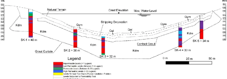
In this equation, h’ represents grout curtain depth, h is height of water on the rock formation. In order to stay in safe side, the same grout curtain depth is utilized in abutments using with engineering judgement. In addition, the grout curtain is extended through the reservoir area for avoiding the potential leakages. The grout curtain design and the permeability profile of Orhanlar Dam axis is presented in figure 4.
Canoğlu and Kurtuluş / ISEM2016 Alanya – Turkey
Figure 4. Orhanlar Dam permeability profile and grout curtain borderline
With the grout curtain shown in figure 4, it is aimed to avoid the potential leakages. The grout curtain depth in left abutment is changing between 28 - 30 m. Augmentation of hydraulic head will increase the hydrostatic pressure on rock formation and trigger the leakages. In this case, maximum hydrostatic pressure will be on thalweg. For this reason, grout curtain depth is augmented (approximately 35 m) coming down to thalweg. For the right abutment, grout curtain depth changes between 25-30 m as well as left abutment.
3.3 Calculation of water income to the excavation pit
Koyulduk river flows during spring season but during summers and autumns river is dry and groundwater flows through quaternary aged alluvium. The groundwater level surveys shows that the phreatic water is changing between 3 m and 4 m. After cut-off excavation on dam axis location, water flux will be oriented through the excavation pit. According to Darcy Law the flow rate will depend on the new hydraulic gradient and the hydraulic conductivity of the alluviums. The falling head permeability tests performed in the alluviums (borehole SK-3) shows that mean hydraulic conductivity is approximately K=10-4cm/s. The water income to the excavation pit can
be estimated by Darcy Law considering the alluviums are homogenous and isotropic (eq. 2). Figure 6 represents a dam body cross section.
Canoğlu and Kurtuluş / ISEM2016 Alanya – Turkey
Figure 5. Schematic representation of dam body and upstream cofferdam (Modified from SuYapı, 2013)
Darcy Formula is Q = A x K x i (equation 2)
In this formula, “Q” is flow rate of water income to the excavation pit, “K” is hydraulic conductivity of alluvium, “A” is section area of the alluvium perpendicular to the flow, “i" is hydraulic gradient, “H” is water height accumulated behind the upstream cofferdam, “h” is water height in the excavation pit and “L” is the horizontal distance between “H” and “h”.
Calculation of water income to the excavation pit is realized based on the following assumptions: 1. Mean alluvium thickness is (based on the geological cross section) = 5.0 m.
2. Mean static level is = 4.0 m.
3. Mean width of the alluvium is = 50.0 m.
4. Hydraulic pressure behind the upstream cofferdam (H2) is assumed as free static
groundwater level
H2 = (Alluvium thickness + Formation) – static groundwater level
H2 = 7.0 – 4.0 = 3.0 m
5. Water amount incoming from rock formation is neglected.
6. Water amount incoming from the upstream excavation wall and downstream excavation wall are assumed as equal.
7. Alluvium is fully saturated under static level.
Considering all these assumptions, water income to the excavation pit is calculated as follow: H1 = Alluvium thickness (5 m) + Formation (2 m) = 7 m
Water income from the upstream excavation wall is; iupstream = (7.0 – 0.0) / 50 = 0.14
Q = (A x K x iupstream) x 2
Q = 800m2 x 10-4 cm/sn x 0.14 x 2
Q ≈ 0.224 lt/sn
Water amount incoming from the upstream excavation wall is calculated as 6.72 lt/min. In this case the total amount of water income to the excavation pit will be approximately 13.44 lt/min. This water must be drained with suitable pumps.
4. Results and Conclusion
By favour of this study, destruction of arable lands and environmentally important areas is avoided by finding a new dam axis location and using grouting techniques for soil remediation.
Canoğlu and Kurtuluş / ISEM2016 Alanya – Turkey
In addition, injustice between the villages located in the upstream of the planned dam axis is averted. In this context, optimization of grout curtain hole depths and water income to the excavation pits are specified considering the universal consent techniques using with engineering judgement. The following results and conclusions can be drawn from the present study.
a) The results handled from the Lugeon tests performed in the boreholes drilled on dam axis are analysed for right abutment, thlaweg and left abutment separately based on the permeability classification presented on table 1.
b) Lugeon tests performed in the boreholes SK-1 and SK-2 drilled for left abutment illustrate that there are some permeable layers in first ten meter but going to deeper low permeable layers are observed. As for thalweg, the borehole SK-3 shows the same permeability character.
c) The permeability profile of right abutment is low permeable for first 15 meter and impermeable after 15 meter as obtained from the boreholes SK-4 and SK-5. But there are some permeable layers for the first 15m fo SK-4.
d) The bedrock of dam axis location belongs to Cretaceous aged Dağardı Melange constituted of peridotites. In addition, 4.5 – 5 m thick of alluvium and 3.5 m thick of slope debris exist in dam axis location. This alluvium and slope debris must be stripped before the construction stage.
e) Water income to the stripping excavation pit is calculated based upon Darcy Law. According this calculation total amount of water income to the excavation pit will be approximately 13.44 lt/min. This water must be discharged out of the excavation pit with suitable pumps.
f) As a result of this study a huge leakage potential is no encountered in dam axis. Small quantity of water leakages from upstream to downstream are planned to restrained by the construction of grout curtain.
g) Considering the strength parameters of bedrock, any stability problem in dam axis is not awaited.
Acknowledgements
This study is realized under the project of “Sakarya: Pamukova-Çilekli, Kemaliye (Deveboynu) and Turgutlu, Central -Beşevler, Kütahya: Pazarlar-Orhanlar, Tavşanlı-Kışlademirli, Bilecik: Söğüt-Savcıbey Dams Planning Engineering Services” realized for Republic Of Turkey Ministry Of Forestry and Water Affairs, General Directorate of State Hydraulic Works, Eskişehir 3. Regional Directorate with the contributions of SUYAPI Engineering Consulting Co.
Author thanks to DSİ 3. Regional Directorate engineer staff and SUYAPI for funding and their experience share.
Canoğlu and Kurtuluş / ISEM2016 Alanya – Turkey
Aksoy, H. and Ercanoğlu, M., 2006. Determination of the rockfall source in an urban settlement area by using a rule-based fuzzy evaluation. Natural Hazards and Earth System Science, 6, 941-954. Aksoy, H. and Ercanoğlu, M., 2007. Fuzzified kinematic analysis of discontinuity-controlled rock slope instabilities. Engineering Geology, 89, 206-219.
Akyüz, S., 2010. Kargı baraj yeri (Çorum) litolojik birimlerin geçirgenlik özellikleri yönünden incelenmesi. Çukurova Üniversitesi, Fen Bilimleri Enstitüsü, Jeoloji Mühendisliği Anabilim Dalı, Yüsek Lisans Tezi, 134s.
Aldemir, A., Yılmaztürk, S.M., Yücel, A.R., Binici, B., Arıcı, Y., Akman, A., 2015. Beton barajların deprem davranışlarının incelenmesinde kullanılan analiz metotları. İMO Teknik Dergi, 6943-6968. Bacak, G., and Uz, B., 2003. Dağardı Güneyi (Tavşanlı-Kütahya) ofiyolitinin jeolojisi ve jeokimyasal özellikleri, İTÜ Dergisi D. Serisi, 86 – 99.
Bureau of Indian Standard, 1993. “Guidelines for the Design of Grout Curtain: Part 2: Masonry and Concrete Gravity Dams”.
Eryılmaz Türkkan, G., Korkmaz, S., 2015. Kuyu ve akifer testlerinde uygulanan analitik ve sayısal yöntemlerle hidrolik iletkenliğin belirlenmesi. İMO Teknik Dergi, 6969-6991.
Ewert, F.K., 2003. Discussion of Rock Type Related Criteria for Curtain Grouting”. Proceedings of the Third International Conference on Grouting in Rock and Ground Improvement, ASCE Special
Publication, No. 120.
Gürocak, Z. ve Alemdağ, S., 2012. Assessment of permeability and injection depth at the Atasu dam site (Turkey) based on experimental and numerical analyses. Bulletin of Engineering Geology and the
Environment, 71, 221-229.
Karagüzel, R. ve Kılıç, R., 2000. The effect of the alteration degree of ophiolitic melange on permeability and grouting. Engineering Geology, 57, 1-12.
Lombardi, G., 1985. The Role of Cohesion in Cement Grouting of Rock, 15. ICOLD-Congress, Lausanne, 3, 235–261.
Lugeon, M. (1933). Barrage et Géologie. Dunod. Paris
Nonveiller, E., 1989. Grouting Theory in Practice. Elsevier, Tokyo.
Pettersson, S.A. and Molin, H., 1999. “Grouting & Drilling for Grouting: Purpose, Application, Methods with Emphasis on Dam and Tunnel Projects”. Atlas Copco. 6991 1019 01
Schleiss, A. J. - Pougatsch, H., 2011. “Les Barrages: Du projet à la mise en service. Presses
Polytechniques Universitaires Romandes, 17, 714p.
Suyapı, 2013. Savcıbey Göleti, mühendislik jeolojisi planlama raporu rev.1. DSİ 3. Bölge Müdürlüğü, Eskişehir.
Şekercioğlu, E., 2007. Yapıların projelendirilmesinde mühendislik jeolojisi. JMO yayınları, 28, 4. Baskı, s.117.
Canoğlu and Kurtuluş / ISEM2016 Alanya – Turkey
Tunar, N.Ö., Ulusay, R., and Işık, N.S., 2013. A study on geotechnical characterization and stability of downstream slope of a tailings dam to improve its storage capacity (Turkey). Environmental Earth
Sciences, 69, 1871-1890.
Ulusay, R., Tuncay, E., and Hasançebi, N., 2007. Liquefaction assessments by filed-based methodologies for the foundation soils at a dam site in northeast Turkey. Bulletin of Engineering