Research Article
Slot Parameter Optimization for Multiband Antenna
Performance Improvement Using Intelligent Systems
Erdem Demircioglu,
1Ahmet Fazil Yagli,
1Senol Gulgonul,
1Haydar Ankishan,
2Emre Oner Tartan,
2Murat H. Sazli,
3and Taha Imeci
41Turksat International Satellite Cable TV Operator, Golbasi, 06380 Ankara, Turkey
2Baskent University, Technical Science MYO, Baglica, 06810 Ankara, Turkey
3Electrics and Electronics Department, Ankara University, Golbasi, 06380 Ankara, Turkey
4Electrical and Electronics Engineering Department, Istanbul Commerce University, Kucukyali, 34840 Istanbul, Turkey
Correspondence should be addressed to Erdem Demircioglu; [email protected] Received 13 August 2015; Revised 28 October 2015; Accepted 2 November 2015
Academic Editor: Ikmo Park
Copyright © 2015 Erdem Demircioglu et al. This is an open access article distributed under the Creative Commons Attribution License, which permits unrestricted use, distribution, and reproduction in any medium, provided the original work is properly cited.
This paper discusses bandwidth enhancement for multiband microstrip patch antennas (MMPAs) using symmetrical rectangu-lar/square slots etched on the patch and the substrate properties. The slot parameters on MMPA are modeled using soft computing technique of artificial neural networks (ANN). To achieve the best ANN performance, Particle Swarm Optimization (PSO) and Differential Evolution (DE) are applied with ANN’s conventional training algorithm in optimization of the modeling performance. In this study, the slot parameters are assumed as slot distance to the radiating patch edge, slot width, and length. Bandwidth enhancement is applied to a formerly designed MMPA fed by a microstrip transmission line attached to the center pin of 50 ohm SMA connecter. The simulated antennas are fabricated and measured. Measurement results are utilized for training the artificial intelligence models. The ANN provides 98% model accuracy for rectangular slots and 97% for square slots; however, ANFIS offer 90% accuracy with lack of resonance frequency tracking.
1. Introduction
Microstrip patch antennas (MPAs) have rapidly develop-ing applications in personal communication systems (PCS), direct broadband television (DBT), mobile satellite com-munication (MSC), wireless local area networks (WLAN), and body area networks (BAN). Low cost and profile with ease of integration to other planar structures, portability, and robustness for implementation on rigid surfaces are well-known advantages of the MPAs [1–4]. Moreover, the MPAs suffer from low gain and efficiency with high loss and narrow bandwidth. Novel antenna designs made effort to overcome these drawbacks by applying various techniques for bandwidth enhancement and multiband radiation.
Single layer multiband antennas can be achieved using reactive loading with stubs [5], monolithic reactive loading [6], adding strips on the patch [7], patch trimming with
a rectangular notch [8], or shorting pins [9] for closely spaced bands with frequency ratios around 1.5 : 1. Multiband printed antennas having frequency band separation of 2 : 1 or 4 : 1 employ window concept whereby windows are cut in low frequency patch radiators to accommodate high frequency patch antennas [10–12]. The other way of realizing multiband antennas needs multilayering with two or more metallic patches between one or more dielectric layers. Dichroic and stacking techniques are commonly used methods with dis-advantages of fabrication complexity and coupling between stacked patches.
Antenna bandwidth is specified as frequency range over which VSWR is less than 2. This offers a return loss of −9.5 dB or 11% reflected power. Typically antenna bandwidth is assumed to be the frequency region providing return loss lower than−10 dB. Bandwidth enhancement for MPAs can be obtained by increasing patch-ground plane separation using
thicker substrate [3]. Thick substrate causes surface wave modes with increasing mutual coupling, degradations in impedance mismatch, radiation loss, polarization distortion, and scan blindness in phased array antennas [13–15]. MPA bandwidth can also be improved by modifying patch shape by slots, adding resonant structures such as more layers, patches, and extra components and applying various feeding techniques such as microstrip line and coaxial, aperture coupled and proximity coupled feeds.
Soft computing based artificial intelligence techniques have broad application areas on microwave design and pro-duction challenges. Bioinspired nature of these techniques allows the microwave equipment designers to avoid repetitive cost of electromagnetic (EM) simulations, manufacturing and test procedures. Artificial neural network (ANN) tech-niques are well-proven methods for microwave design field including antennas [16], arrays [17], MOSFETs [18], passive components [19], and power amplifiers [20].
Particle Swarm Optimization (PSO) is a population based stochastic optimization technique developed by Kennedy and Eberhart in 1995 [21]. It is a global optimization algorithm, which can effectively be used to solve multidimensional opti-mization problems by attempting to simulate the swarming behavior of birds, bees, and so forth. PSO can easily be implemented and its performance is comparable to other stochastic optimization technique, such as genetic algorithm and simulated annealing [22, 23]. PSO integrated with ana-lytical methods or full wave simulation techniques have been widely used to design antennas and arrays [24–30].
Differential Evolution (DE) optimization algorithm is a stochastic vector-based population approach [31]. DE is considered as the fastest optimization method on a general basis over Particle Swarm Optimization and the evolutionary algorithm [32]. Since then, it has found wide applications in engineering designs in various fields [33–37].
In this paper, a slotted MMPA design is proposed. The reference geometry [16] has multiband radiation with limited bandwidth capabilities for the interested frequencies. The multiband property is introduced using inverted L shaped stubs to the main patch. Bandwidth enhancement technique of introducing slots is applied to our previous work where nonslotted antenna geometry provides multiband character-istics at 2.83 GHz, 5.76 GHz, 6.57 GHz, and 11.23 GHz. Slotted antennas obtain broad impedance bandwidth along with stability of the radiation patterns. Variation of the slot shape helps in generating additional resonances, which, when cou-pled to the original resonances of the slot, further increases impedance bandwidths. The antenna gain, radiation pattern, and reflection coefficient are considered as the antenna design constraints. As the symmetrical slots are inserted to the main patch, considerable bandwidth enhancement is explored. However, a generic approach to determine slot parameters is needed. The slot dimensions and distance to the radiating edge are modeled using ANN. Then the ANN architecture is optimized utilizing PSO and DE methods.
In the next section revealing description is given about soft computing based bioinspired modeling techniques and application to proposed problem. In section three, modeling
results are compared with each other and the original non-slotted multiband antenna. Optimization results to determine suitable model architectures are also presented in this chapter. The final section briefly concludes the findings with improve-ments of the proposed methods.
2. Bioinspired Artificial Intelligence Modeling
2.1. Artificial Neural Networks. ANNs are nonlinear soft
computing structures with robust generalization ability from collected data. ANNs have the estimation ability for any input value between its training ranges. This shows its generaliza-tion and memorizing capability. The generalizageneraliza-tion ability makes them applicable to RF microwave modeling field with commonly used multilayer perceptron neural networks (MLPNNs) structure and back-propagation algorithm.
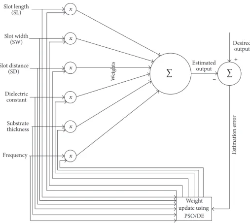
MLPNNs include the input, hidden and output lay-ers with synapses to link laylay-ers. Each layer has the pro-cessing units called neurons to make computations. MLP has been applied successfully to solve diverse problems using supervised training methods with a highly popular algorithm known as the error back-propagation algorithm. Figure 1 represents the proposed MLP network architecture established for the multiresonance antenna slot parameters determination problem.
The physical parameters of antenna slot (slot length/ width and slot distance to radiating edge) are utilized as the ANN model input with substrate features and frequency. The return loss of the slotted antenna is modeled and optimum configuration of the slot parameters is determined. Figure 2 represents the 2D layout of the proposed antenna geometry with physical dimensions in both sides.
A simple quarter wave matching line is attached to the antenna feed line at 5 GHz center frequency of the main patch. Since the feed line alternates only the antenna gain and is utilized to match antenna impedance to the SMA con-nector, its dimensions are not included in the ANN model. Besides the substrate properties slot parameters’ ranges for ANN input parameters vary from 6.57 mm≤ SL ≤ 18.25 mm, 0.75 mm≤ SW ≤ 2.875 mm, and 1.25 mm ≤ SD ≤ 3.75 mm. Both the matching line and the peeled substrate area around proposed antenna are added to the board in order to simplify manufacturing and obtain accurate measurement results.
2.2. Adaptive Network Fuzzy Inference System. ANFIS uses a
hybrid learning algorithm to identify parameters of Sugeno-type fuzzy inference systems. It applies a combination of least-squares and back-propagation gradient descent methods for training fuzzy inference system membership function’s parameters to emulate a given training data set. ANFIS was introduced by Jang in 1993 [38] and it is constructed as a set of fuzzy if-then rules with appropriate membership functions. It specifically has a neurofuzzy type of learning ability with a network having nodes in the five different layers to complete specific functions as shown in the ANFIS architecture in Figure 3.
Slot length (SL) Slot width (SW) Slot distance (SD) Frequency Dielectric constant Substrate thickness x x x x x x Weight update using PSO/DE W eig h ts Estimated output Desired output Es ti m atio n e rr o r + − ∑ ∑
Figure 1: MLPNN architecture for the proposed problem.
77 .4 7 mm 23 .7 49 mm 18.16 1 mm 12.5 73 mm 6. 98 20.066 mm 21.209 mm 9.906 15.367 mm 20.955 mm 26.543 mm mm mm (a) (b)
𝜋 𝜋 𝜋 𝜋 MF 11 MF 12 N N N MF 13 h Inputs Inputs Inputs MF 11 MF 12 MF 13 MF 11 MF 12 MF 13 MF 11 MF 12 MF 13 MF 11 MF 12 MF 13 MF 11 MF 12 MF 13 SL SW SD Scattering parameters 𝜀r fr W1 Wn Wm S1 Sn Sm S1F1 SnFn SmFm ... ... ... ... ... ... ... ∑
Figure 3: Sugeno-type adaptive neurofuzzy system.
Two fuzzy if-then rules based on a first-order Sugeno model with inputs𝑥 and 𝑦 are equated as follows.
Rule 1 if (𝑥 is 𝐴1) and (𝑦 is 𝐵1) then (𝑓1= 𝑝1𝑥 + 𝑞1𝑦 + 𝑟1) . (1) Rule 2 if (𝑥 is 𝐴2) and (𝑦 is 𝐵2) then (𝑓2= 𝑝2𝑥 + 𝑞2𝑦 + 𝑟2) . (2) 𝐴𝑖 and𝐵𝑖 are fuzzy sets,𝑓𝑖is outputs within the fuzzy region specified by the rules, and𝑝𝑖,𝑞𝑖, and𝑟𝑖are the design parameters that are determined during the training process.
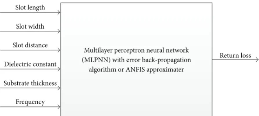
The black box model of the proposed antenna is given in Figure 4 for MLPNN and ANFIS approximates. Initially input(s) and output(s) parameters of the black box are defined; then data sets are generated with full ranges of input parameters using measurements and simulations. Once the measurement data is applied for ANN/ANFIS modeling, trained model should estimate accurate results and iteration
of test and measurement steps can be reduced which lead to the manufacturing cost at a minimum level.
3. Optimization of Modeling Architecture
A multilayer feedforward perceptron ANN consists of inter-connected neurons over consecutive layers. The neuron output is scaled by a weight and fed forward as an input through a nonlinear activation function to the succeed-ing layer neurons. This structure leads to a trained ANN performing nonlinear mapping between input and output vectors. The training process is based on updating the weights according to the error between input and output data in every epoch. Despite the common use of the back-propagation (BP) algorithm for the training, its vital drawback is the local optima problem. This may be encountered due to the gradient based method. Since the BP depends on gradient based method, the random initialization of weights may lead to missing global optima and getting stuck in local optima. As the dimension order is high and the problem is com-plex, search space can contain many local optimum points. Conversely metaheuristic algorithms avoid this problem byMultilayer perceptron neural network (MLPNN) with error back-propagation
algorithm or ANFIS approximater Slot width Slot distance Dielectric constant Substrate thickness Frequency Return loss
Figure 4: Black box representation of ANN/ANFIS approximates.
providing diversity for potential solutions in search space. Therefore, instead of BP, regarding global search capabilities, evolutionary computation algorithms are applied for ANN training. In this study, local optima problem is tested using two evolutionary computation algorithms, Particle Swarm Optimization (PSO) and Differential Evolution (DE).
3.1. Differential Evolution (DE). Differential Evolution (DE)
is an evolutionary optimization algorithm introduced by Storn and Pricer [31]. DE has been applied in many real world problems as well as benchmark functions. DE has a simple yet efficient algorithm which makes it suitable for global optimization problems. Basically the algorithm is based on diversifying the population according to the scaled vector differences and updating next generation using greedy scheme.
The algorithm can be given in four steps.
Initialization. In DE, the population that contains potential
solutions is named target population represented by𝑋. 𝑖th member of 𝑋 is a target vector 𝑥𝑖. 𝑁𝑝 target vectors are initialized in search space randomly as follows:
𝑥𝑗,𝑖= 𝑏𝑗,𝑙+ rand𝑗⋅ (𝑏𝑗,𝑢− 𝑏𝑗,𝑙) , (3) where𝑏𝑗,𝑢is the upper bound and𝑏𝑗,𝑙is lower bound of search space, respectively.𝑗 = 1, 2, . . . , 𝐷 represents the dimension number of the vector𝑥𝑖and rand𝑗is random number between 0 and 1.
Mutation. DE applies two operators for population diversity.
Firstly, mutation operator is applied to obtain a mutant vector V𝑖to be used in the later crossover stage. There are several DE variants represented as DE/𝑥/𝑦/𝑧. In this representation 𝑥 denotes the base vector, 𝑦 denotes the number of difference vectors used, and 𝑧 represents the crossover method. In classic variant of DE, represented as DE/rand/1/bin, mutant vector is obtained as
V𝑖= 𝑥𝑟0+ 𝐹 ⋅ (𝑥𝑟1− 𝑥𝑟2) . (4) In classic variant of DE, represented as DE/rand/1/bin, mutant vector is obtained as
V𝑖,𝑔 = 𝑥𝑟0,𝑔+ 𝐹 ⋅ (𝑥𝑟1,𝑔− 𝑥𝑟2,𝑔) , (5)
where𝑟0,𝑟1, and𝑟2are randomly chosen distinct indexes and different from target index𝑖. the scale factor, 𝐹 ∈ (0, 1+), is a positive number generally selected smaller than 1. In this study for the purpose of fast convergence we adopt DE/best/1/bin version which uses the best vector as the base vector. Then the mutant vector is given as
V𝑖,𝑔 = 𝑥best,𝑔+ 𝐹 ⋅ (𝑥𝑟1,𝑔− 𝑥𝑟2,𝑔) . (6)
Crossover. In crossover, the mutant vector and the target
vector are recombined to produce a trial vector 𝑢𝑖 that is a candidate for new target vector. The parameters at 𝑗th dimension of two vectors are mixed, according to a random number rand𝑗 between 0 and 1. If rand𝑗 is smaller or equal to the predetermined crossover probability 𝐶𝑟, parameter of trial vector takes the𝑗th parameter from mutant vector; otherwise, target vector’s parameter is taken. To ensure that there is at least one parameter different from target vector, the dimension that is equal to a random index number rand𝑗 is changed as mutant:
𝑢𝑖,𝑗={{ {
V𝑗; if (rand𝑗 ≤ 𝐶𝑟 or𝑗 = 𝑗rand)
𝑥𝑗; otherwise, (7)
where𝑢𝑖is the trial vector.
Selection. Selection is carried out by a simple greedy scheme
that compares the objective function values of target and trial vectors. The vector that has a better objective function value takes place in the next generation as target vector.
By repeating this loop for every target vector, a generation is completed and the population is updated.
3.2. Particle Swarm Optimization (PSO). The Particle Swarm
Optimization (PSO) is an evolutionary computation algo-rithm inspired by social behavior of bird flocking and fish schooling. As a population based algorithm like other evolutionary algorithms, PSO updates its members using a predefined fitness function. In the search process PSO mimics the inspired swarm behavior according to fitness function to update the population. In PSO each member named particle 𝑥𝑖keeps track of the overall best position and its best position
Table 1: Fabricated rectangular slotted antenna properties. Prototype name Slot length Slot width Slot distance
Prototype A 730 30 100
Prototype B 545 85 100
Prototype C 545 115 100
Prototype D 545 40 75
in hyperspace. Each particle tends to its best position𝑝𝑖and the population’s best position𝑔𝑖achieved thus far. These are called local best and global best, respectively. In the position update a velocity termV𝑖 is added to the particle’s present position𝑥𝑖. The velocity includes the particle’s previous scaled velocity and the movements towards local and global best positions. The velocity and position updates are given as follows:
V𝑖= 𝑤 ∗ V𝑖+ 𝑐1∗ rand1∗(𝑝𝑔− 𝑥𝑖) + 𝑐2∗ rand2
∗(𝑝𝑖− 𝑥𝑖) , (8)
𝑥𝑖= 𝑥𝑖+ V𝑖. (9)
In (8)𝑐1and𝑐2are acceleration constants that determine the rate of movements towards local best and global best. Rand1and rand2are random numbers between 0 and 1, which are used to diversify movement directions.𝑤 is the inertia weight that helps to improve convergence by scaling previous velocity. Here the adopted variable weight,𝑤, is initialized as 0.9 and decreased to 0.4 at the end of maximum generations.
4. Modeling and Optimization Results
The proposed antennas are designed with various Rogers Duroid substrates using method of moments based AWR AXIEM solver. Selected samples (RT/duroid 5880 with𝜀𝑟 = 2.2 and substrate thickness of 0.775 mm) are fabricated using LPFK milling machine and measured with Agilent E5071C ENA series network analyzer. The bandwidth enhancement can be achieved by increasing substrate thickness or intro-ducing slots into the main patch. The slot parameters, dis-tance to radiating edges, width, and length are manipulated to attain the optimum antenna geometry.
Frequency, dielectric constant, and substrate thickness are also taken as the input parameters since they directly affect antenna characteristics. In this study, the substrate thickness varies from 0.775 mm to 3.125 mm, the dielectric constant, 𝜀𝑟, is taken as 2.2 or 2.94, and the measurement frequency range alters from 1 GHz to 15 GHz.
4.1. Modeling Results. Symmetrical rectangular dual slots are
applied with altering distances to radiating patches between 1.25 and 3.75 mm. Slot lengths and widths are varied from 6.75 to 18.25 mm and 0.75 to 2.875 mm, respectively. Above all simulations, 4 slotted prototypes are fabricated to gather measurement data. The fabricated prototype antenna param-eters are given in Table 1.
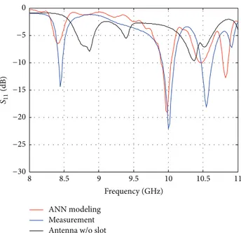
Simulated and measured results for slotted antennas are illustrated with nonslotted multiband antenna to compare
ANN modeling Measurement Antenna w/o slot
S11 (dB) −30 −25 −20 −15 −10 −5 0 8.5 9 9.5 10 10.5 11 8 Frequency (GHz)
Figure 5: Bandwidth and resonance enhancement for 8 GHz to 11 GHz range of Prototype B.
ANN modeling EM simulation Antenna w/o slots
S11 (dB) −30 −25 −20 −15 −10 −5 0 8.5 9 9.5 10 10.5 11 8 Frequency (GHz)
Figure 6: Bandwidth enhancement for 8 GHz to 11 GHz range by thickening substrate.
the bandwidth enhancement and resonance characteristics. The optimum slot parameters (length, width, and distance values) and substrate selection are determined using artificial intelligence techniques. In Figure 5, the frequency band of 8 GHz to 11 GHz of Prototype B is given. The bandwidth and resonance enhancements can be observed compared to nonslotted antenna among frequency range with slight center frequency shifts.
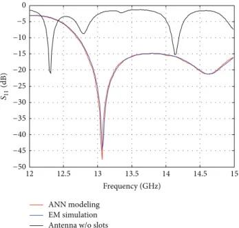
In Figures 6 and 7, slot and substrate thickness impacts on 8 GHz–11 GHz and 12 GHz–15 GHz frequency ranges are illustrated, respectively. Thickening the antenna substrate is
ANN modeling EM simulation Antenna w/o slots
S11 (dB) −50 −45 −40 −35 −30 −25 −20 −15 −10 −5 12.5 13 13.5 14 14.5 15 12 Frequency (GHz)
Figure 7: Bandwidth enhancement for 12 GHz to 15 GHz range by thickening substrate. z y Theta Type Approximation Monitor Component Output Frequency Red. effic. Tot. effic. Gain Far field Enabled (kR ≫ 1) Far field (f = 6.15) [1] Abs Gain 6.15 7.268 dB −32.7 −28.6 −24.5 −20.5 −16.4 −12.3 −8.18 −4.09 0 0.909 1.82 2.73 3.63 5.45 4.54 6.36 7.27 (dB) −2.082 dB −1.623 dB
Figure 8: Radiation pattern of Prototype B at 6.15 GHz.
a very well-known technique to improve antenna resonance bandwidth. Besides introducing slots, substrate properties are investigated to improve overall antenna performance. A 3.125 mm thick substrate is applied in order to investigate antenna performance using AWR AXIEM simulator. As seen in Figure 6, center frequency shifts for 8–11 GHz range are considerably limited; however, resonance values improved significantly over a wide range of frequency.
The resonance bandwidth characteristic is improved suf-ficiently for the frequency band over 13.06 GHz as shown in Figure 7.
The antenna patterns are also examined in order to detect effective radiation characteristics in resonance frequency points. Figure 8 depicts the radiation pattern of Prototype B achieving satisfactory antenna gain for multiband applica-tion. JX Y magni tude (Am p s/m) 0.00 0.62 1.23 1.85 2.46 3.08 3.69 4.31 4.92 5.54 6.15 6.77 7.38
Figure 9: Radiation pattern of Prototype B at 6.15 GHz.
Figure 10: Multiband antenna with 6 symmetrical square slots.
Other than gain, currents on the antenna surface are analyzed for each prototype. Figure 9 illustrates the surface current of the proposed antenna at 6.15 GHz. Antenna has single radiation point with the main patch. As the inverted L stubs are introduced multiband characterization is observed. Prototype B radiates from the second and third stubs at 6.15 GHz since other stubs and main patch have low surface current.
In addition to rectangular slots, square slots are intro-duced to achieve bandwidth enhancement. Figure 10 shows the manufactured antenna with 6 square slots of 3 mm slot edge dimensions. Slot distance to radiating patch is fixed by 2.5 mm.
In Figure 11 ANN and ANFIS modeling results are com-pared with slotted antenna measurements. Bandwidth en-hancement is achieved at higher frequencies around 10 GHz by introducing square slots compared to original nonslotted antenna. An optimum square slot dimension is determined as 3 mm. It is observed from the antenna spectrum that radiation points diminish and bandwidths shrink while the square slot dimensions are getting larger.
In Table 2, nonslotted antenna and the slotted antenna with thick substrate are compared with antenna performance parameters of bandwidth, resonance frequency, and gain.
4.2. Optimization Results. In this paper, two population
based evolutionary optimization algorithms were used to optimize the ANN parameters of the proposed system. Here, DE and PSO parameters were firstly tuned and the experimental results have been compared with derivative
ANN modeling Measurement ANFIS modeling −20 −18 −16 −14 −12 −10 −8 −6 −4 −2 0 Ret u rn los s 9 9.2 9.4 9.6 9.8 10 10.2 10.4 10.6 10.8 Frequency
Figure 11: Modeling performance comparison of RT/d 5880 multi-band antenna with 3× 3 mm symmetrical square slots.
Table 2: Comparison of performance parameters for nonslotted and slotted antennas.
Nonslotted antenna Slotted antenna Center frequency (GHz) 4.15 Center frequency (GHz) 4.657 Bandwidth (MHz) 20 Bandwidth (MHz) 260
Gain (dB) 6.91 Gain (dB) 6
Center frequency (GHz) 5.85 Center frequency (GHz) 5.77 Bandwidth (MHz) 50 Bandwidth (MHz) 230 Gain (dB) 8.97 Gain (dB) 8.994 Center frequency (GHz) 11.3 Center frequency (GHz) 10.3 Bandwidth (MHz) 90 Bandwidth (MHz) 925 Gain (dB) 11.44 Gain (dB) 7.76 Center frequency (GHz) 14.95 Center frequency (GHz) 14.6 Bandwidth (MHz) 110 Bandwidth (MHz) 800 Gain (dB) 10.95 Gain (dB) 8.51
based ANN training algorithm. Figure 12 represents the com-parison of EM circuit design including traditional method, DE/PSO based design method, and proposed optimization method.
For PSO, three variants have been applied and the best variant’s result is given with DE and Back-Propagation Method’s results in Table 3.
ANN Training. In this application, an ANN model with two
hidden layers is considered. Model with 𝑘 inputs and 𝑧 outputs, consisting of𝑚1 and 𝑚2 neurons, in the first and second hidden layers, respectively, has𝑘⋅𝑚1+𝑚1⋅𝑚2+𝑚2⋅𝑧 weights and𝑚1+ 𝑚2+ 𝑧 thresholds. Therefore, total number of parameters of network will be𝐷 = 𝑘 ⋅ 𝑚1+ 𝑚1⋅ 𝑚2+ 𝑚2⋅ 𝑧+𝑚1+𝑚2+𝑧 and search space in optimization problem will
have𝐷 dimensions.
Table 3: Comparison of performance results for applied artificial intelligence methods.
ANN DE CPSO ANFIS
Average 8.136 11.535 11.1353 11.09 Best 7.3243 10.3840 9.9730 9.9328
Mean square error can be used as fitness function to evaluate a member’s fitness in the algorithms. The hidden transfer function is sigmoid function and the output transfer is a linear activation function; then the fitness function of the 𝑖th member of population is derived as follows:
𝑓 (𝑠𝑗) = 1 (1 + exp (− (∑𝑛𝑖=1𝑤𝑖𝑗⋅ 𝑥𝑖− 𝜃𝑗))), 𝑦𝑘= 𝑇 ∑ 𝑗=1𝑤𝑘𝑗⋅ 𝑓 (𝑠𝑗) − 𝜃𝑘, 𝐸 =∑𝑞 𝑘=1 𝐸𝑘 (𝑞 ∗𝑀), 𝐸𝑘=∑𝑀 𝑖=0 (error𝑘𝑖) , fitness(𝑋𝑖) = 𝐸 (𝑋𝑖) , (10)
where𝑛 is the number of input nodes, 𝑤𝑖𝑗is the weight from 𝑖th node of input layer to 𝑗th node of the hidden layer, 𝜃𝑗 is the threshold of the𝑗th hidden layer, 𝑥𝑖is the𝑖th input, 𝑠𝑗is the weight input sum in hidden layer,𝑦𝑘is the output of𝑘th layer,𝑞 is the number of training samples, 𝐸 is the training error,𝑗 = 1, 2, . . . , 𝑇, and 𝑘 = 1, 2, . . . , 𝑀.
Differential Evolution (DE) Training. As explained above,
DE needs two parameters in population diversity operators. These are scale factor𝐹 and crossover probability 𝐶𝑟. These parameters can be tuned according to the optimization problem. Firstly we investigate the suitable𝐹, 𝐶𝑟 pair and then use the best pair in the final training procedure. Since both parameters are in the same interval, they can be tested by increment of 0.1 from 0.1 to 1. Incrementing𝐹 by 0.1 from 0.1 to 1, meanwhile fixing the 𝐶𝑟 and repeating this cycle after each increment of 𝐶𝑟 by 0.1 will yield 100 pairs. The performances of networks trained according to these pairs are given in Figure 10 where a set of pairs yield close test errors. Among these pairs the best performance is obtained by𝐹 = 0.4 and 𝐶𝑟= 0.9. Using these values network is trained for 10 times. The average performance of network is obtained as 11.535 where the best performance was 11.0341. Figure 13 depicts the scale factor versus crossover probability of DE.
Particle Swarm Optimization Training. Each PSOPC is run for
10 times,𝐺max = 1000, and an average performance value is recorded. First, a standard PSO with inertia weight is applied and acceleration constants are set as 2. Then a decaying inertia weight𝜔 is adopted as proposed in [39]. 𝜔 is initialized to 0.9
EM simulator Device fabrication Test and measurement (a) EM simulation Fitness function DE/PSO (b) EM simulation Fitness function Measurement
data for training
ANN model
DE/PSO
(c)
Figure 12: (a) Traditional design method using expert domain knowledge and hit/trial method. (b) Design using DE/PSO by directly appealing EM simulator as its fitness function. (c) Design using proposed method of ANN optimization with DE/PSO.
0 2 4 6 8 10 0 2 4 6 8 10 10 12 14 16 18 20 F (scale fac tor) Cr(crossover p robability)
Figure 13: Scale factor versus crossover probability of DE.
and reduced to 0.4 at the final stage. Average performance value is obtained as 13.7989.
Secondly, the acceleration constants are set as 0.5, and passive congregation coefficient is set as 0.6 [40]. Inertia weight is initialized as 0.9 and decreased to 0.7 at the end. The average performance is 11.3670. Finally, CPSO is applied for the calculation of constriction factor using Clerc’s method. Acceleration constants𝑐1 and 𝑐2 are set as 2.05, 𝜑 is set to 4.1, and constriction factor is given as 𝜒 = 0.729 by [41]. The average performance value was 11.1353. It is observed that among three variants the best average performance is obtained by CPSO. Therefore, best result obtained by CPSO is used for the training of ANN and comparison with other methods.
For the training of the ANN three different methods have been applied in order to obtain the best performance and check local optimality problem. The average and best error values of the ANNs are given in Table 2. As seen from the table among these algorithms, the best result is obtained by
the conventional back-propagation algorithm. Therefore, the methods with the best performance have been used to train ANN that has been used to determine optimum antenna shape.
5. Conclusion
Multiband microstrip patch antennas have wide application areas in mobile technology such as GSM, UMTS, LTE, and Bluetooth. However, it is complicated for antenna designers to attain multiband antenna characteristics with enhanced communication bandwidth. Multiband characteristic of the antenna disappears as bandwidth enhancement is applied. In this study, rectangular and square slots are introduced into MMPAs to overcome bandwidth problem. Return loss is determined as the antenna performance parameter and set to the modeling output. Slot dimensions and distance to antenna edge are varied to find optimum slot configuration providing multiple bands and enhanced bandwidth.
The comparisons for variations of slot parameters indicate that, as the slot width increases, antenna return loss lessens and reflections are reduced noticeably. Slot width variations cause slight center frequency oscillations without band-width enhancement. Also slot distance to radiating edges is inspected. It is shown that closer slots to radiating patch edge introduce more resonance at lower frequencies. The mean slot distance results are more beneficial in terms of bandwidth enhancement and resonance points compared to far and near ones. Moreover, slot length alternations with fixed slot width and distance are examined. Multiple radiation points and higher bandwidth performances are achieved with an average slot length. Increasing slot length causes disappearance of radiation at lowest frequencies.
The proposed modeling techniques utilize bioinspired artificial intelligence methods to determine optimum an-tenna shape. Artificial modeling techniques prevent iter-ative simulation, manufacturing, and test procedures for
microwave equipment. This leads significant support to lower production cost. As the model library improves, equipment development can be implemented using bioinspired tech-niques.
Conflict of Interests
The authors declare that there is no conflict of interests regarding the publication of this paper.
References
[1] W. L. Stutzman and G. A. Thiele, Antenna Theory and Design, John Wiley & Sons, New York, NY, USA, 1998.
[2] C. A. Balanis, Antenna Theory, John Wiley & Sons, New York, NY, USA, 2nd edition, 1997.
[3] J. R. James and P. S. Hall, Handbook of Microstrip Antennas, Peter Peregrines, London, UK, 1989.
[4] D. M. Pozar and D. H. Schaubert, Microstrip Antennas: The
Analysis and Design of Microstrip Antennas and Arrays, IEEE
Press, New York, NY, USA, 1995.
[5] W. F. Richards, S. E. Davidson, and S. A. Long, “Dual band reactively loaded microstrip antenna,” IEEE Transactions on
Antennas and Propagation, vol. 33, no. 5, pp. 556–561, 1985.
[6] S. E. Davidson, S. A. Long, and W. F. Richards, “Dual band microstrip antennas with monolithic reactive loading,”
Elec-tronics Letters, vol. 21, no. 20, pp. 936–937, 1985.
[7] J. Mcilvenna and N. Kernweis, “Modified circular microstrip antenna elements,” Electronics Letters, vol. 15, no. 7, pp. 207–208, 1979.
[8] H. Nakano and K. Vichien, “Dual-frequency square patch antenna with rectangular notch,” Electronics Letters, vol. 25, no. 16, pp. 1067–1068, 1989.
[9] S. S. Zhong and Y. T. Lo, “Single element rectangular microstrip antenna for dual-frequency operation,” Electronics Letters, vol. 19, no. 8, pp. 298–300, 1983.
[10] M. Negev and C. S. Samson, “Integrating multi-channel and multi-frequency microstrip antenna array,” Microwave and RF
Engineer, vol. 1989, pp. 41–44, 1989.
[11] A. A. Abdelaziz, A. Henderson, and J. R. James, “Dual band circularly polarized microstrip array element,” in Proceedings of
the Journ´ees Internationales de Nice sur les Antennes (JINA ’90),
pp. 321–324, Nice, France, November 1990.
[12] A. A. Abdelaziz, “Bandwidth enhancement of microstrip antenna,” Progress in Electromagnetics Research, vol. 63, pp. 311– 317, 2006.
[13] A. K. Bhattacharyya and L. Shafai, “Surface wave coupling between circular patch antennas,” Electronics Letters, vol. 22, no. 22, pp. 1198–1200, 1986.
[14] L. W. Lechtreck, “Effects of coupling accumulation in antenna arrays,” IEEE Transactions on Antennas and Propagation, vol. 16, no. 1, pp. 31–37, 1968.
[15] D. M. Pozar and D. H. Schaubert, “Scan blindness in infinite phased arrays of printed dipoles,” IEEE Transactions on
Anten-nas and Propagation, vol. 32, no. 6, pp. 602–610, 1984.
[16] E. Demircioglu, M. H. Sazli, S. T. Imeci, and O. Sengul, “Soft computing techniques on multiresonant antenna synthesis and analysis,” Microwave and Optical Technology Letters, vol. 55, no. 11, pp. 2643–2648, 2013.
[17] O. P. Acharya, A. Patnaik, and S. N. Sinha, “Limits of compen-sation in a failed antenna array,” International Journal of RF and
Microwave Computer-Aided Engineering, vol. 24, no. 6, pp. 635–
645, 2014.
[18] Y. Ko, P. Roblin, A. Zarate-de Landa et al., “Artificial neural network model of SOS-MOSFETs based on dynamic large-signal measurements,” IEEE Transactions on Microwave Theory
and Techniques, vol. 62, no. 3, pp. 491–501, 2014.
[19] E. Demircioglu and M. H. Sazli, “Behavioral modeling of a C-Band ring hybrid coupler using artificial neural networks,”
Radioengineering, vol. 19, no. 4, pp. 645–652, 2010.
[20] S. Yan, C. Zhang, and Q.-J. Zhang, “Recurrent neural network technique for behavioral modeling of power amplifier with memory effects,” International Journal of RF and Microwave
Computer-Aided Engineering, vol. 25, no. 4, pp. 289–298, 2015.
[21] J. Kennedy and R. Eberhart, “Particle swarm optimization,” in Proceedings of the IEEE International Conference on Neural
Networks, pp. 1942–1948, Perth, Australia, December 1995.
[22] J. Kennedy and J. M. Spears, “Matching algorithms to prob-lems: an experimental test of the particle swarm and some genetic algorithms on the multimodal problem generator,” in
Proceedings of the IEEE World Congress on Computational Intelligence and IEEE International Conference on Evolutionary Computation, pp. 78–83, Anchorage, Alaska, USA, May 1998.
[23] J. Robinson and Y. Rahmat-Samii, “Particle swarm optimization in electromagnetics,” IEEE Transactions on Antennas and
Prop-agation, vol. 52, no. 2, pp. 397–407, 2004.
[24] A. Dastranj, H. Abiri, and A. Mallahzadeh, “Two-dimensional synthesis and optimization of a broadband shaped beam reflec-tor antenna using IWO and PSO algorithms,” International
Journal of RF and Microwave Computer-Aided Engineering, vol.
25, pp. 129–140., 2014.
[25] N. Jin and Y. Rahmat-Samii, “Parallel particle swarm optimiza-tion and finite-difference time-domain (PSO/FDTD) algorithm for multiband and wide-band patch antenna designs,” IEEE
Transactions on Antennas and Propagation, vol. 53, no. 11, pp.
3459–3468, 2005.
[26] H. Wu, J. Geng, R. Jin et al., “An improved comprehensive learning particle swarm optimization and its application to the semiautomatic design of antennas,” IEEE Transactions on
Antennas and Propagation, vol. 57, no. 10, pp. 3018–3028, 2009.
[27] R. Bhattacharya, T. K. Bhattacharyya, and R. Garg, “Position mutated hierarchical particle swarm optimization and its appli-cation in synthesis of unequally spaced antenna arrays,” IEEE
Transactions on Antennas and Propagation, vol. 60, no. 7, pp.
3174–3181, 2012.
[28] L. Lizzi, F. Viani, R. Azaro, and A. Massa, “A PSO-driven spline-based shaping approach for ultrawideband (UWB) antenna synthesis,” IEEE Transactions on Antennas and Propagation, vol. 56, no. 8, pp. 2613–2621, 2008.
[29] D. Cao, A. Modiri, G. Sureka, and K. Kiasaleh, “DSP implemen-tation of the particle swarm and genetic algorithms for real-time design of thinned array antennas,” IEEE Antennas and Wireless
Propagation Letters, vol. 11, pp. 1170–1173, 2012.
[30] P. Rocca, M. Benedetti, M. Donelli, D. Franceschini, and A. Massa, “Evolutionary optimization as applied to inverse problems,” Inverse Problems, vol. 25, pp. 1–41, 2009.
[31] R. Storn and K. Price, “Differential evolution—a simple and efficient heuristic for global optimization over continuous spaces,” Journal of Global Optimization, vol. 11, no. 4, pp. 341– 359, 1997.
ential evolution, particle swarm optimization, and evolutionary algorithms on numerical benchmark problems,” in Proceedings
of the Congress on Evolutionary Computation (CEC ’04), pp.
1980–1987, June 2004.
[33] S. Das, D. Mandal, R. Kar, and S. P. Ghoshal, “A new hybridized backscattering search optimization algorithm with differential evolution for sidelobe suppression of uniformly excited con-centric circular antenna arrays,” International Journal of RF and
Microwave Computer-Aided Engineering, vol. 25, no. 3, pp. 262–
268, 2015.
[34] S. Yang, Y. B. Gan, and A. Qing, “Antenna-array pattern nulling using a differential evolution algorithm,” International Journal
of RF and Microwave Computer-Aided Engineering, vol. 14, no.
1, pp. 57–63, 2004.
[35] A. Deb, J. S. Roy, and B. Gupta, “Performance comparison of differential evolution, particle swarm optimization and genetic algorithm in the design of circularly polarized microstrip antennas,” IEEE Transactions on Antennas and Propagation, vol. 62, no. 8, pp. 3920–3928, 2014.
[36] S. K. Goudos, “Design of microwave broadband absorbers using self-adaptive differential evolution algorithm,” International
Journal of RF and Microwave Computer-Aided Engineering, vol.
19, no. 3, pp. 364–372, 2009.
[37] P. Rocca, G. Oliveri, and A. Massa, “Differential evolution as applied to electromagnetics,” IEEE Antennas and Propagation
Magazine, vol. 53, no. 1, pp. 38–49, 2011.
[38] J.-S. R. Jang, “ANFIS: adaptive-network-based fuzzy inference system,” IEEE Transactions on Systems, Man and Cybernetics, vol. 23, no. 3, pp. 665–685, 1993.
[39] Y. Shi and R. C. Eberhart, “Modified particle swarm optimizer,” in Proceedings of the IEEE International Conference on
Evolu-tionary Computation (ICEC ’98), pp. 69–73, Anchorage, Alaska,
USA, May 1998.
[40] S. He, J. Wen, E. Prempain, Q. Wu, J. Fitch, and S. Mann, “An improved particle swarm optimization for optimal power flow,” in Proceedings of the International Conference on Power System
Technology, pp. 1633–1637, Singapore, November 2004.
[41] M. Clerc, “The swarm and the queen: towards a deterministic and adaptive particle swarm optimization,” in Proceedings of the
Congress on Evolutionary Computation (CEC ’99), pp. 1951–1957,
International Journal of
Aerospace
Engineering
Hindawi Publishing Corporationhttp://www.hindawi.com Volume 2014
Robotics
Journal of Hindawi Publishing Corporationhttp://www.hindawi.com Volume 2014
Hindawi Publishing Corporation
http://www.hindawi.com Volume 2014
Active and Passive Electronic Components
Control Science and Engineering Journal of
Hindawi Publishing Corporation
http://www.hindawi.com Volume 2014 Machinery
Hindawi Publishing Corporation
http://www.hindawi.com Volume 2014
Hindawi Publishing Corporation http://www.hindawi.com
Journal of
Engineering
Volume 2014Submit your manuscripts at
http://www.hindawi.com
VLSI Design
Hindawi Publishing Corporation
http://www.hindawi.com Volume 2014
Hindawi Publishing Corporation
http://www.hindawi.com Volume 2014 Shock and Vibration Hindawi Publishing Corporation
http://www.hindawi.com Volume 2014
Civil Engineering
Advances inAcoustics and VibrationAdvances in
Hindawi Publishing Corporation
http://www.hindawi.com Volume 2014
Hindawi Publishing Corporation
http://www.hindawi.com Volume 2014 Electrical and Computer Engineering
Journal of
Advances in OptoElectronics
Hindawi Publishing Corporation
http://www.hindawi.com Volume 2014
The Scientific
World Journal
Hindawi Publishing Corporation
http://www.hindawi.com Volume 2014
Sensors
Journal ofHindawi Publishing Corporation
http://www.hindawi.com Volume 2014
Modelling & Simulation in Engineering
Hindawi Publishing Corporation
http://www.hindawi.com Volume 2014
Hindawi Publishing Corporation
http://www.hindawi.com Volume 2014
Chemical Engineering
International Journal of Antennas and
Propagation International Journal of
Hindawi Publishing Corporation
http://www.hindawi.com Volume 2014
Hindawi Publishing Corporation
http://www.hindawi.com Volume 2014
Navigation and Observation International Journal of
Hindawi Publishing Corporation
http://www.hindawi.com Volume 2014