ANALYSIS
OF CIRCULAR REFLECTORS
B Y C O M P L E X
SOURCE-DUAL S E R I E S A P P R O A C HTaner Oguzer*, Ayhan Altintas
Department of Electrical and Electronics Eng., Bilkent University 06533 Bilkent, ANKARA, TURKEY
Alexander.I.Nosich
Currently Visiting Prof. a t Department of EE-CS, Kum.tmoto University Kumamoto 860. JAPAN
I.
I N T R O D U C T I O N : Complex source(CS) approach is a very effi- cient way of taking account of source directivity in t h e reflector an- tenna simulations[l], since, t h e simple replacement of the real source position with the complex one creates a beam field. In [ Z ] , Jull and Suedan used the CS method in combination with aperture integra- tion(A1) and geometrical theory of diffraction(GTD). However, it is well known that GTD fails at the main beam region and A I at side- lobes. The acceptable accuracy is also unpredictable in both methods. On the other hand, numerical techniques like Method of Moments may be inefficient or inaccurate for electrically large reflectors. Therefore, an accurate technique to create reliable reference data for reflectors with directive sources is still needed.In the present paper, two dimensional circular reflector antennas are analyzed by a rigorous analytical-numerical technique for both E and H polarization cases. The method is used in combination with the complex source approach. The convergence of t h e solution is guar- enteed and any desired accuracy can be obtained. Some principal results of reflector antennas are examined by t h e exact circular reflec- tor solution.
11.
ANALYSIS : A perfectly conducting and infinitely thin circular reflector in two dimensions is excited by a directive feed pattern. The geometry of problem is shown in Figure l(a). The aim is t o obtain t h e far-zone radiation pattern of the reflector antenna system. The pattern of the feed is simulated by complex source approach. This is performed by replacing t h e real source position vector r - with the complex position vector r< defined as T; = T',+
ib whereis
represents the beam directivity and position.The problem is first formulated by dual series equations. Then, it is converted into a certain canonical form and solved by using Riemann- Hilbert Technique. The method is based on t h e partial inversion of scattering operator. Resulting matrix equations enable one to con- clude about two facts of primary importance. First, the exact so-
lution really exists, and second, it can be approximated by solving truncated equations of large enough order. The dc.tails of the method is explained in [3]. Further, it is known that a parabola can be approx- imated by a part of a circle with a great accuracy[4]. The circle has a radius that is twice of t h e focal length of parabola. The maximum electrical length which the parabola deviates from circle is defined as electrical length of error(i.e. A). Following [4], one can assume that acceptable electrical error is X/16 and Figure l ( b ) gives the domain of reasonable validity of the approximation in terms of 6 and ka.
111.
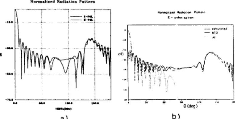
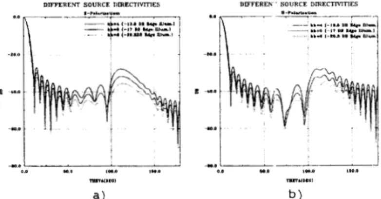
N U M E R I C A L RESULTS : The radiation patterns of the circu- lar reflector are obtained for various cases using t h e dual series based Riemann-Hilbert Technique. Figure 2(a) shows the comparison of E and H polarization cases. Since the edge effects are stronger for H- polarization, the side lobe levels are also higher. The circular reflector result is used t o approximate the radiation pattern of a parabolic re- flector. Figure 2(b) represents the comparision of t h e circular reflector solution with the parabolic reflector result of Jull and Suedan[2]. In addition, t h e effect of increasing source directivity for both polariza- tions is examined in Figure 3. Source directivity is increased with increasing kb and the results show that the side lobe levels are de- creased and the main beamwidth is increased. Figure 4 shows the radiation patterns of E and H polarization cases for different aper- ture dimensions. The edge illumination is -13.5dB below the aperture center for a reflector with f/D=0.5 and the aperture dimensions are taken as 10X,20X and 30X. It is seen the beamwidt h is narrower for a large aperture and sidelobe levels are more depressed.IV.
CONCLUSIONS : The CS approach is used with Dual-Series formulation for reflector antennas in two dimensions. By the present numerically exact solution, some principal results of reflector anten- nas are checked for a circular reflector. The results a r e compared with the results in [2] for a parabolic reflector. Some other parameters of reflector antennas like gain and radiation resistance can also be ob- tained by the method. Further, the method provides an opportunity to analyze t h e performance of reflector antennas over a ground plane or inside a radome.R E F E R E N C E S
[l]
L.B.
Felsen ” Complex source point solutions of the field equa- tions and their relation t o the propagation and scattering of Gaussian beams,” Symp. Math., ~01.18, pp 39-56, 1975[2] G.A.Suedan,
E.V.
Jull ”Beam diffraction by planar and parabolic reflectors,” IEEE trans. A P vol 39, no:& april 1991.[3] A.I. Nosich ”Green’s Function-Dual Series Approach in wave scat- tering by combined resonant scatterers,” in M.Hashimoto, M.Idemen and O.A. Tretyakov (eds.), Analytical and Numerxal Methods in EM
Wave Theory, Tokyo. Science House, 1992. [4] J0hn.D. Kraus, Antennas, McGraw-Hill, 1988.
Figure I : a ) Circular reflector antenna system error (i.e.A(Del))
b) Electrical length of
Figure 2: a) Comparision of E and H polarizations for circular reflector ka=120.57, kro=60.28, k b z 9 . 0 6 and 6=15 deg(D=lOX). b) Prediction of t h e radiation pattern of parabolic reflector. (f/D=0.96 and D=lOX)
Figure 3: Different source directivities ka=62.8, kro=31.4 and 6=30
deg(D=lOX). a ) E-polarization case b) H-polarization case
DIFTERENT APEFTURE DIMENSIONS
I--
-1
... -.i. ... . .... .
.
. ..DIFFERKNT APERTURE DIMENSIONS
.*-
...
... -1 i... . . ... . . i ,.
00.. U"* I.0.. m.0.I
b )
Figure 4: Different aperture dimensions. edge illumination).
6=30 deg, kb=4(-13.5 DB a) E-polarization case b) H-polarization case