Comparison of the Effects of Permeable, Impermeable and Monolithic Vertical-Face Submerged
Breakwaters on Tsunami Run-up Height
Emel IRTEM Ezgi SEYFİOGLU M.Sedat KABDASLI Balıkesir University Kilis 7 Aralık University Istanbul Technical University Balikesir/TURKEY Kilis/TURKEY İstanbul /TURKEY
ABSTRACT
Tsunamis are one of the most devastating coastal disasters, generated by mass water movements resulting from ground movements that can be triggered by earthquakes, submarine landslides and collapses. Various measures have been developed to reduce tsunami damage. One of the tsunami protections is submerged breakwaters. In this study we have analyzed the results of physical models to investigate the effects of different submerged breakwaters on tsunami run-up. In the experiments permeable, impermeable and monolithic vertical-face submerged breakwaters are used for different submergence depth and it is found that they reduce run-up heights by 21% - 43%, 19%- 37% and 28%- 59% respectively with respect to the case without submerged breakwater. It is also shown that the effect of submerged breakwaters on tsunami run-up depends upon the breakwater geometry.
KEY WORDS: tsunami; tsunami run-up height; permeable submerged breakwater; impermeable submerged breakwater; monolithic vertical-face submerged breakwater.
INTRODUCTION
The tsunamis that have occurred from the past to present have caused the loss of both lives and possessions. For this reason, measures were developed to reduce tsunami damage. These are structural precautions (breakwaters, groins,…), non-structural precautions (public awareness, evacuation procedures, tsunami warning systems etc.), natural barriers (coastal forests etc.) (Irtem et al., 2009; Irtem et.al., 2011).
In this study, the effect of the different submerged breakwaters on tsunami run-up height has been investigated experimentally. Submerged breakwaters are barriers whose crest rise is below the still water level. The waves from offshore are compelled to break and their energy decreases, with part of it being transferred to the ground (Kabdaşlı et al., 1996).
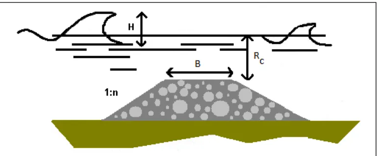
The effect of a submerged breakwater can be described in terms of the ratios B/L and Rc/H. Here, B is crest width, L the wavelength, Rc is the
submergence depth and H is the wave height. Decreasing these ratios will increase the transmission and thus decrease the effectiveness of the structure. The ratio B/L is almost zero, which corresponds to a high transmission (Van Der Plas, 2007).
Figure 1. Submerged breakwater
A lot of experimental and theoretical researches have been carried out, related to wave transmission of submerged structures. In the study presented by Kobayashi and Wurjanto (1989) wave transmission, reflection and breaking from impermeable submerged breakwaters was investigated. By Hedge (1995) in experiments conducted with different core porosity values it was found that the damage on sloped breakwater reduces as core porosity increases. d’Angremond et al. (1996) produced an equation for wave transmission coefficients that can be applied to rubble mounds and solid structures. Seabrook and Hall (1998) improved design equation for transmission in case of submerged breakwaters. The interaction between solitary wave and submerged rectangle structures was analyzed by Huang and Dong (2001) and by Huang et al. (2003). The breaker height of irregular waves passing beyond a submerged breakwater was surveyed experimentally. A comparison with regular ones was carried out and an empirical formula that measures the break limit of irregular waves according to experimental data was offered. The computation of wave transmission coefficients at detached breakwaters for shoreline response modeling was researched by Wamsley and Ahrens (2003). A numerical study which presents the transmission characteristics of submerged breakwaters was conducted (Rambabu and Mani, 2005). The influence of crest width, of the situation of first wave, of material properties and
of submersion depth on the transmission characteristics of submerged breakwaters was studied by using a matching method. Van der Meer et al. (2005) gave a summary of the DELOS research on wave transformation at low-crested structures. The pass and reflection of long waves from a trapeze breakwater was handled by Chang and Liou (2007). A semi-empirical model where the predictive equations have been obtained starting from a crude schematization of the physical processes that govern wave transmission was presented by Buccino and Calabrese (2007). A novel method to compute two dimensional waves on the behind of a submerged breakwater was offered (Calabrese et al., 2008).
In this study, the effect of three types of submerged breakwaters (permeable, impermeable and monolithic vertical-face) on tsunami run up height was investigated..
METHODS AND MATERIALS Experiments
Experiments were carried out in the wave channel of the Istanbul Technical University Hydraulic Laboratory. The wave channel has a length of 22.5 m, width of 1.0 m and height of 0.5 m. The side walls of the wave channel, as shown in Figure 1, are made of glass in order to improve visibility.
Figure 2. General view of the wave channel
A tsunami generation system was built with a plate whose motion is governed by a pressured air device. The plate has the dimensions of 0.97 m x 2.0 m x 0.002 m. The tsunami generation mechanism consists of a piston, a PHS16B bearing and a horizontal plate. The piston is a pneumatic cylinder, driven by a manually controlled system. As the piston moves vertically, the plate lifts off and displaces the adjacent fluid, thereby generating long waves (Gedik et al., 2004). The beach was formed by natural beach sand. The specific gravity of the sand used was 2.63 and the mean diameter of sand grains was 0.35 mm. The slope of the beach was 1:5, as shown in Fig. 1. In the position of 7 m in the wave channel, the submerged breakwater was placed as is portrayed in Fig.3, where Ru is the wave run-up height, d is the water depth, H is the wave height, Rc is the submergence depth and B is the crest width.
Figure 3. Experimental set-up
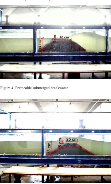
Permeable face was prepared by laying fine material with grain diameters of 5-8 cm on coarse core material with grain diameters of 10-13 cm approximately. The core of impermeable submerged breakwater was prepared by applying a material with diameters of 5-8 cm on gravel dust material that was firmly compressed (Figure 4). The consequence is that the impermeable submerged breakwater has a slope made of gravel dust as the core and stones as cover (Figure 5). The monolithic vertical-face submerged breakwater was built as a box and within the box a lead weight was put to supply enough static stability against the forces exerted by the waves (Figure 6).
Figure 4. Permeable submerged breakwater
Figure 6. Monolithic vertical-face submerged breakwater
Experiments were carried out for the cases that are listed in Table 1.
Table 1. The cases treated in the lab experiments
RESULTS
The change of run-up height with incident wave height in the cases of permeable submerged breakwater, impermeable submerged breakwater, monolithic vertical-face submerged breakwater as well as for cases without breakwaters are given in Tables 2-4 and in Figures 7-14 where dimensionless quantities (Ru/d and H/d) are plotted.
Table 2. Run-up height values corresponding to incident wave height values for the permeable submerged breakwater
case-I case-II case-II' case III
Incid en t W a v e H eig h t (c m ) 1.27 0.73 0.89 0.71 3.30 3.04 3.11 2.86 5.45 5.51 5.19 5.45 7.09 7.11 6.66 7.39 8.42 8.27 8.21 7.71 5.48 5.50 5.50 5.44 8.49 8.52 8.45 8.41 11.06 10.85 10.63 11.17 12.68 13.20 12.23 12.56 14.18 13.89 13.61 13.36 Ru n -u p H ei g h t (c m ) 2.16 2.94 3.33 2.94 6.28 10.00 10.20 10.00 11.37 13.92 14.51 15.89 14.12 18.04 16.67 19.22 16.47 19.22 18.43 18.83 10.59 13.53 13.53 14.51 14.71 17.65 16.87 18.83 17.45 20.59 19.61 21.38 18.63 21.97 20.40 22.16 19.81 22.75 21.38 22.95
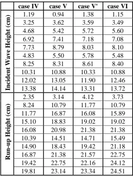
Table 3. Run-up height values corresponding to incident wave height values for the impermeable submerged breakwater
case IV case V case V' case VI
Incid en t Wa v e H eig h t (c m ) 1.19 0.94 1.38 1.15 3.25 3.62 3.59 3.49 4.68 5.42 5.72 5.60 6.92 7.41 7.18 7.08 7.73 8.79 8.03 8.10 4.83 5.50 5.78 5.48 8.25 8.31 8.61 8.40 10.31 10.88 10.33 10.88 12.02 13.05 11.90 12.46 13.38 14.14 13.31 13.72 Ru n -u p H ei g h t (c m ) 2.35 3.14 4.12 3.73 8.24 10.79 11.77 10.79 11.77 16.87 16.08 15.89 15.10 18.83 19.02 19.02 16.08 20.98 21.38 21.38 10.39 14.51 14.71 15.49 14.90 18.43 19.42 21.18 16.87 21.38 21.57 22.75 19.42 22.75 22.16 24.12 19.81 23.14 23.34 24.51 Permeable Impermeable Monolithic
Cases B Rc B Rc B Rc Cases I 25 0 - - 25 0 M-I II 25 5 - - 40 0 M-I' II' 40 5 - - 25 5 M-II III 40 10 - - 40 5 M-II' IV - - 25 0 25 10 M-III V - - 25 5 40 10 M-III' V' - - 40 5 VI - - 40 10
Table 4. Run-up height values corresponding to incident wave height values for the monolithic vertical-face submerged breakwater
M-I M-I' M-II M-II' M-III M-III'
Incid en t Wa v e H eig h t (c m ) 1.71 1.71 1.62 1.42 1.14 1.35 2.94 2.96 3.67 3.22 3.67 3.15 5.62 4.65 6.07 5.61 6.45 5.53 7.24 6.11 7.92 7.08 8.10 6.79 8.40 7.36 9.19 8.39 9.37 8.06 5.53 4.80 6.68 5.86 5.90 8.44 7.95 7.79 9.03 9.80 8.44 11.47 10.06 12.10 11.44 12.75 11.03 13.39 11.80 14.01 12.94 14.35 12.64 14.93 12.07 15.47 14.28 15.45 13.03 R un -u p H ei g h t (c m ) 1.18 1.57 4.32 3.73 4.51 4.71 4.51 5.30 10.20 9.42 11.97 11.38 8.63 8.44 14.51 14.51 17.06 16.67 10.79 9.61 16.67 16.67 19.02 18.83 12.75 11.57 17.85 17.65 20.20 19.42 7.45 7.45 13.73 12.55 16.28 11.18 10.98 17.06 15.89 20.40 20.79 13.73 13.14 19.02 18.43 22.75 21.97 15.69 14.71 20.00 19.81 23.53 22.95 17.06 16.28 20.40 19.61 23.53 23.34 0 0,2 0,4 0,6 0,8 1 1,2 0,0 0,2 0,4 0,6 H / d R u / d case M-II'
without submerged breakwater case V'
Figure 7. Run-up height vs. wave height (case M-II', case V' and without submerged breakwater)
0 0,2 0,4 0,6 0,8 1 1,2 0,0 0,2 0,4 0,6 H / d R u / d case M-II'
without submerged breakwater case II'
Figure 8. Run-up height vs. wave height (case M-II', case II' and without submerged breakwater)
0 0,2 0,4 0,6 0,8 1 1,2 0,0 0,2 0,4 0,6 H / d R u / d case M-III'
without submerged breakwater case VI
Figure 9. Run-up height vs. wave height (case M-III', case VI and without submerged breakwater)
0 0,2 0,4 0,6 0,8 1 1,2 0,0 0,2 0,4 0,6 H / d R u / d case M-III'
without submerged breakwater case III
Figure 10. Run-up height vs. wave height (case M-III', case III and without submerged breakwater)
0 0,2 0,4 0,6 0,8 1 1,2 0,0 0,2 0,4 0,6 H / d R u / d case M-I
without submerged breakwater case IV
Figure 11. Run-up height vs. wave height (case M-I, case IV and without submerged breakwater)
0 0,2 0,4 0,6 0,8 1 1,2 0,0 0,2 0,4 0,6 H / d R u / d case M-I
without submerged breakwater case I
Figure 12. Run-up height vs. wave height (case M-I, case I and without submerged breakwater)
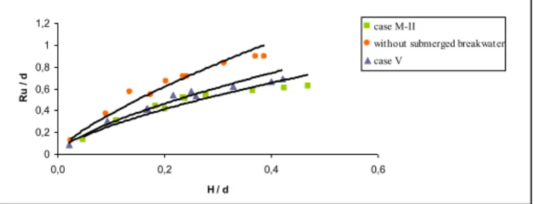
0 0,2 0,4 0,6 0,8 1 1,2 0,0 0,2 0,4 0,6 H / d R u / d case M-II
without submerged breakwater case V
Figure 13. Run-up height vs. wave height (case M-II, case V and without submerged breakwater)
0 0,2 0,4 0,6 0,8 1 1,2 0,0 0,2 0,4 0,6 H / d R u / d case M-II
without submerged breakwater case II
Figure 14. Run-up height vs. wave height (case M-II, case II and without submerged breakwater)
Data of the experiments were evaluated for permeable, impermeable and monolithic vertical-face submerged breakwaters and the comparison of the reduction of tsunami run-up height is given Table 5.
Table 5. Comparison of the reduction of tsunami run-up height
Permeable Submerged Breakwater Impermeable Submerged Breakwater Monolithic Vertical-Face Submerged Breakwater B= 40 cm 21% 19% 28% Rc= 10 cm B = 25 cm 25% 23% 33% Rc = 5 cm B = 40 cm 26% 21% 33% Rc = 5 cm B = 25 cm 43% 37% 59% Rc = 0 cm CONCLUSIONS
The tsunami run-up height can be decreased by means of natural barriers like coastal forests or by means of hard coastal structures. In this study the effects of permeable, impermeable and monolithic vertical-face submerged breakwaters on the tsunami run-up height were investigated and compared.
As a result of this study, it was seen that permeable submerged breakwaters are more effective than impermeable submerged
breakwaters and monolithic submerged breakwaters are more effective than both permeable and impermeable submerged breakwaters.
With respect to the case with no structures at all, when B= 25 cm, Rc=0 cm, a permeable submerged breakwater reduces the tsunami
run-up height by 43%, impermeable submerged breakwater by 37% and monolithic vertical-face submerged breakwater by 59%. It seems that the effect of crest width to run-up height is less than the effect of the submergence. Consequently, it can be said that monolithic submerged breakwaters are the most effective in reducing tsunami run-up height. Monolithic submerged breakwaters with a vertical front face force a tsunami to increase its height in order to reach the necessary head for overtopping and after overtopping tsunami waves happen to be irregular behind the breakwater because of energy dissipation during the splash.
Monolithic vertical-face submerged breakwaters can be even more effective if they are used jointly with other prevention measures such as coastal walls and coastal forests.
ACKNOWLEDGEMENTS
This research was supported by the Research Foundation of Balikesir University, under Project No. 2010/02. The authors would like to thank Dr. Nuray Gedik from Balikesir University and Mr. Hasan Yalcin from the technician staff of the Istanbul Technical University Hydraulic Laboratory.
REFERENCES
Buccino, M, and Calabrese, M (2007). “Conceptual approach for prediction of wave transmission al low-crested breakwaters,” Journal of Waterway, Port, Coastal, and Ocean Engineering, Vol 133, pp 213-224.
Calabrese, M, Vicinanza, D, Buccino, M (2008). “2D Wave setup behind submerged breakwaters,” Journal of Ocean Engineering, Vol 35, pp 1015-1028.
Chang, KH, Liou, CJ (2007). “Long wave reflection from submerged trapezoidal breakwaters,” Journal of Ocean Engineering, Vol 34, pp 185-191.
d’Angremond, K, van der Meer, J, De Jong, R (1996). “Wave transmission at low-crested structures,” Proc., 25th Coast. Engrg. Conf.,ASCE, pp 2,418-2,427.
Gedik, N, İrtem, E, Kabdaşlı, S (2004). “Laboratory Investigation on Tsunami Runup,” Ocean Engineering, Vol 32, pp 513-528. Huang, JC, Chang, HH, Hwung, HH (2003). “2D Structural
permeability effects on the interaction of a solitary wave and a submerged breakwater,” Journal of Coastal Engineering, Vol 49, pp 1-24.
Huang, JC, Dong, C-M (2001). “On the interaction of a solitary wave and a submerged dike,” Ocean Engineering, Vol 43, pp 265-286. Irtem, E, Gedik, N, Kabdaşlı, S, Yasa, NE (2009). “Coastal forest
effects on tsunami run-up heights,” Ocean Engineering, Vol 36, pp 313-320.
Irtem, E, Seyfioglu, E, Kabdaşlı, MS (2011). “Experimental Investigation on the effects of Submerged Breakwaters on Tsunami Run-up Height," Journal of Coastal Research, Vol SI 64, pp 516-520.
Kabdaşlı, S, Mutlu, T, Ünal, E. (1996). “Comparison of the Performance of Submerged Breakwaters and Classic Breakwaters,” 1st National Coastal Engineering Symposium, Samsun, November 1996.
submerged breakwaters,” Journal of Waterway, Port, Coastal , and Ocean Engineering, Vol 115, pp 662-680.
Rambabu, AC, Mani, JS (2005). “Numerical prediction of performance of submerged breakwaters,” Journal of Ocean Engineering, Vol 32, pp 1235-1246.
Seabrook, S, Hall, K (1998). “Wave transmission at submerged rubble mound breakwaters,” Proc. 2 th Coast. Engrg. Conf., ASCE, pp 2,000-2,013.
Van der Meer, JW, Briganti, R, Zanuttigh, B, Wang, B (2005). “Wave transmission and reflection at low-crested structures: Design
formulae, oblique wave attack and spectral change,” Coastal Eng., Vol 52, pp 915–929.
Van Der Plas, T (2007). “A Study into the Feasibility of Tsunami Protection Structures for Banda Aceh & A Preliminary Desing of an Offshore Rubble-Mound Tsunami Barrier,” Final Thesis Report, Amersfoort, Delft University of Technology, pp 1-24.
Wamsley, TV, Ahrens, P (2003). “Computation of wave transmission coefficients at detached breakwaters for shoreline response modeling,” Proc. Coastal Structures, JA Melby, Ed., ASCE, Reston, Va., pp 593–605.