.оітім а· -Ä11 ' Ді-ТІйІ«Д;ТІ'ѴЕ LA
lS'EL
íMO "F
^ 4мц)г«мгі> ai·'·'к ‘
|Ím«m|¿ ii y '‘4UÍi^
i|i
'vwM 'ti. ¡i w ' ■ ^ t Í ' t Z b r - 3i ^ ¿0*·ί
wΏ 5 Λ ■
i/’’"·» -WMif'. ■
y %
,! *í,.
¡4 · · :^. í , IH. «1 7 *4 V«i ¡
y Д·"! «·.··,'· w : Г ѵ íí · -J W S 4 4 -.¡J? ' i' i*·'i J Ύ ‘ -i' ‘sfEXPLOITING AN ALTERNATIVE LABELING FOR
EFFICIENT HYPERCUBE ALGORITHMS
A THESIS
SUBMITTED TO THE DEPARTMENT OF COMPUTER ENGINEERING AND INFORMATION SCIENCE
AND THE INSTITUTE OF ENGINEERING AND SCIENCES OF BILKENT UNIVERSITY
IN PARTIAL FULFILLMENT OF THE REQUIREMENTS FOR THE DEGREE OF
MASTER OF SCIENCE
By
Cavit Aydin
July 1991
c cK\j, V ? ■-n V· .'' ■ ·11
I certify that I have read this thesis and that in my opinion it is fully adequate, in scope and in quality, as a thesis for the degree of Master of Science.
Assoc. Prof. D ir Cevdet Aykanat(Principal Advisor)
I certify that I have reiid this thesis and that in my opinion it is fully adequate, in scope and in equality, as a thesis for the degree of Master of Science.
Mehmet Baraj^
I certify that 1 have read this thesis and that in my opinion it is fully adequate, in scope and in qualit}'^, as a thesis for the degree of Afaster of Science.
Asst. Prof. (Dr. H. Altay Güvenir
Approved for the Institute of Engineering and Sciences:
Prof. Dr. Mehmet(0afay
ABSTRACT
EXPLOITING AN ALTERNATIVE LABELING FOR
EFFICIENT HYPERCUBE ALGORITHî\IS
Cavit Aydın
M.S. in Computer Engineering And Information Science
Supervisor: Assoc. Prof. Dr. Cevdet Aykanat
July 1991
In this work, a new labeling scheme for hypercube multicomputers is proposed. The proposed labeling is exploited by developing algorithms on the SIMD hy percube model with the indirect I/O port register enhancement. Through the construction of some algorithms and reduction in their SIMD complexities, it is shown that this new labeling is superior to the common labeling used so far. In the common labeling, processor index' computations required for nearest neighbor communications in ring and mesh embeddings can be performed in
0(d) time in a (¿-dimensional hypercube. These routing computations can be performed in
0
(1
) time only if a number of gray code conversion tables are used. In the proposed labeling, these routing computations can be performed in0
(1
) time, using simple decimal arithmetic and without the need of any code conversion tables, which provides a flexible parallel programming envi ronment. Instead of gray code ordering in the common labeling the natural decimal ordering of the processors in the proposed labeling suffices for the em bedded ring and mesh operations. In most of the SIMD algorithms developed, best previous MIMD complexities are reached. Finally, the generalization of the proposed labeling for the generalized hypercube architecture is presented which provides algorithmic compatibility in embedded ring operations.ÖZET
v e r i m l i
HİPERKUP ALGORİTM ALARI İÇİN
ALTERNATİF BİR İNDEKSLEMENİN KULLANIMI
Cavit Aydın
Bilgisayar ve Enformatik Mühendisliği Bölümü Yüksek Lisans
Tez Yöneticisi: Assoc. Prof. Dr. Cevdet Aykanat
Temmuz 1991
Bu çalışmada hiperküp çokişlemcileri için yeni bir indeksleme yöntemi ö- nerildi. Önerilen indeksleme, dolaylı giriş-çıkış kaydedicisi eklenmiş SIMD hiperküp modeli üzerinde algoritmalar geliştirilerek kullanıldı. Bazı algorit maların geliştirilmesi ve SIMD çalışma zamanlarının düşürülmesiyle, bu j-eni indekslemenin alışılmış indekslemeden daha üstün olduğu gösterildi. Alışılmış indekslemede, içe konmuş halka ve ağlardaki en yakın komşu haberleşmesinde gereken işlemci indeksi hesaplamaları d-boyutlu hiperküpte O (d) zamanında yapılabilmektedir. Bu rota hesaplamaları eğer gray kodu çeviri tabloları kul lanılırsa 0 (1 ) zamanda yapılabilir. Bu rota hesaplamaları, önerilen indeks lemede esnek bir paralel programlama ortamı sağlayacak şekilde sabit zamanda, basit ondalık aritmetik kullanarak ve hiçbir kod çeviri tablosuna ihtiyaç ol madan yapılabilmektedir, içe konmuş halka ve ağ işlemlerinde, alışılmış in- dekslemedeki gray kodu sıralaması yerine önerilen indekslemedeki doğal on dalık sıralama yeterli olmaktadır. Geliştirilen çoğu SIMD algoritmalarında önceki en iyi MIMD zamanlarına ulaşılmış bulunulmaktadır . Son olarak, içe konmuş halka işlemlerinde algoritmik uyumluluk sağlayan, önerilen indeksle menin genelleştirilmiş hiperküp çok işlemcileri için genelleştirilmesi sunulmak tadır.
ACKNOWLEDGMENT
I am grateful to my supervisor Assoc. Prof. Dr. Cevdet Aykanat for his invaluable encouragement and guidance throughout the development of this thesis.
It is my pleasant duty to express my gratitude to all of my friends for their moral support and motivation, particularly in times of despair and flurry.
Contents
1 Introduction 1
2 Proposed Labeling and Embeddings 7
2.1
Recursive R e d e fin itio n ...' 7
2.2
Basic P roperties...8
2
.2.1
Finding the neighbors of a processor8
2
.2.2
Label C o n v e rsio n ...11
2.2.3 Minimal Routing D is ta n c e ... 13
2.2.4 R o u t i n g ...
14
2.2.5 Decomposition into sub-hypercubes... 17
2.3 E m b ed d in g s... 18
2.3.1 Ring Embedding 18 2.3.2 Mesh E m b e d d in g ...
21
3 SIMD Hypercube Model 26 4 Fundamental Algorithms 29 4.1 Data B r o a d c a s t... 29
4.2 Window B r o a d c a s t ... 29
4.3 Data C ir c u la t io n ... 30
4.4 Window Circulation
3
I 4.5 Data S u m ...3
]^ 4.6 Power2
S h ift... 32 4.7 S h i f t ...33
4.8 Prefix Sum35
4.9 Consecutive S u m ...3,5
4.10 Data A ccum ulation...
36
4.11 Adjacent S u m ...
37
4.12 R a n k in g ...
37
7
5 One Dimensional Convolution 40
5.1 0 { M ) m e m o r y ...
41
5.2
0
(1
) m em ory ...47
6 Generalization 51
6.1
Alternative Structure For Generalized H y p e r c u b e ... 516
.1.1
A Mixed Radix Number S y ste m ... 516
.1.2
Description Of The New GHC structure 527 Conclusions 55
List of Figures
1.1
The block diagram of an SIMD architecture...2
1.2
The block diagram of an MIMD architecture..3
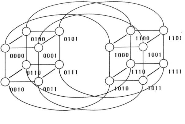
1.3 A 4-dimensional hypercube. 5
2.1 Recursive construction with the common labeling for d=4. 9
■t
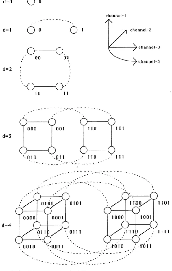
2.2 Recursive construction with the proposed labeling for d=4. . . . 10
2.3 Neighbors of 13 in the proposed labeling...
12
2.4 The masks used for finding the neighbors of a node... 15
2.5 e-routing with the proposed labeling (from 0001 to 1100) . . . . 16
2.6 Decimal order ring embedding for a 4-hypercube with the
i^ro-posed labeling. 19
2.7 Decimal order connections of the nodes in a 4-hypercube with
the proposed labeling. 19
2.8 Mesh embedding for 4-hypercube in the proposed labeling. . . .
22
2.9 A 4 X 4 mesh with end-around connections. 23
2.10 A 4 X 2 mesh embedded by using the proposed labeling. 23
2.11 A 4 x 2 x 2 mesh embedded by using the proposed labeling. . . 25
4.1 The sub-rings in a 4-dimensional hypercube... 31
Chapter 1
Introduction
Parallel architectures can be classified according to their memory organization, number of instruction streams supported and processor organization.
■I
According to the memory organization, parallel architectures have two cla.s- sifications: multiprocessors and multicomputers. In a multiprocessor, proces sors share a common memory or a common memory address space. Sjmchro- nization and coordination among processors are achieved through shared vari ables. On the other hand, a multicomputer has neither a shared memorj' nor a shared memory address space. Synchronization and coordination among pro cessors and data exchange between the local memories of the processors are achieved by explicit message passing via the interconnection network. In this work, discussions are restricted to multicomputers.
According to the number of instruction streams supported, there are two categories relevant to the multicomputers discussed in this work: SIMD (Single Instruction Multiple Data stream) and MIMD (Multiple Instruction Multiple Data stream). Figure
1.1
illustrates the block diagram for an SIMD multicom puter. In an SIMD architecture, only the control processor has the capability of instruction fetching, sequencing and decoding. The processing elements (PEs) in an SIMD architecture execute the instructions broadcasted by the control unit in a synchronous manner. Hence, PEs in an SIMD multicomputer exe cute the same instruction at given cycle for the data in their local memories. Figure1.2
illustrates the block diagram for an MIMD multicomputer. In an MIMD multicomputer, each PE has the capability of instruction fetching, se quencing and decoding from its local memory. Hence, MIMD architectures are usually asynchronous and different PEs may execute different instructions at any time.CHAPTER 1. INTRODUCTION
I/O
CHAPTER 1. INTRODUCTION
I/O
CHAPTER 1. INTRODUCTION
Classification according to the processor organization is in fact classification according to the interconnection network used to connect the processors of the multicomputer. There are several interconnection schemes for multicomputers. These include ring, mesh, tree and hypercube. Among the parallel topologies proposed so far, hypercube topology has received considerable attention. The popularity of the hypercube topology is due to the following:
• Many other widely used topologies such as rings, meshes, and trees can be successfully embedded onto an hypecube [
2
]. Hence, it can simulate the algorithms written for these topologies. This property makes the hy percube topology a powerful candidate to be an interconnection topology for general purpose parallel architectures.• In a d-dimensional hypercube N = 2^ processors can be connected by us ing only d connections per processor while having a maximum distance of
d between any two processors This property gives a significant advantage over other topologies such as ring, mesh and tree. Figure 1.3 illustrates a 4-dimensional hypercube with binary encodings of the processors.
• Hypercube topology is completely symmetric and can be decomposed into sub-hypercubes (section, 2.2.5), allowing to implement recursive divide- and-conquer algorithms [
10
].• Several multicomputers have been commercially built by using the hyper cube interconnection toj^ology (e.g. by Intel, NCUBE, Ametek, Floating Point Systems, and Thinking Machine).
In this work, the discussions are restricted to hypercube-connected SIMD and MIMD type multicomputers.
Hypercube topology can be recursively constructed as described in Chap ter
2
. The nodes are labeled according to this recursive definition. Since it has been first introduced, the same technique has been used to label the nodes of the hypercube. Routing and distance computations between any two nodes, finding the neighbors of a given node and all other computations required for interprocessor communications are performed by using this common labeling. These computations strongly affect the performance of the parallel algorithms developed for the hypercube.In this work, a new hypercube labeling is proposed and an SIMD hypercube model is suggested which successfully exploits the proposed labeling (Chap ters
2
& 3). The new labeling is achieved by changing the interconnectionCHAPTER 1. INTRODUCTION
1 101
n i l
CHAPTER 1. INTRODUCTION
rule between the nodes during the recursive construction as is discussed in Section
2
.1
. Chapter2
presents the important consequences of the proposed change in the hypercube labeling after Section2
.1
. The new algorithms for finding the neighbors of a given node, routing between two nodes, finding min imal routing distance and decomposition into sub-hypercubes are presented in Section2
.2
. In common labeling all the operations are done by bitwise cal culations. These operations can also be done by bitwise calculations in the proposed labeling as is given in Chapter 2. In order to sliow the regularity and power of the proposed labeling their corresponding decimal calculations are also presented with their corresponding formulas. The important embeddings to the hypercube topology such as the embeddings of ring and mesh topologies are also presented in Section 2.3. While providing the methods for embed ding, their corresponding algorithmic properties and formulas are also given. The developments in the SIMD machines and the SIMD model used in this work are presented in Chapter 3. The SIMD model selected here exploits the proposed labeling for the development of efficient hypercube algorithms. In Chapter 4, it is shown that the algorithmic complexities of some fundamental■ /
algorithms such as Power2Shift, Data Accumulation and AdjacentSum can be reduced asymptotically by using the proposed labeling. For some other algo rithms, such as DataCirculation, WindowCirculation, Shift etc., the constant factors in the time complexities are reduced. Using these fundamental algo rithms efficient algorithms for the one dimensional convolution operation are developed in Chapter 5. It is also shown that MIMD complexities are reached by exploiting the proposed labeling on the selected SIMD model. Chapter
6
shows how the new labeling can be generalized for the Generalized Hypercube Architecture which can provide algorithmic compatibility for some applica tions.
Chapter 2
Proposed Labeling and Embeddings
This chapter presents the derivation and the properties of the proposed label ing. These properties are crucial for the efhcient implementation of parallel algorithms. The diiferences between the common labeling and the proposed labeling are also discussed. Finally, some important embeddings using the proposed labeling are presented.
2.1
Recursive Redefinition
A d-hypercube can be constructed recursively from lower dimensional hyper cubes [
2
]. Consider two identical (d-f)-hypercubes whose nodes are labeled likewise by (d-f)-bit binary numbers. A d-hypercube is obtained by connect ing each node . . . ÍiÍq of the first (d-i)-hypercube to the node .. . iiioof the second having the same label. The nodes of the resultant d-hypercube is labeled by representing the nodes of the first (d-f)-hypercube by
0
i'd_2
... iiioand those of the second by lid-2 .. .ÍiÍq. Figure
2.1
illustrates the steps for the common recursive construction of a 4-hypercube beginning from a0
-hypercube. In this common labeling, there is an edge between any two nodes if and only if the binary representation of their labels differ by one and only one bit.The new labeling is achieved by only changing the interconnection rule be tween the nodes of the two identical (d-i)-hypercubes during the recursive con struction of a d-hypercube. Each node .. .iiio of the first (d-i)-hypercube is connected to the node .. .í[Íq of the second whose binary representation is a bitwise complement of id-i ■.. iiio· Here, denotes the complement of bit
ik. Figure 2.2 illustrates the steps for the proposed recursive construction of a
CHAPTER 2. PROPOSED LABELING AND EMBEDDINGS
an edge between any two nodes if and only if the binary representation of their labels differ only by k consecutive least significant bits for
0
< < d —1
.2.2
Basic Properties
2.2.1
Finding the neighbors of a processor
Two nodes (processors) are defined to be neighbors if they are directly con nected with an edge (communication link). In the common labeling, two pro cessors are neighbors if and only if their binary labels differ by only one bit. In a d-dimensional ЬзфегсиЬе (d-hypercube), each processor has d communi cation channels
(0
< 1' < d —1
) and d neighbors. The neighbors of a processor Zd_i. . . i\io at channel к for 0 < к < d — 1 are the processors г^_х.. .. fi?'o for 0 < к < d — 1. Here, denotes the complement of bit Ú-. For example, in a4
-dimensional hypercube (See Figure 2.1), the neighbors of processor 0 (0000) at channels к = 0 ,1 ,2 ,3 are the processors 1 (0001), 2 (0010), 4 (0100) and8
(1000
) respectively. In the global sense, channel-A: represents disjoint communication links between pairs of processor whose binary labels differ only in the ¿-th bit position.In the proposed labeling, two processors are said to be neighbors if and only if their binary labels differ only in the least significant к consecutive bits (i.e. ik-\ ■ · .fifo)· The neighbors of a processor id-\ ■ ■ -ú fo at channel к for
0
< ^ < d — 1 are the processors id-\ . . . 0 < ¿ < d —1
. In the proposed labeling, channel-A; represent 2'^~^ disjoint communication links between 2'^~^ disjoint pairs of processors whose binary labels differ exactly in the least significant /г-consecutive bits. For example, in a 4-dimensional hypercube (See Figure 2.2), the neighbors of processor 0 (0000) at channelsк = 0 ,1 ,2 ,3 are the processors
1
(0001), 3 (0011), 7 (0111) and 15 (1111) respectively.In the proposed labeling, neighbors of a given node can easily be calculated by using decimal arithmetic. For a given node X , its d neighbors on d channels in a d-hypercube can be calculated by using the formula
Yi = (2‘+ ^ - l ) - ( X m o d 2 ’+^) + 2‘+^(;i: d i v
2
‘ +i)= (2*+^ - 1) + 2'+2(X div 2‘+i) - X (2.1)
for
0
< f < d —1
. Here, div represent the integer division operation. A power of two div operation can simply be achieved by a shift operation. Example 2.1CHAPTER 2. PROPOSED LABELING AND EMBEDDINGS d=0
O »
channel-1 d=l6 »
6
o— o,
00 O'l d=2 ■ ■ O10
O · '
1 1 d=3 d = 4 1101 n i lCHAPTER 2. PROPOSED LABELING AND EMBEDDINGS 10 d=0
O o
channel-1 d=l6
«
6
,-o— o·..
00 01 d=2 d=3■■■O—
O ··
11 10 ♦o— o
000 0016 —
6
. 011
' p i o
100
101
1 10 ' / o i n / T011 0
0 0 0 0
0001
d = 4o
a
0 ^ —
0
a
o
01
H S X \0101
n i l d c o / ^1110
o
lOo;0
;1011
/ ·1010
0011
^'0.010
• . . n o o
¿ - n o i
. ^ **CHAPTER 2. PROPOSED LABELING AND EMBEDDINGS 11 i =
0
channel-0
Vq — (2
^ ~1
) + 2^(13 div2
^) — 13 = 1 - 1 - 2 4 - 1 3 = 12 z = 1 channel-1 Yi = (2^ —1
) 2^(13 div2
^) — 13 = 3 - H 2 4 - 1 3 = 14 i = 2 channel-2 = (2^ -1
) d- 2‘‘ (13 div 2^) - 13 = 7 + 1 6 - 1 3 = 10 i — 3 channel-3 Ys — (2“* — 1) + 2^(13 div 2'*) — 13 = 15 + 0 - 1 3= 2
·/Example 2.1: The neighbors of 13 on each channel (0 to 3).
shows the computations for finding the neighbors of node 13 in a 4-dimensional hypercube by using the equation
2
.1
. Figure 2.3 illustrates the neighbors of node 13 in a 4-dimensional hypercube.2.2.2
Label Conversion
When the ring embedding into the hypercube is considered (Section 2.3.1), the proposed labeling corresponds to the decimal ordering and the common labeling corresponds to the gray code ordering. Hence, conversion between the common labeling (Xc) and the proposed labeling (A^p) is achieved by using decimal-to-gray or gray-to-decimal conversion. The conversion from Xp to Xc
is a two step operation. It is independent from the number of bits in the binary representation of the decimal number. Hence it is an 0 (1 ) operation. If Xp is the binary label of a processor then the corresponding Xc is
X , = Xp © X
where X® denotes the binary number obtained by shifting Xp right one bit. Conversion from the common labeling to the proposed labeling is a (d — l)-step operation where d is the dimension of the hypercube. Hence, its complexity is 0 (d ). If Xc is the binary label of a processor, then its corresponding label Xp in the proposed labeling is
CHAPTER 2. PROPOSED LABELING AND EMBEDDINGS 12
Neighb or connections
Other connections
Source node
Neighbor node
10CHAPTER 2. PROPOSED LABELING AND EMBEDDINGS 13
(0)
( 1 ) ( 2 ) ( 3 ) ( 4 ) ( 5 ) ( 6 ) ( 7 )000 001 010 on 100 101 no 111
( d e c i m a l o r d e r ) i i i i i i i i(0) (1)
( 3 ) ( 2 ) ( 6 ) ( 7 ) ( 5 ) ( 4 )000 001 on 010 no 111 101 no
(gray o r d e r )Example 2.2: Example for the conversion operation for a 3-climensional hyper cube.
A"e =
22
io = (10110)2
and Xp = 29io = (11101
),2
.22 to 29 29 to
22
10110
11101
01011
OHIO0
00111
11101
00011
00001
0
10110
Example 2.3: Conversion from 22 to 29 (from proposed labeling to common labeling) and from 29 to 22 (from common labeling to proposed labeling).
where X®'’ denotes the binary number obtained by shifting Xc right by j-bit.
Therefore, the conversion from the proposed labeling to the common label ing in a d-dimensional hypercube is an
0
(1
) operation but the reverse is an0(d) operation. That brings an advantage to the proposed labeling in devel oping SIMD hypercube algorithms.
Example 2.2 demonstrates the relation between the two labelings for a 3-dimensional hypercube and Example 2.3 demonstrates the conversion oper ation for a 5-dimensional hypercube.
2.2.3
Minimal Routing Distance
In the common labeling, the minimum routing distance between any two nodes with binary labels P,· and Pj is equal to the hamming distance between their binary labels, (H(Pi, Pj)). Hamming distance between two binary numbers is defined as the number of bits they differ. The hamming distance between two nodes X and Y can be obtained by using
CHAPTER 2. PROPOSED LABELING AND EMBEDDINGS 14
where, © denotes the bitwise exclusive-OR operation and C{.) denotes the function which returns the number of ones in the binary representation of its argument. The following theorem is given to find the minimum routing distance between two nodes in the proposed labeling.
T h e o r e m In the proposed labeling, the minimum routing distance be tween any two nodes with binary labels P,· and Pj is the hamming distance between Pi © Pj and (Pi © PjY, where (P,· © PjY denotes the binary number obtained by shifting Pi ® Pj right one bit.
P r o o f The minimum routing distance between any two nodes P,· and Pj
can be found by converting it to the common labeling.
Pi Pi ©
P-Pj P, © P /
■ /
Hence, the minimum routing distance R(Pi,Pj) between the nodes Pi and
Pj is
R(Pi,Pi) = H( ( P<SPn, ( Pi <l >P· ) ) = C((Pi © P /) © (i=,· © P /) )
Using the associativity property of the © operation
R{Pi,Pj) = C { { P i ® P j ) ® { P f ® P J ) ) (2.2)
However, P / ® P^ = (P,· © PjY since © is a bitwise operation. Hence Eq.
2.2
becomes
R{Pi,Pj) = C { { P i ® P j ) ® { P i ® P j Y ) = / / ( ( P © P , ) , ( P © P , ) ^ )
2.2.4
Routing
Since the labeling of the nodes are changed, the routing procedure must be different. Procedure 2.1 is the routing procedure which is similar to the e- routing [
11
] used for the common labeling.In the procedure e-route S is the source processor, D is the destination processor and d is the degree of the hypercube. As it is used in section 2.2.3,
CHAPTER 2. PROPOSED LABELING AND EMBEDDINGS 15 procedure e-route (S, D, d);
/2
= © i?) © (S '0
Z ))^ for i = to d — 1 do if ( R i =1
) then S' = S © (2
*’+ i - l ) ; send data to S] endif endfor end] { e-route )Procedure 2.1: The routing procedure.
2
^ -1
=0 . . .0001
2
^ -1
=0 ... 0011
2
^ -1
=0 ...0111
2
“^ -1
= ^...nil
d —bits
Figure 2.4: The masks used for finding the neighbors of a node.
A^ denotes the number obtained by shifting A right one bit. R{ denotes the bit of its binary representation for 0 < i < d —
1
. The number of ones in the binary representation of the variable R is the hamming distance betweenS and Zl, (H(S, D)). As it is used in the e-routing procedure for the common labeling, the algorithm starts from the lower dimension and continues to the higher. If =
1
then the source address is masked with the the number (2'·*·^ — 1) to find the next node to be visited. The number (2*+^ —1
) is used because in the proposed labeling two processors are connected if and only if their least significant k bits are complement of each other for I < k < d(Section
2
.2
.1
). Therefore the masks used in Figure 2.4 complements the least significant k bits for1
< A: < d when the © operation is used. In Figure 2.5, the routing from the source address0001
to the destination address1100
for a 4-hypercube is demonstrated. As it is easily seen from the Procedure2.1
the routing is completed in at most d steps for a d-hypercube.CHAPTER 2. PROPOSED LABELING AND EMBEDDINGS 16
Used links
Source & Destination nodes
Unused links
In te rm ed ia te nodes
01 0 1 1 0 1
c
0 0 0 0]
0 0 0 1 1 1 1 1c s
J
1 1 1 0/ / S
01 30/'f o i o i
A
1 0 1 0 0 1 1t ^ o i o
L ^ H o o
^ ^ 0 1100 1
1010CHAPTER 2. PROPOSED LABELING AND EMBEDDINGS 17
2.2.5
Decomposition into sub-hypercubes
In some applications such as recursive divide-and-conquer algorithms, decom position into sub-hypercube is needed. This decomposition can be done by partitioning the d-hypercube into two (d-l)-hypercube along the channel for
0
< A: < d -1
. In the common labeling a d-hypercube can be partitioned into two (d-l)-hypercube along an arbitrary channel in the following way.• first group includes the processors having the label
id-l ■ ■ ■ . . . ¿
1^0
• second group includes the processors having the label
¿d-i · · · U-+ilU
—1
. . . ¿ifo ,,That is, the N’'· bit of the labels of the first group is 0 and it is 1 for the second group. Hence, a d-hypercube can be partitioned into two (d-l)-hypercube in d ways. In the proposed labeling a d-hypercube can be partitioned into (d- l)-hypercubes by using decimal arithmetic. A d-hypercube can be partitioned into two (d-l)-hypercubes along the channel in the following way.
• first group includes a processor X , if
( ( X -f 2^) mod N) div 2^'·*·^ is even
• second group includes a processor X , if
( ( X +
2
^') mod N) div 2'=+^ is o d d(2.3)
(2.4)
In this way, a d-dimensional can be partitioned into (d-l)-dimensional sub hypercubes in d ways in the proposed labeling. Each one of these two (d- l)-hypercubes can in turn be decomposed into two (d-
2
)-dimensional sub hypercubes similarly replacing N by N/2 in the equations 2.3 and 2.4. This recursive decomposition scheme can be carried d times until0
-dimensional sub hypercube (individual processors) are obtained.The decomposition in the proposed labeling is slightly more cumbersome compared to the common labeling although both have 0 (1 ) complexity. For tunately, in general, recursive decomposition is performed beginning from the most significant bit (k = (d -l)-th channel) and proceeding towards the least
CHAPTER 2. PROPOSED LABELING AND EMBEDDINGS 18
significant bit. In this case, the decomposition scheme in the proposed labeling reduces to the one in the common labeling. Assume that, a d-hypercube is to be decomposed into 2‘^~^ disjoint A:-dimensional sub-hypercubes using this scheme. In this scheme, processor indices in each k-subhypercube differ only in their least significant A;-bits in both labelings. Each ¿-dimensional sub-hypercube in this decomposition scheme is in fact called window. For example, a 5-hj''percube can be decomposed into 2®“ ^ = 4 3-dimensional windows denoted by
00
¿2
¿i¿o,01
í2
*i?'o, H^Í2Í\ioi in both labelings.2.3
Embeddings
In this section, ring and mesh embeddings in the proposed labeling are dis cussed. The algorithmic properties discussed for these embeddings are exr ploited in the development of the algorithms given in the following chapters.
2.3.1
Ring Embedding
In the common labeling, ring embedding is obtained by binary reflected graxj code ordering of the labels of the processors in one dimension. However, in the common labeling finding the nearest neighbor of a processor in the embedded ring topology requires
0
(d) complexity since gray-to-decimal and decimal-to- gray conversions are needed. These routing computations in the ring embedded hypercubes can be performed in0
(1
) time only if a gray-to-decimal code con version table is used. Due to recursive definition of the hypercube topology, sub-ring embedding exist in windows which may be referred to as window ring embeddings. Some fundamental algorithms require similar concurrent oper ations in the subrings embedded in disjoint windows. In a d-hypercube such operations requires maintaining d-different gray-to-decimal code conversion ta bles in each processor for a flexible parallel programming environment. The proposed labeling avoids the use of such tables as is discussed in the following paragraph.In the proposed labeling, ring embedding is very trivial. Sorting the pro cessors in ascending order according to the decimal values of their binary labels forms a ring. Figure 2.6 and Figure 2.7 illustrates the ring embedding on a 4-dimensional hypercube with the proposed labeling. This property of the new labeling will be exploited to develop efficient fundamental algorithms for SIMD hypercubes.
CHAPTER 2. PROPOSED LABELING AND EMBEDDINGS 19
Used
links
Unused links
Figure 2.6; Decimal order ring embedding for a
4
-hyi3
ercube with the proposed labeling.Figure 2.7: Decimal order connections of the nodes in a 4-hypercube with the proposed labeling.
CHAPTER 2. PROPOSED LABELING AND EMBEDDINGS 20
There are two types of communication in a ring: forward and backward. Let Ps be the source processor and Pj, be the destination processor. Then the destination processor (next processor) P^ for forward communication can be identified as
Pd = P s + l (2.5)
Similarly, the destination processor (previous processor) P^ for backward com munication can be identified as
p ; = p. 1 (2,6)
In the proposed model, the algorithms that uses the ring embedding often have the statements
q = (p + l ) m o d A ' ’;
q = (p — 1) mod N·,
(2.7)
(
2
.
8
)
Once the q value is calculated it always shows either the next or previous processor in the ring embedding. Therefore, there is no need to change it throughout the execution of the algorithm. The next processor of the last processor (Pn-i) is the first processor (Po)· Similarly, the previous processor of the first processor Pq is the last processor Pn-i- So modulo N arithmetic
should be used. Here, N — 2'^ denotes the size of the hypercube.
Note that, decimal ordering in each ^-dimensional windows of size W =
2
^' forms a ring. Example 2.4 illustrates the different size window ring embed dings with decimal ordering in the proposed labeling for a 4-hypercube. The decimal computations given in Equations 2.7 and2.8
for performing nearest neighbor communication in ^-dimensional window ring embedding should be modified asq = (p + 1) mod W + W{p div IT);
q = (p - 1) mod W + W(p div W)]
(2,9)
(2.1 0)
where W = 2'^ denotes the size of the windows. For example, the next processor of processor p = 5 and p =
7
for (^ =2
)-dimensional window ring embeddings (IT = 4) in a 4-dimensional hypercube can be computed as follows:q = (5 -b 1) mod 4 + 4(5 div4)
= 6
q = (7 + 1) mod 4 + 4(7 div4) = 4
CHAPTER 2. PROPOSED LABELING AND EMBEDDINGS 21 k = 3 (H/ =
8
) { 0 - 1 - 2 - 3 - 4 - 5 -6
- 7 } ;{8
- 9 - 10 - 11 - 12 - 13 - 14 - 15} k = 2 { W = 4) ( 0 - 1 - 2 - 3 } ; {4 - 5 -6
- 7}; { 8 - 9 - 1 0 - 1 1 } ; { 1 2 - 1 3 - 1 4 - 1 5 } k = l ( W^ = l ) { 0 - 1 } ; { 2 - 3 } ; { 4 - 5 } ; { 6 - 7 } ; { 8 - 9 } ; { 1 0 - 1 1 } ; { 1 2 - 1 3 } ; { 1 4 - 1 5 }Example 2.4: Decimal order A;-dimensional window ring embeddings in a
4
- dimensional hypercube for1
< ^ < 3.which can be verified from Example 2.4. As is .seen in the equations 2.9 &
2
.10
, the computations required by each individual processor to determine their nearest neighbor processor in any window ring embedding can be performed• in constant time
7 • using simple decimal arithmetic
• without using any table (i.e. gray-to-decimal conversion table)
Note that, equations 2.9 & 2.10 are valid for any processor in any window. That is, there is no need to determine in which window the processor resides. Hence, this equation can effectively be used in SIMD hypercube models without necessitating instruction maisking.
2.3.2
Mesh Embedding
In the common labeling,
2
-dimensional mesh embedding is obtained by 2-gray code ordering of the labels of the processors in two dimensions. However, in the common labeling finding the nearest neighbor processor of a processor in the embedded mesh topology requires 0(d) complexity since gray-to-decimal and decimal-to-gray conversions are needed as in the case of ring embedding discussed in section 2.3.1. This complexity can be reduced to 0 (1 ) time only if a gray-to-decimal code conversion table is used. Due to variable size of meshes to be embedded into the hypercube, the number of tables can increase which may be infeasible to handle. The proposed labeling avoids the use of such tables as is discussed in the following paragraphs.In the proposed labeling, a, N — m x n mesh can be embedded by sorting the processors in ascending order according to their decimal labels, and ordering them in snake-like row major order. The snake-like row major ordering is also
CHAPTER 2. PROPOSED LABELING AND EMBEDDINGS 22 0 7
8
14 0 13 0 0 0 0 0 0 0 1 0 0 1 0 001 1 01 11 01 10 0101 0 1 0 0 1 0 0 0 1001 1 0 1 0 101 1 1111 1 1 1 0 1101 1100Figure 2.8: Mesh embedding for 4-hypercube in the proposed labeling. 7 used in [3] for parallel sorting on a mesh-connected processor array. Figure 2.8 illustrates the embedding of a 4 x 4 mesh on a 4-dimensional hypercube with tlie proposed labeling. In this figure, processors are also shown with their binary labels to illustrate that the proposed embedding satisfies mesh interconnection topology. As is seen in Figure 2.8, the given embedding also satisfies end- around mesh interconnections. This is explicitly drawn in Figure 2.9 for a
4
-hypercube. In Figure 2.10 a 4 x2
mesh is illustrated. When m and n are power of two numbers then the end-around connections also hold as is seen in Figure 2.10.There are four types of communication in a mesh: east, west, north and
south. Let Ps be the source processor and Pj, be the destination processor. In the east communication odd rows increment their processor number and even rows decrement their processor number. Let us define a variable disp which can take only -f-1 and
—1
values. Also define another variable base. For aN = m
2
X mi mesh the equations for disp and base depending on the Ps will bedisp = 1 — 2 * ((Ps div 7Tii) mod 2) (
2
-11
)base = mx(Ps div rni) (
2
.12
)So the east communication is achieved by
P^ = (Ps + disp) mod mi + base (2.13)
In west communication even rows decrement their processor number and odd rows increment their processor number. Because of this —disp should be used.
CHAPTER 2. PROPOSED LABELING AND EMBEDDINGS 23
Figure 2.9: A 4 X 4 mesh with end-around connections.
0 1 3 2 4 5 7 6 000 001 011 010 100 101 111 110
CHAPTER 2. PROPOSED LABELING AND EMBEDDINGS 24
Then the formula is
P¿ = {Ps — (lisp) mod mi + base (2.14)
The north and south types of communications can not be done by just in crementing or decrementing the processor labels. Therefore different formulas must be used. The soxdh communication is achieved by
P¿ = {2mi(Ps div nii -b 1) - P, - 1) mod N
and north communication is achieved by
P'¿ = (2?77.i(Ps div m i) - Ps - 1) mod N
(2.15)
(2.16)
Notice that rn^ is never used in the formulas. In the case of ?t7i = 1 a ring is
obtained. As is seen in equations 2.11 to 2.16, the computations required bj'^ each individual processor can be performed in constant time by using decimal , arithmetic and without using any tables (i.e. gray code conversion table).
For n dimensional mesh embeddings, (i.e. ?77„ x ··· x m.2 x 7/ii), the method used for 2-dimensional mesh embedding can be generalized. Actu ally an 7772 X mesh is m
.2
times replication of size ?77i ring (See Figure 2.10). The ordering of the processors are reversed for even rows. That is, at iP'· rows the ordering of the i^rocessors are reversed for 1 < 7 < m2
and i is even. From that observation an m„ x · · · x m2
x ?77i mesh can be labeled in a more generalized way.Let
1 ^
1 ^
*2
< m2
1 < 7„ < m„
An TUk X · · · X m2 X mi mesh is formed by using niktimes the m k - \ x · · · x m2 x 7?7i meshes such that the ordering of the processors of ruk-i x · · · x m2 x ?t7i meshes are reversed for even i^s for all 1 < ^ <
77
. Figure 2.11 illustrates a 4 x 2 x 2 mesh embedding.CHAPTER 2. PROPOSED LABELING AND EMBEDDINGS 25
I n E
Chapter 3
SIM D Hypercube Model
The discussions in this thesis are restricted to hypercube multicomputers. Both SIMD and MIMD type hypercube multicomputers are considered. In an SIMD / model, each processor executes the same instruction broadcasted by the con trol processor in a synchronous manner. The MIMD multicomputers usually operate in asynchronous manner and may execute different instruction at any given time. Recently, SIMD models proposed and implemented are enhanced by certain hardware features. These enhancements are provided to increase the flexibility and power of the SIMD multicomputers. The first enhancement is the introduction of the ’’ instruction masking” to enable only a subset of the processing elements (PEs) during the synchronous execution.of a global instruction. The second enhancement is providing an indirect address register within each PE. Each PE can perform the same operation on the data available in different locations in its local memory indexed through the use of its local indirect address registers. These local indirect address registers can be set to different values through an SIMD instruction sequence by use of instruction masking and/or individual PE indexes.
In the SIMD model used by Sahni [4], each PE can communicate to its neighbor PE on the same channel at any given time. The broadcasted instruc tion indicates the channel over which the communication should be performed. For example, in a 2D mesh multicomputer, P E ’s can communicate only to their east ( or west or south or north) neighbors at any given time. The third enhancement to avoid the restriction in the SIMD multicomputers is providing each PE with a local indirect I/O port register. P E ’s can communicate to their neighbors on different channels through the use of local indirect I/O port register. These local indirect address registers can be set to different channel values through an SIMD instruction sequence by use of instruction masking
CHAPTER 3. SIMO HYPERCUBE MODEL 27
and/or individual PE indexes. For example, in a 2D mesh multicomputer some of the PEs may communicate to their west neighbor while some others communicating to their east neighbors during the execution of the same global communication instruction. In this model, the instruction broadcasted by the control processor only indicates that communication operation is to be carried during that instruction cycle. Each PE determines the channel over which it should communicate through the use of the current value in its local indirect I/O port register. In this work, this indirect I/O port register enhancement is included into the SIMD model to exploit the hypercube labeling proposed in Chapter 2.
The properties of the SIMD hypercube model using the proposed labeling, the programming features and the assumptions used are:
• There are N — processing elements {PEs) interconnected using hyper
cube interconnection topology. A PE with binary label is
directly connected to the PEs with binary labels id-\ ■■.
for 0 < A: < d — 1, (Chapter 2). Here, i'f. denotes the complement of bit U-. Each P E is indexed with an equivalent decimal label in the range [0,
N-1].
• The PEs are only capable of performing some basic arithmetic operations. Each PE has a local memory to hold data only. That is, there are no executable instruction in the local memories.
• Parentheses ( ’ ()’) are used to index PEs and brackets ( ’ []’) to index local arrays. Thus, A[i] refers to the element of array A, and A(i) refers to the A register of PE{. Also, A [/](t) refers to the element of the local array A in PE,.
• All PEs are controlled by a separate control processor which holds the actual program in its program memory. Control processor is responsible for instruction sequencing, fetching, and decoding. Furthermore, control processor is responsible for broadcasting decoded instructions together with instruction masks to PEs for execution. An instruction mask is a boolean function. Control processor can enable certain PEs for execution and disable some others through the instruction mask. For example,
A{p) := A{p) + 1, (p < 2')
is a global miraprocessor statement where (p < 2') is a mask that enables only those PE s whose P E index is less than 2‘ .
CHAPTER 3. SIMD HYPERCUBE MODEL 28
Each P E has a special p register which holds its own index according to the proposed labeling. Sometimes, the PE indexing of local registers will be omitted for the sake of clarity. Hence, the above intraprocessor
statement is equivalent to the following statement.
H : = A + 1, { p < T )
• Each P E has a special q register which holds the index of the destination
PE for interprocessor assignment statements. Interprocessor assignment statements have the following form
A{q) <— A(p), {instruction mask)
In the above statement, each P E satisfying the instruction mask, concur rently transmits its local A register data to the destination PE indicated in its local q register. The transmitted data is then written to the local
A registers of the destination PEs. Interprocessor communications are allowed only between directly connected PEs.
• The number of unit routes are considered in complexity analysis. A unit route is the transmission of the data between two directly connected PEs.
The communication links are assumed to be unidirectional. Hence, any data exchange between two directly connected P E s takes two unit routes.
Chapter 4
Fundamental Algorithms
Some of the fundamental operations discussed in this section perform window operations. A window of size W in a d-hypercube is defined as a /j-dirnensional subcube (k < d) with W = 2^ PEs. The PE indices in each window differ only in their least significant k bits. Hence, the d-hypercube is assumed to be partitioned into disjoint N^/W (¿= lo g
2
lT)-dimensional windows. Most of the SIMD fundamental algorithms presented in this chapter are efficient than the best previous SIMD algorithms [4] and they have the same complexity with the best previous MIMD fundamental algorithms [5].4.1
Data Broadcast
In this algorithm, the data in the A register of P Eq is broadcast to all other
PE s. The flow of data follows the recursive construction steps of the hypercube given in Section 2.1. The instruction mask (p < is used to prevent unnecessary message transmissions in the network. The number of unit routes is exactly logj N, which means a complexit)'· of 0(log2 A^). The best previous SIMD and MIMD algorithms for this operation has the same complexity ([4], [5]). The corresponding procedure is Procedure 4.1.
4.2
Window Broadcast
WindowBroadcast is a more general version of the Broadcast. In that case broadcast is made in windows with dimension k ( k < d). The originators in each windows can be arbitrary. In the Procedure 4.2 the originating processor
CHAPTER 4. FUNDAMENTAL ALGORITHMS 30 procedurebroadcast ( A, d ); fori:= l tod do ? p © (2‘ - 1) A (?) ^ A{p), (p < 2·-^); endfoT] end] { broadcast } Procedure 4.1: Broadcast. 'procedureWindowBroadcast ( A, k ); for i: = l to k do q ;= p ffi(2 ‘· - l)i
A(q) ^ A ( p ) , (P i., = p;_,y,
endfor,
end; { WindowBroadcast }
Procedure 4.2: Window Broadcast.
is P'. The complexity of this algorithm is 0{k) same as the best previous SIMD and MIMD algorithms [4], [5].
4.3
Data Circulation
In this algorithm, the data in the local A register of each P E should be circu lated so that this data visits each of the N PEs exactly once. The algorithm for data circulation is trivial in the proposed labeling. It exploits the ringem bedding described in Section 2.3.1. Since the ascending ordering of PEs forms a ring, the successor of each P E in the ring can easily be identified by sim ply incrementing its index by one without using any exchange-sequence tables used in [4] (see Figures 2.6 & 4.1). Data circulation takes a total of N shifts and therefore the algorithm has a time complexity of 0 { N ). Best previous SIMD algorithm uses exchange sequence tables to handle this operation with the same time complexity [4]. The corresponding procedure is Procedure 4.3.
procedure Circulate (A ); q '.= {p + 1) mod N\ for i:= l to N do A{q) 4- A(p); endfor, end·, { Circulate } Procedure 4.3: Circulation.
CHAPTER 4. FUNDAMENTAL ALGORITHMS 31
Figure 4.1: The sub-rings in a 4-dirnensional h3q5ercube.
procedure WindowCirculate (A,W ); 9 ·= (p + 1) nic)d W + W{p div W): for i:= l to W do
M<i) ^ ^ (p );
endfor,
end] { WindowCirculate }
Procedure 4.4: Window Circulation.
4.4
Window Circulation
WindowCirculate operation is a more general version of Circulate operation. It performs the circulation in windows of size W {W < N). Figure 4.1 illustrates the sub-rings exist in the sub-windows of a 4 dimensional hypercube. The difference can be seen in Procedure 4.4. Its complexity is 0 (W ). Here, p div W
denotes [p /W j. No previous SIMD and MIMD algorithms are given for this operation in the literature.
4.5
Data Sum
DataSum operation sums the data in A registers of F E s in each window of dimension k. The final sums are accumulated in the A registers of the PEs
having the least index in each window. It actually performs the following operation
k—1
fo r all windows (4.1)
CHAPTER 4. FUNDAMENTAL ALGORITHMS 32
procedure DataSum (A,k);
for i: = l to k do
^ : = p © ( 2 ‘ - l ) ;
B{q) <— A(p), (2^“ ‘ < p mod 2^ < 2*^“ ’+^);
A(p) := A{p) + B{p)^ (0 < P mod 2^' < 2*^“ ^);
endfor,
end·, { DataSum }
Procedure 4.5: Data sum.
Procedure 4.5 demonstrates how this operation can be performed. Its com plexity is 0 (k ) which same as the best previous SIMD and MIMD algorithms for this operation ([4], [5]).
4.6
Power2 Shift
The Power2Shift operation shifts the data in the local A register of each PE
circularly counterclockwise or clockwise by i PE s in the ring where i is a power of 2. Power2Shift is a very useful procedure. It is used by some other funda mental operations, such as Shift a,nd PrefixSum. Hence, its performance is a crucial factor in the performance of those operations. The Power2Shift algo rithm presented here can be performed in 0 (1 ) complexity by using the ring
embedding proposed in refring-emb. One shift is performed in 1 step and all other power of 2 shifts can be performed in 2 steps. A 2" shift is performed by calling two 2"“ ^ mirror shifts, for n > 0. For n=0, which is a 1 shift, simply a mirror 1 shift is made. Note that, mirror 1 shift does not change the order of data. MirrorShift takes only one step, therefore, Poiuer2Shift requires at most 2 steps. Example 4.1 shows the initial data contents of the local A
register of each PE in a 3-dimensional hypercube. A 4 shift is performed by two successive mirror 2 shifts. The mirror shift becomes clear if the PE inter connections in Figure 2.7 are examined. The reason for the name MirrorShift
is that it reverses the order of the data after the shift operation. Note that, two successive mirror shifts corrects the order of data. This algorithm takes
0{ Ioq2{N/i)) time in [4] where i is the shift size. Hence, the algorithm pro posed here outperforms the algorithm given in [4] by performing the operation in constant time (2 steps). The previous MIMD algorithm for this operation also have 0 (1 ) complexity (see [6]) but has at most 4 steps which has 2 more steps than the SIMD algorithm presented.
CHAPTER 4. FUNDAMENTAL ALGORITHMS 33
procedure MirrorShift (A,k,W,dir);
i := p div 2^·,
q := ((i + dir)2^'^^ — p — 1) mod W + W[p divW )
^(<?) ^ ^(p);
end] { MirrorShift }
Procedure 4.6; Mirror Shift.
procedure Power2Shift (A,k,W,dir); f/’ k=0 then
MirrorShift (A, 0, W, dir)
else
MirrorShift (A, k—1, W, dir); MirrorShift (A, k—1, W, dir);
endif]
end] { Power2Shift }
Procedure 4.7; Power of 2 shift.
I MirrorShift procedure given in Procedure 4.6 shifts the A register data of 2^ P E s, to the next 2^ P E s in windows of size IP in the direction indicated by
dir. In the algorithm given below, dir = 1 indicates a counterclockioise shift, whereas dir = 0 indicates a clockwise shift operation. PowerSShift procedure given in Procedure 4.7 shifts the A register data of all P E s by 2^' positions in windows of size W in the direction indicated bv dir.
4.7
Shift
Shift algorithm is used to shift the A register data circularly counterclockwise
by arbitrary shift size. Since any integer number can be represented as the sum of powers of 2, this algorithm is implemented by calling successive power of two shifts. In a hypercube of size A'^, any shift size i can be represented as the summation of at most log
2
N power of 2 numbers. Since each of these power of two shifts can be done in at most 2 steps, the total execution takes at most 2 log2
N steps. However, shift direction can be re^■ersed by performing clockwiseshifts when more than d/2 bits are one in the d-bit binary representation of
i. Algorithm Shift checks this condition, and performs counterclockwise or
clockwise shift accordingly. Therefore, it takes at most log
2
N steps for any shift size i. The SIMD shift algorithm proposed in [4] takes 21og2 A ” steps. Hence, the proposed SIMD shift algorithm reduces the complexity by a constant factor of two. The corresponding procedure is Procedure 4.8.CHAPTER 4. FUNDAMENTAL ALGORITHMS 34 a b
b
g
e f c bg
d a h f c bg
f InitialRfter first mirror-2 After second mirror-2
Example 4.1: Example for 4-shift performed by Power2shift procedure for Af = 8 case.
procedure Shift (A, k, i);
dir := 1; i/ones(i) > k/2 then i := 2^ — i; dir := 0; endif] while i^O do j := l.log2iJ; Power2Shift ( A, j, 2^', dir); i i mod 2·^; end] endif] { Shift } Procedure 4.8: Shift.
CHAPTER 4. FUNDAMENTAL ALGORITHMS 35
procedure PrefixSum (A, k, S); 5(p) := A(p);
for i := 0 to k — 1 do A{p) := S{p);
Powei'2Shift (A, i, 2^, 1), (p mod 2^ < 2^ — 2');
S{p) := S{p) + A{p), {p mod 2^ > 2’ - 1);
endfor,
end; { PrefixSum}
Procedure 4.9: Prefix sum.
4.8
Prefix Sum
In this operation, A:-th P E in window i accumulates
k
S{iW = A {i W + i ) , 0 < i < NjW, Q < k < 14^ (4.2)
0=0
in its own S register [4]. This algorithm is implemented by using Power2Shift
algorithm given in section 4.6. In a hypercube of size N, logj successive power of 2 shift operations are performed, beginning from 1 up to N¡2 (i.e. 1 ,2 ,4 ,... N/2). Since a power of two shift takes at most 2 steps, the algorithm terminates in 2 log
2
N steps. The SIMD prefix sum algorithm proposed in [6] requires 3 log2
N steps. Hence, the complexity is reduced by a constant factor of 3/2. In addition, the algorithm proposed here is shorter and simpler than the one in [6]. The corresponding procedure is Procedure 4.9. Example 4.2 demonstrates tdie N = M = 8 case. The A registers hold the data and all are 1 to make the example understandable. The final values are in the S registers.4.9
Consecutive Sum
Consecutive sum operation is performed in windows of size M. Each processor has values X[0..M — 1] in its local memory. The consecutive sum operation is
M-l
A{j) = ^ X | ; ) ( 0 . 0 < j < M i=0
where i is the processor in a window. The processor in such a window is to compute the sum of the X[j] values in the M processors in its window.
The implementation of this operation is straightforward. Each processor makes a window circulation in windows of size M . During this circulation
CHAPTER 4. FUNDAMENTAL ALGORITHMS 36
B
sS B B B
A 1 1 1 1 1 1 1 1 S 1 1 1 1 1 1 1 1 A 1 1 1 1 1 1 1 1 S 1 2 2 2 2 2 2 2 A 1 2 1 2 2 2 2 2 S 1 2 3 4 4 4 4 4 A 1 2 1 2 1 2 3 4 S 1 2 3 4 5 6 7 8 initial After i=0 After i= l After i^2Example 4.2: Example for prefix sum operation for N = 8 case.
procedure ConsecutiveSum (X, M);
A\p mod M] := X[p mod M]\ for i = \ to M — \ do
Power2Shift(A, log
2
M , M , 0);A{p) := A{p) + X[{i + p) mod M ];
endfor,
Power2Shift(A, log
2
M, M , 0);end] { CosecutiveSum }
Procedure 4.10: Consecutive sum.
partial summation of A values are added by the corresponding X[j] values in each processor local memory. As it is easily seen, the complexity of this algorithm is 0 { M ) same as the best previous SIMD and MIMD algorithms ([4], [5]). It is shorter and simpler than the algorithm given in [4] as it is seen in Procedure 4.10.
4.10
Data Accumulation
Each P E has a local array A [0..M — 1] of size M , and has a data value in its local I register. After the completion of this operation each PE accumulates in its local A array the / values of the next M PEs (including itself) in the ring [4]
CHAPTER 4. FUNDAMENTAL ALGORITHMS 37
procedure DataAccum (A, I, M);
q ■= {p — 1) mod N-, Л[0] := I{p); for i: = l to M — 1 do Ali] ;= / ; endfor, end] { DataAccum}
Procedure 4.11: Data accumulation.
The operation i.s performed by M — I shifts of size 1. Since 1-shift takes 1 step in the proposed model, DataAccum can be completed in M — 1 steps which is same for the best previous MIMD algorithm [5]. The best previous SIMD algorithm for this operation requires 2{M — 1) + log^iN/M) steps [4]. Hence, the algorithmic complexity is reduced asymptotically when M <C N.
Otherwise, the algorithmic complexity is reduced by a constant factor which is greater than two. The corresponding procedure is Procedure 4.11.
4.11
Adjacent Sum
Each P E has a local array A[0..M — 1] of size M . Each P E j accumulates M-l
T{j) = + 0 mod M )), 0 < i < P
i= 0
in its local T register [7]. Each PE has also a local S register to hold inter mediate results. The algorithm performs M size 1 shifts for S and T which requires 2M steps. The final PowerSShift takes at most 2 steps. Therefore Procedure 4.12 can be completed in 2M-f2 steps. The best previous MIMD algorithm has a complexity of 2M + 4 [5]. SIMD algorithm for adjacent sum given in [4] takes 4M — 4 + 2\og2{NfM) steps. Hence, the algorithmic com plexity is reduced asymptotically when M <^ N. Otherwise, the algorithmic complexity is reduced by a constant factor which is greater than two.
4.12
Ranking
As it is defined in [6], the ranking operation for a given processor is the count of the number of selected processors in a window of size 2* which have processor


![[Nermidil Erner Binark'ın "Şakir Paşa Köşkü-Ahmet Bey ve Şakirleri" adlı kitabının tanıtım haberi]](data:image/gif;base64,R0lGODlhAQABAIAAAP///wAAACH5BAEAAAAALAAAAAABAAEAAAICRAEAOw==)