Experimental observation of true left-handed metamaterial
Koray Aydin, and Kaan GuvenDepartment of Physics, Bilkent University, Bilkent, 06800 Ankara, Turkey [email protected]
Ekmel Ozbay
Nanotechnology Research Center and Department of Physics, Bilkent University, Bilkent, 06800 Ankara, Turkey
Abstract: We report a true left-handed (LH) behavior in composite metamaterials. The magnetic
resonance of the SRR structure is demonstrated. Plasma frequency of the LH material is shown to be lower than that of the wires.
2000 Optical Society of America
OCIS codes: (120.7000) Transmission, (350.4010) Microwaves
1. Introduction
In 1968, Veselago predicted that a medium with negative permittivity, ε, and negative permeability, µ, will exhibit unusual physical properties like negative refraction, reversal of Doppler shift, backward Cherenkov radiation [1]. Recently, this idea is brought to experimental investigation in by constructing a composite metamaterial (CMM) consisting of two components which have ε (ω) < 0 and µ(ω) < 0 simultaneously over a certain frequency range, respectively [2,3]. While a medium with ε < 0 can easily be realized, e.g. by periodically arranged metallic wires [4], the µ(ω) < 0 was a challenge due to lack of magnetic charge. Pendry et al. suggested that a periodic array of metallic split ring resonator (SRR) structures exhibit µ(ω) < 0 close to magnetic resonance frequency ωp [5]. Various studies
employing different structure designs extended this investigation [2,3,6-8].
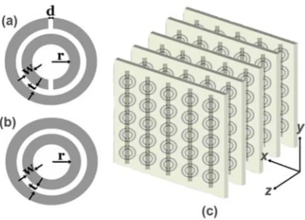
Fig. 1 Schematics of (a) a single split ring resonator (SRR) (b) a ring resonator with
splits closed (CSRR) (c) Periodic CMM composed of SRRs on one side, wires on the other side of dielectric board.
2. Magnetic resonance band gap of split ring resonators
In general, a SRR structure exhibits both magnetic resonance [5] induced by the splits at the rings, and electric resonance [9,10] by the dipole-like charge distribution along the incident electric field. A bandgap in the transmission spectrum of periodic SRR medium may be due to negative ε or negative µ or solely due to the periodicity. The ambiguity can be lifted by using a structure in which the splits in the ring resonators are closed (CSRR). A gap present in SRR but not in CSRR will then correspond to µ < 0. The SRR (Fig. 1(a)) and CSRR (Fig. 1.(b)) units are fabricated on circuit boards with a copper deposited layer of thickness 30 µm by etching. The geometrical parameters of the SRR are d = t = 0.2 mm, w = 0.9 mm and r = 1.6 mm as shown in Fig. 1(a).
h
T
JThC4
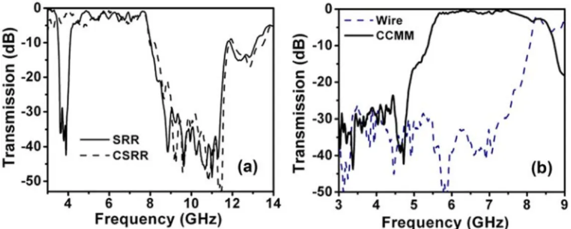
Fig. 2: Measured transmission spectra of (a) a periodic SRR medium (solid line) and periodic CSRR
medium (dashed line) between 3-14 GHz, (b) wires (dashed line) and closed CMM (solid line) composed by arranging closed SRRs and wires periodically.
Figure 2(a) shows the measured transmission spectra of periodic SRRs (solid line) and CSRRs (dashed line) between 3-14 GHz. The first bandgap (3.55-4.05 GHz) of the SRR medium is not present in the CSRR medium, indicating µ < 0. The second bandgap (8.1-11.9 GHz) is present for both the SRR medium and CSRR medium. This measurement clearly shows that the stop bands of an SRR medium can not be automatically assumed as “negative
µ” behaviour. Some of the observed gaps could also originate from the electrical response of the SRRs or from
Bragg gaps due to periodicity.
3. Downward plasma frequency shift
Another point to be discussed is the electric response of the CMM. Previously reported transmission results did not emphasize the interaction between SRR and wire structures. SRRs contribute to the effective permittivity of the CMM, causing a downward shift on the plasma frequency determined solely from wire structures [9]. To demonstrate this effect, a CMM consisting of periodic alternating layers of CSRRs and wires is used (Fig. 1(c)). Thickness, length and the width of the wires are 30 µm, 13.5 cm and 0.9 mm respectively. Figure 2(b) displays the measured transmission spectra of wire only medium and CMM consisting of CSRR and wire layers. The ωp of the
wire-only structure around 8 GHz, is reduced down to 5.3 GHz within the closed CMM structure. As seen in Fig. 2(b), ωp of the CMM is lower than that of the wire-only medium alone.
Fig. 3: Transmission spectra of SRRs (solid line), wires (dashed line) and CMM
(bold solid line)
C-528
JThC4
4. True Left-Handed Metamaterial
We have designed the present SRRs such that the first bandgap of SRR structure between 3.55 - 4.05 GHz is not obscured by this shift. The CMM structure is made of Nx = 5, Ny = 15, and Nz = 24 unit cells. Each unit cell has a
single SRR, and a copper wire from stacked SRR and wire layers, with lattice spacings ax = ay = 8.8 mm, az = 6.5
mm. The transmission spectra for SRR only (solid line), wire only (dashed line) and CMM (bold solid line) periodic structures are displayed in Fig. 4. The CMM structure allows propagation of EM waves between 3.6 and 4.1 GHz, where both ε and µ are negative. The CMM pass band exactly coincides with the stop band of SRR. The transmission peak at 3.9 GHz is -1.2 dB, which is a significantly high value for a material made of metals. We stress that, a similar transmission band is not present for a CMM composed of CSRRs and wires (Fig. 2(b)). The electric response contribution of SRRs is also evident here: If the ωp of the wire-only structure (dashed line in Fig. 4) were
used to identify the ε < 0 regime for the CMM, the transmission between 5.3 – 8 GHz would have occured in a regime with ε < 0 and µ > 0, which is not possible. However, as Fig. 2(b) suggests, the ε > 0 regime of the combined electric response of SRRs and wires starts at 5.3 GHz.
5. References
[1] V. G. Veselago, “The electrodynamics of substances with simultaneously negative values of permittivity and permeability,” Sov. Phys. USPEKHI, vol. 10, p. 509, 1968.
[2] D. R. Smith, Willie J. Padilla, D. C. Vier, S. C. Nemat-Nasser, and S. Schultz, “Composite medium with simultaneously negative permeability and permittivity,” Phys. Rev. Lett., vol. 84, p. 4184, 2000.
[3] R. A. Shelby, D. R. Smith, S. C. Nemat-Nasser, and S. Schultz, “Microwave transmission through a two-dimensional, isotropic, left-handed metamaterial,” Appl. Phys. Lett., vol. 78, p. 489, 2001.
[4] J. B. Pendry, A. J. Holden, D. J. Robbins, and W. J. Stewart, “Low frequency plasmons in thin-wire structures,” Journal of Physics: Condensed Matter, vol. 10, p. 4785, 1998.
[5] J. B. Pendry, A. J. Holden, D. J. Robbins, and W. J. Stewart, “Magnetism from conductors and enhanced nonlinear phenomena,” IEEE Trans. Microwave Theory Tech., vol. 47, p. 2075, 1999.
[6] Mehmet Bayindir, K. Aydin, E. Ozbay, P. Markos and C. M. Soukoulis, “Transmission properties of composite metamaterials in free space,” Appl. Phys. Lett., vol. 81, p. 120, 2002.
[7] Ekmel Ozbay, Koray Aydin, Ertugrul Cubukcu, Mehmet Bayindir, “Transmission and Reflection Properties of Composite Double Negative Metamaterials in Free Space,” IEEE Trans. Antennas Propag., vol. 51, p. 2592, 2003.
[8] T. Koschny, M. Kafesaki, E. N. Economou and C. M. Soukoulis, “Effective Medium Theory of Left-Handed Metamaterials,” Phys. Rev. Lett., vol. 93, p.107402, 2004.
[9] N. Katsarakis, T. Koschny, M. Kafesaki, E. N. Economou, and C. M. Soukoulis, “Electric coupling to the magnetic resonance of split ring resonators,” Appl. Phys. Lett., vol. 84, p. 2943, 2004.