MASTER THESIS
DEVELOPMENT OF SYNTHETIC NERVE ENDINGS FOR
AXO-AXONAL TRANSPORT AND TESTING AS ACETYLCHOLINE ION PUMP
Advisor: Assoc. Prof. Mehmet SANKIR Nazrin ABDULLAYEVA
Department of Micro and Nanotechnology
Anabilim Dalı : Herhangi Mühendislik, Bilim Programı : Herhangi Program
ii
Approval of Graduate School of Science and Technology
……….. Prof. Dr. Osman EROĞUL
Director
I certify that this thesis satisfies all the requirements as a thesis for the degree of Master of Science.
………. Prof. Dr. Murat ALANYALI
Head of Department
I certify that I have read the thesis named as “Development of Synthetic Nerve Endings for Axo-Axonal Transport and Testing as Acetylcholine Ion Pump” prepared by 151611001 numbered Master student of TOBB ETU, Institute of Natural and Applied Sciences, Nazrin ABDULLAYEVA on 10.04.2017 and that in my opinion it is fully adequate in scope and quality, as a dissertation for the degree of Master of Science.
Examining Committee members :
Assoc. Prof. Ayten TÜRKKANI (Chair) ... TOBB University of Economics and Technology
Advisor : Assoc. Prof. Mehmet SANKIR ... TOBB University of Economics and Technology
Assoc. Prof. Seha TİRKEŞ ... Atılım University
iii
STATEMENT OF DISSERTATION
Tez içindeki bütün bilgilerin etik davranış ve akademik kurallar çerçevesinde elde edilerek sunulduğunu, alıntı yapılan kaynaklara eksiksiz atıf yapıldığını, referansların tam olarak belirtildiğini ve ayrıca bu tezin TOBB ETÜ Fen Bilimleri Enstitüsü tez yazım kurallarına uygun olarak hazırlandığını bildiririm.
I declare that all the information in the thesis is presented in the frame of ethical behavior and academic rules, that the cited sources are cited completely, that the references are fully specified and that this thesis is prepared in accordance with TOBB ETU Institute of Natural and Applied Sciences thesis writing rules.
iv ABSTRACT
Master of Science
DEVELOPMENT OF SYNTHETIC NERVE ENDINGS FOR AXO-AXONAL TRANSPORT AND TESTING AS ACETYLCHOLINE ION PUMP
Nazrin ABDULLAYEVA
TOBB University of Economics and Technology Institute of Natural and Applied Sciences Micro and Nanotechnology Science Programme
Supervisor: Assoc. Prof. Mehmet SANKIR Date: APRIL 2017
Currently, more than 450 million people are globally suffering from some types of neurological diseases that can hardly be treated. These diseases are caused by distorted electrical and neurochemical signaling in the nervous system. The awareness of this worldwide problem is not brought in yet and definitive treatment has not been introduced so far. Most of therapies associated with neurological disorders are based on medical treatment such as medical therapy or electric stimulation. However, results are temporary and ineffective. The major effect obtained so far, was to conceal the disease and this was just not enough. In our study, by taking into consideration this problem we are presenting a biomimetic system that duplicates the function of a neural cell and helps to reinstitute the defective electrochemical transport of nervous system. Nerve impulses are communicated across synapses by diffusible molecules called neurotransmitters, of which one is acetylcholine. Acetylcholine molecules are contained in the axon foot inside vesicles. After the release of acetylcholine into the synaptic cleft, it binds to the cholinergic receptors located on the postsynaptic neuron and mediate
v
excitation or inhibition on postsynaptic cells and thus causing the transportation of neural signal. The system developed by our group resembles a two electrode structure with PEDOT:PSS deposited on them and a tiny 2 mm overoxidized region that cuts off electrical conductivity thus allowing only ionic transport. By using an easy and effective method of depositing conjugated polymers (PEDOT:PSS) on flexible substrates, a new design for organic bioelectronic devices has been developed. FTIR and Raman measurements have demonstrated that electrochemical overoxidation region which separates the PEDOT:PSS electrodes and allows ionic conduction has been achieved successfully. The influence of both electrical and ionic conductivities on organic electronic ion pump (OEIP) performances has been studied. The highest equilibrium current density, which corresponds to 4.81x10¹⁷ number of ions of acetylcholine was about 41 μA cm-2
observed for the OEIP with the electrical conductivities of 54 Scm-1. The OEIP performances were not changed much beyond this threshold electrical conductivity. Once Nafion™ has been applied for enhancing the ionic conductivity, the equilibrium current density increased about ten times and reached up to 408 μAcm-2. Therefore, it has been demonstrated that the OEIP performance mainly scales with the ionic conductivity. A straightforward method of producing organic bioelectronics is proposed here giving rise to their effortless mass production in the near future.
vi ÖZET Yüksek Lisans Tezi
AKSO-AKSONAL İLETIM IÇIN SENTETIK SINIR UÇLARI GELIŞTIRILMESI VE ASETILKOLIN İYON POMPASI OLARAK TEST EDILMESI
Nazrin ABDULLAYEVA
TOBB Ekonomi ve Teknoloji Üniversitesi Fen Bilimleri Enstitüsü
Mikro ve Nanoteknoloji Anabilim Dalı
Danışman: Doç. Dr. Mehmet SANKIR Tarih: NISAN 2017
Günümüzde 450 milyondan fazla insan, tedavi edilemeyen nörolojik hastalıklardan küresel olarak muzdarip. Bu hastalıklar, sinir sisteminde bozulmuş elektriksel ve nörokimyasal sinyallerden kaynaklanır. Dünya çapında bu sorunun farkındalığı henüz kazandırılamadı ve bugüne kadar kesin bir tedavi yöntemi bulunamadı. Nörolojik bozukluklarla ilişkili tedavilerin çoğu tıbbi terapi veya elektrik stimülasyonu gibi tedavi yöntemleridir. Bu tedavi yöntemlerinden elde edilen sonuçlar ise maalesef geçici süreliğine etkilidir. Çalışmamızda, bu problemi göz önüne alarak, bir sinir hücresinin işlevini çoğaltan ve sinir sisteminin kusurlu elektrokimyasal iletiminin tamir edilmesine yardımcı olan bir biyomimetik sistemi sunmaktayız. Sinir uyarıları, sinapslar boyunca sinir iletici olarak adlandırılan asetilkolin molekülleri tarafından iletilir. Asetilkolin molekülleri, veziküllerin akson ayağında bulunur. Asetilkolin'in sinaptik yarık içine salınmasından sonra, postsinaptik nöron üzerinde bulunan kolinerjik reseptörlere
vii
bağlanır ve postsinaptik hücreler üzerinde uyarılma veya inhibisyona aracılık eder ve bu şekilde sinir sinyalinin taşınmasına neden olur.
Grubumuz tarafından geliştirilen sistem, üzerinde PEDOT:PSS bulunan iki elektrot ve yalıtılmış, sadece iyonik taşınmaya izin veren 2 mm'lik aşırı okside bölgeye sahiptir . Esnek yüzeyler üzerinde konjuge polimerlerin (PEDOT:PSS) kaplanmasının kolay ve etkili bir yöntemi kullanılarak, organik biyoelektronik cihazlar için yeni bir tasarım geliştirilmiştir. FTIR ve Raman ölçümleri, PEDOT:PSS elektrotlarını ayıran ve iyonik iletime izin veren elektrokimyasal aşırı oksidasyon bölgesinin başarıyla elde edildiğini göstermiştir. Asetilkolin iyonlarının 4.81x10¹⁷
kadarına tekabül eden en yüksek akım yoğunluğunun 54 Scm-1
elektriksel iletkenliği olarak gözlemlenen yaklaşık 41 μAcm-2 idi. Organik elektronik iyon pompası performansları bu denge iletkenlik değerinin çok ötesinde değişmedi. Nafion ™, iyonik iletkenliği arttırmak için uygulandığında ise, denge akım yoğunluğu yaklaşık on kat artmış ve 408 μAcm-2'ye ulaşmıştır. Bu nedenle,
OEIP performansının esas olarak iyonik iletkenlik ile ölçeklendiği gösterilmiştir. Yakın gelecekte zahmetsizce seri üretim yapmalarını sağlamak için, organik biyoelektronik üretimi basit bir yöntem önerilmiştir.
Anahtar Kelimeler: Iyon pompası, Elektrisel iletken polimerler, PEDOT:PSS, Iyonomerler
viii
ACKNOWLEDGMENT
First of all, I would like to thank my advisor Assoc. Prof. Mehmet SANKIR for his support and effort he has spent on me. For all I have learnt from him and all the massive experience I gained under his supervision. It was a great pleasure to work with him along my master degree. Additionally, I would like to offer my special thanks to Assoc. Prof. Nurdan DEMIRCI SANKIR who also lead me and enlightened me throughout my master education. I wish to express my great appreciation to TOBB University of Economics and Techology for providing me scholarship during my master education. Thanks to my family who were always there to support and encourage me and made me feel precious no matter how far they were. Finally, thanks to my fiance who tolerated me at my most stressful and hectic moments and made me believe that everything is possible as long as we want.
ix CONTENTS Page ABSTRACT………...iv ÖZET………...vi ACKNOWLEDGMENT………viii CONTENTS………..ix LIST OF FIGURES……….xi LIST OF TABLES………...xiii ABBREVIATIONS……….xiv LIST OF SYMBOLS………...xv LIST OF EQUATIONS………..xvi 1. INTRODUCTION………...…..1 1.1 Aim of Study………...1 1.2 Motivation of Study………...1
1.3 Conductive Polymers and Ionomers………...2
1.4 PEDOT:PSS in Bioelectronics………...4
1.5 Tayloring PEDOT:PSS Conductivity………..…………...5
1.6 Flexible Electronic Substrates and Their Patterning Techniques…...6
2. EXPERIMENTAL PROCEDURE………...11
2.1 Materials………...11
2.2 Line Patterning and PEDOT:PS Deposition………....11
2.3 PEDOT:PSS Overoxidation………..…..……...………...12
2.4 PotensiostaticMeasurements………..….14
2.5 Fourier Transform Infrared (FTIR) and Raman Spectroscopy...14
2.6 AFM and Contact Angle Measurements………...16
2.7 Conductivity Enhancement………...16
3. RESULTS and DISCUSSION………....21
3.1 PEDOT:PSS Deposition and Substrate Selection………...21
3.2 Characterization of OEIP………...22
3.3 Potensiostatic Measurements and Conductivity Enhancement………...…26
4. CONCLUSION………...………...41
x
xi
LIST OF FIGURES
Page
Figure 1.1: General structure representing conjugated conductive polymers ………...3
Figure 1.2: PEDOT:PSS structure with one deprotonated sulfone group …………...4
Figure 1.3: Schematic representation of screen-printing technique………...7
Figure 1.4: Cross sectional image of I & II electrodes on PET substrate with liquid electrolyte of acetylcholine chloride and potassium chloride…...8
Figure 2.1: Dropcasting process of PEDOT:PSS aqueous solution on hot plate…..………...12
Figure 2.2: Overoxidation step of PEDOT:PSS electrodes………...13
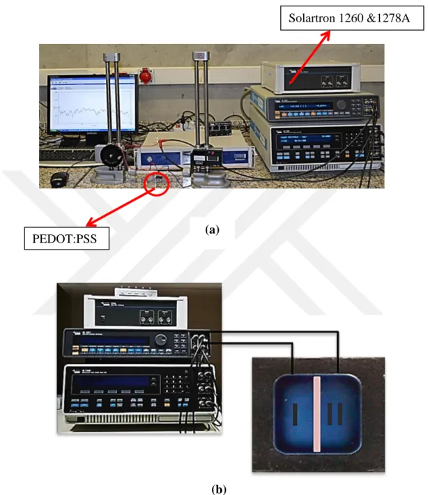
Figure 2.3: (a) Potensiostatic measurement set-up with Solartron 1260&1278A connected to CorrWare program (b) A closer image of sourcemeter connection to OEIP system..15
Figure 2.4: Four-point probe conductivity measurement connected to Keithley 2400 IV Sourcemeter………...………...17
Figure 2.5: Conductivity cell set-up system connected to Solartron 1260&1278A………..…...18
Figure 2.6: Inside structure of conductivity cell………...19
Figure 3.1: Difference between corona treated vs. non-treated PET substrates...22
Figure 3.2: FT-IR spectra of pure and overoxidized PEDOT:PSS………...23
Figure 3.3: Raman spectra for pristine and overoxidized PEDOT:PSS………...…...24
Figure 3.4: (a) 3D AFM images of pristine and overoxidized PEDOT:PSS substrates. After overoxidation the abraded the surface its roughness has increased vastly. (b) Contact angle measurements for electrochemically overoxidized, pristine and EG treated PEDOT:PSS substrates respectively………...25
Figure 3.5: Current vs. time graphs for (a) pristine and (c) EG treated PEDOT:PSS with KCl solution on side I and CaCl2 solution on side II of electrodes; Number of transported K+ ions for (b) pristine and (d) EG treated PEDOT:PSS...29 b
xii
Figure 3.6: Current vs. time measurements at different applied voltages between
two electrodes containing AChCl and KCl solutions oppositely for (a) pristine
(c) 2 hours EG treated (e) 6 hours EG treated (g) pH=1.5 and HCl acid treated
(i) pH=0.9 and HCl acid treated (k) electrochemically overoxidized region
Nafion™ treated PEDOT:PSS electrodes; Number of transported ACh+
ions at different applied voltages for (b) pristine (d) 2 hours EG treated (f) 6 hours
EG treated (h) pH=1.5 and HCl acid treated (j) pH=0.9 and HCl acid treated
(l) electrochemicalt overoxidized region Nafion™ treated PEDOT:PSS electrodes...31 Figure 3.7: Influence of electrical conductivity of electrodes on the
number of acetylcholine transported………...39 Figure 3.8: Equilibrium current densityvalues for OEIP with Prisitine and
Nafion™ treated overoxidized regions…………....………...40 (i)
xiii LIST OF TABLES
Page
Table 1.1: The effect of solvent additives to the conductivity of PEDOT:PSS……...6 Table 3.1: Performance of different substrates on OEIP production step………...21 Table 3.2: Surface roughness and contact angle values for pristine, overoxidized
and EG treated PEDOT:PSS. A significant change in surface roughness and contact angle is observed between electrochemically overoxidized and pristine PEDOT:PSS values which is due to change in surface energy...26
Table 3.3: Change in pH value of CaCl2 solution under various applied potential
values. The more molecules transport through the overoxidized region to the opposite side the more pH value changes………...27 Table 3.4: Change in conductivity values for pristine, overoxidized and EG
treated PEDOT:PSS………...38 Table 3.5: Enhancement in proton conductivity of electrochemically overoxidized
xiv
ABBREVIATIONS
OEIP : Organic Electronic Ion Pump
PEDOT:PSS :Poly(3,4-ethylenedioxythiophene)Polystyrenesulfonate PET : Poly(ethylene terepthalate)
PVC : Polyvinyl chloride
WHO : World Health Organization
AChCl : Acetylcholine Chloride
KCl : Potassium Chloride
CaCl2 : Calcium Chloride
UV : Ultraviolet
IPA : Isopropyl Alcohol
EG : Ethylene Glycol
NMP : N-methyl-2-pyrrolidone
DMSO : Dimethylsulfoxide
LiClO4 : Lithium perchlorate
IR : Infrared
FTIR : Fourier Transform Infrared
AFM : Atomic Force Microscope
RMS : Root Mean Square
xv
LIST OF SYMBOLS
The symbols used in this study are presented below along with their explanations.
σ Protonic Conductivity
ρ Resistivity
Ɩ Path Length Between Electrodes
A Cross sectional area available for protonic transport
Z’ Real part of impedance response
W Width of Sample
T Thickness of Sample
xvi
LIST OF EQUATIONS
Page Equation 2.1 Film Resistivity Calculations………...…....17 Equation 2.2 Proton Conductivity Calculation………...18 Equation 3.1 Evaluation of number of transported ions………...…...27
1 1. INTRODUCTION
1.1 Aim of the study
Taking into account the continuously developing neurological diseases and disorders, the following study aims to develop a certain way of curing it by using bioelectrical applications. By transfering the working principle of neuronal transport via neurotransmitter motion to laboratory scale, our self-developed system mimicks the same process by using a simple ion pump structure. We are also aiming to obtain maximum current and ion transfer with lowest applied driving force.
1.2 Motivation of the Study
Nerve cells are building blocks of our nervous system. Although they are classified as cells, their operation mechanism vastly differs from that of others. Nerve cells or in other words neurons are able to share information in-between by using electrochemical signals. This intracellular communication process is a chemical-electrical-chemical process that works due to the motion of ions. This inner communication induces our thoughts, motions, reactions and reflexes. The communicating part of the information-delivering cell is called presynaptic neuron and of the information, receiving cell is postsynaptic neuron. Although the communication is uninterrupted, the interesting fact is that these two cells never touch and this is why the messaging is called electro-chemical. The basic principle that lies behind that is the bunch of sequential chemical processes that involves motion of tiny macromolecules called neurotransmitters. Neurotransmitters diffuse across the synaptic cleft, a tiny gap between presynaptic and postsynaptic neuron, get linked to receptors on postsynaptic neuron and allows the headway of the information. When the transfer of neurotransmitters through synaptic cleft is disturbed or interrupted, this gives rise to some neurological disorders.[1] Diseases such as Alzheimer, epilepsy and
2
other physical disorders arise from the lack of specific neurotransmitter and their proper transport is what we are willing to obtain. According to statistical numbers reported by World Health Organization (WHO), in 2005 neurological disorders constituted 12% of total deaths globally. These values keep on constantly increasing and since neurological malfunctioning are such big threats to our world at the moment, a prevailing method of curing has to be developed. [1] Our study focuses on developing an effective solution to abnormalities in neural functioning, by designing a simple but potent structure that mimics the electro-chemical communication system similar to that of neurons. Here the main mission is to rehabilitate the transport of neurotransmitters through synaptic cleft and to further neural activity. Due to the recent advancements in the area of electrochemical flexible devices, the proposed structure for mimicking the electrochemical communication of neural cells was decided to be applied on conjugated polymers. Taking into account the fact that even conjugated polymers do not provide a very high conductivity, several precautions have been taken in order to provide proper current values.
1.3 Conductive Polymers and Ionomers
It is a known thing that polymers like plastics or rubbers have resistance to electrical conductivity and act as either dielectric materials or insulators. However, with the invention of polyacetylene, the very first conductive polymer, this idea has changed. From now on conductive polymers are receiving a great significance and interest in scientific and technological fields. Especially in the area of bioelectronics and polymer-based electronics the huge demand for these materials grows daily. The properties that make conductive polymers so attractive is that their electrical conductivity can be tailored with various doping levels. At the same time, these materials are highly flexible and thermally stable allowing their utilization in everyday applications. In some very popular fields like LEDs or supercapacitors, conductive polymers make a significant difference in performance over conductive metal oxides. The working principle of electrical charge flow in conductive polymers is generated as a result of electrical potential. Negatively charged electrons are driven towards the positive pole and generate current while passing from one atom to another. However, in
3
comparison to metal electrons, the electrons of polymers are not usually delocalized and their motion is much harder. While investigating the structure of most conductive polymers an alternating single-double bond pattern can be seen in Figure 1.1, which represents a conjugated backbone. [2] Here the double bonds known as pi bonds, strengthen connection between atoms by allowing the electron flow as a result of formation of delocalized orbitals. In this situation, the mobility of electrons can be enhanced via doping process in which number of electrons in polymer can be altered.
Figure 1.1 General structure representing conjugated conductive polymers
In addition to conductive polymers, there is one other class of polymers known as ionomers. An ionomer is a type of polymer containing ionic groups in its structure. In comparison to polyelectrolytes, which contain a large concentration of ionic groups, ionomers contain both normal repeating units and low concentration of ions on its backbone. In ionomer structures, nonpolar chains are gathered together while the polar ionic units have attraction in between. In case of presence of ionic groups in the backbone of polymer, some of its properties change seriously. Especially changes in viscosity, elastic modulus and glass transition temperatures are quite significant under heat application. [3]
C
C
C
n
4 1.4 PEDOT:PSS in Bioelectronics
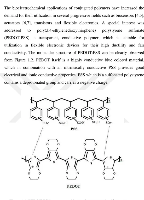
The bioelectrochemical applications of conjugated polymers have increased the demand for their utilization in several progressive fields such as biosensors [4,5], actuators [6,7], transistors and flexible electronics. A special interest was addressed to poly(3,4-ethylenedioxythiophene) polystyrene sulfonate (PEDOT:PSS), a transparent, conductive polymer, which is suitable for utilization in flexible electronic devices for their high ductility and fair conductivity. The molecular structure of PEDOT:PSS can be clearly observed from Figure 1.2. PEDOT itself is a highly conductive blue colored material, which in combination with an intrinsically conductive PSS provides good electrical and ionic conductive properties. PSS which is a sulfonated polystyrene contains a deprotonated group and carries a negative charge.
Figure 1.2 PEDOT:PSS structure with one deprotonated sulfone group
Thanks to their high conductivity and ductility, their utilization in electronic devices has grown vastly. Additionaly, in one of the studies conducted in this area it was proven that PEDOT:PSS provides a suitable environment for cell culture as well. All together these properties of PEDOT:PSS made this material
5
and indispensable part of bioelectronics which is why several methods have been proposed in order to properly incorporate PEDOT:PSS into bioelectrochemical systems. The main reason of PEDOT:PSS drawing so much attention is because it combines both ionic and electrical conductivity where PEDOT part serves for electrical conductivity of conjugated polymer while PSS offers ionic transport. System consists of selectively deposited PEDOT:PSS electrodes on poly(ethylene terepthalate) (PET) substrates with a tiny overoxidized region which serves as electrically insulating but ionically conductive part. [8].
1.5 Tailoring PEDOT:PSS Conductivity
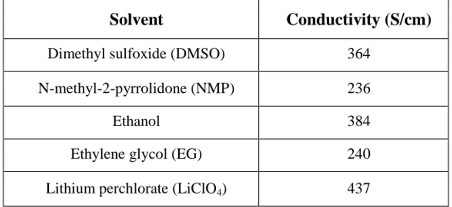
A large amount of investigations and researches are done in the field of PEDOT:PSS conductivity enhancement for the past few years. With the improvement in its conductivity, application area of PEDOT:PSS has developed equally. Although PEDOT:PSS itself has much better physical and electrical properties in comparison to other conductive polymers it still shows weaker and lower properties than metals and metal oxides. The enhancement of the conductivity of this conjugated polymer is reported to be done by organic compounds knowns as secondary dopants. Most of these organic compounds are ionic liquids, solvents containing polar groups, salts etc. The time of exposure of PEDOT:PSS to conductivity reinforcing additive is as important as the type of selected additive. Most of these additives effect the PEDOT:PSS structure by eliminating the PSS layer that provides ionic transport rather than electrical conductivity to the polymer composition. The most effective and highly powerful additives are N-methylpyroliddone (NMP), dimethylsulfoxide (DMSO), sorbitol, ethylene glycol (EG), methanol etc. Of course, solvent treatment is not the only method. Metal dopants such as lithium perchlorate (LiClO4) also succeed in conductivity enhancement.[9,10] According to most of
studies performed in this area the significant increase values of PEDOT:PSS electrical conductivity are given in Table 1.1.
6
Table 1.1 The effect of solvent additives to the conductivity of PEDOT:PSS
1.6 Flexible Electronic Substrates and Their Patterning Techniques
Flexible substrates also constitute a big part of electronic application in nowadays technology. Often named as flexible electronics, these devices are developed in order to assemble electronic systems on their surfaces and facilitate their utilization. Some of these substrates are well-known polyimide, polyether ether ketone (PEEK), polyester, polyethyleneterapthalate (PET) type polymers. These substrates are applicable in several areas where flexibility, easy production and space saving are the main concern. In addition, some of these substrates like PET are completely biocompatible and can be used in bioelectronic devices for human body. Most of recent studies done in this field utilized PET as substrate for bioelectrical circuits. The deposition of PEDOT:PSS on flexible substrates is suggested by various methods in literature. Processes like screen-printing, resist mask printing, UV lithography have been among the methods developed for PEDOT:PSS deposition on these substrates. Most of these methods are highly advanced and suitable for complex patterns. For instance, UV lithography also known as photolithography uses light to transfer the geometric configuration from the mask to photoresist on substrate. After a sequence of chemical treatment steps the remaining pattern enables the deposition of desired ink in relevant shapes. Screen-printing is another deposition technique, which has a simple application method. System consists of a mesh used to transfer ink on substrate. A squeegee, blade-like structure, moves along the screen, as shown in Figure 1.3, in order to fill the empty parts of mesh with ink and transfer the image to the substrate
Solvent Conductivity (S/cm) Dimethyl sulfoxide (DMSO) 364
N-methyl-2-pyrrolidone (NMP) 236
Ethanol 384
Ethylene glycol (EG) 240 Lithium perchlorate (LiClO4) 437
7
Figure 1.3 Schematic representation of screen-printing technique
Of course, many innovative and less effortless methods have been developed in comparison with UV lithography and screen-printing. One of these methods is line patterning method that we have used in our system for selective PEDOT:PSS deposition. [11-12]
Line patterning method, developed by MacDiarmid et al., is the most simple and economically available method of substrate patterning. The method consists of formation of negative of desired pattern via toner ink and depositing that ink on substrate by using printer. Method is simple as the formation of pattern is easily done by using computer-aided software programs. After pattern has been deposited, polymer solution can be injected on the empty parts of it via simple dropcast method. When the polymer solution dried on the surface completely, substrate may be sonicated in either toluene or acetone for approximately 10 seconds in order to get rid of toner ink. However, even in these developed methods several drawbacks such as tuning the photoresist thickness, time of exposition and development, reproducibility constantly occur. In some cases multiple steps of patterning processes hinder the massive production of these devices. Although this field of study is quite advanced, there are still some restrictions related to the performance of organic electronic devices for their low release rates, high voltage demands and limitations in design parameters. Therefore the preparation procedure of organic electronic ion pump (OEIP) from PEDOT:PSS for electronic control of ionic groups usually exchanged in neuronal cells is further improved in our laboratory.
8
In this study a straightforward but cost effective and time saving method called line patterning is used to selectively deposit PEDOT:PSS conjugated polymer on PET substrate at desired shapes required better ion pump performances. The reason of using line patterning method instead of other more utilized and recognized methods is that it is time saving and easy. The method is based on formation of a hydrophobic region leaving the desired shaped gap empty for further treatment. The toner ink forms homogeneous borders allowing the dropcasted ink to take the required shape. Several studies in the area of organic electronic devices have been done. Some of them are mainly based on the construction of OEIP, a delivery system designed to transfer ions from one subsystem to another via electrophoretic motion, thus mimicking the synaptic transfer in neural cells [12]. Schematic representation of OEIP is given in Figure 1.4.
Figure 1.4 Cross sectional image of electrodes I & II on PET substrate with liquid electrolyte of acetylcholine chloride and potassium chloride
The very first study performed in this area consisted of a 4 electrode system (A, B, C, D) from PEDOT:PSS of which 2 (A & D) serve as ion reservoirs and other (B & C) are serving as ion transfer borders. The middle region, which is chemically overoxidized, is 2mm wide and allows ion transport only. Conductivity measurements on system were done by filling the AB side of PEDOT:PSS electrode with KCl and CD side with CaCl2 solution. Under the
application of constant voltage, the ion transport through overoxidized region was measured. 1V potential difference was applied between A & B and C & D electrode groups that served as reservoirs for continuous K+ ions. Overoxidized region that resembles the synaptic cleft between two neuron endings provides ion transport only thus needs to be fully isolated from any electrical transport.
9
10V of potential is applied between electrodes B and C electrodes for this reason.
Another study performed in this field was focused on optimizing the previous configuration of OEIP by decreasing the number of PEDOT:PSS electrodes from 4 to 3 and narrowing the channelof ion transport. In that study instead of KCl solution, acetylcholine chloride (AChCl) solution was used. The purpose of this solution switch is because acetylcholine is the actual neurotransmitter. It is a macromolecule that is released because of Na+ - K+ ion exchange that generates action potential. The generating potential opens the Ca2+ channels through which calcium ions enter the neuron and release the ACh+ macromolecules from their saxes. Released acetylcholine ions electrophoretically transfer through synaptic cleft and reach the next neuron thus causing an electrochemical signalling. The new configuration came up with many advantages, such as the increase in current and ability to transfer macromolecules through a tiny channel. However, this was still not good enough since the system operated at 10V.
As we know, 10V is an extremely high potential difference, which cannot generate in human organism. That’s why our aim was to provide a configuration with better conditions under which ionic transport can occur under low applied potentials. Pristine PEDOT:PSS itself has a low conductivity that ranges between 0.38 - 2 S/cm. In some applications under low applied voltages, this conductivity is fair but not good to generate enough current. That’s why several other methods have been developed to increase the electrical and proton conductivity of PEDOT:PSS. It is even proven that proton conductivity of PEDOT:PSS is a more important parameter that should be considered while characterizing OEIP. Although no certain study focusing on proton conductivity of conjugated polymer has been investigated so far, it was decided to consider this in our study.
To sum up, main difference of our system from the ones used in previous studies is in some slight alterations done with the number and sizes of electrodes. Additionally, the whole process of OEIP formation was self made, while other studies were using prepared PEDOT:PSS deposited PET substrates from OrgaconTM. In order to achieve a homogeneous film throughout the substrate glycerol was suggested as an additive to PEDOT:PSS solution. Corona treatment of substrate also provided a stronger ink deposition. The durability of these films
10
to aqueous environments was also tested by keeping them in water for 24 hours. At the end of the test the overall structure remained unchanged with no rupture or damage on PEDOT:PSS film.
11
2. EXPERIMENTAL PROCEDURE
2.1 Materials
As the substrate of OEIP, polyethylene terephthalate (PET) and polyvinyl chloride (PVC) were selected as the most suitable ones for their being flexible, biocompatible and electrically insulating. The performance comparison was done between two of them in order to decide which one suits the operation conditions the best. PEDOT:PSS in granule form, ethylene glycol (EG), hydrochloric acid were purchased from Sigma Aldrich. Glycerol (Sigma Aldrich) was selected as an additive to PEDOT:PSS solution for promoting the better adhesion on PET substrate. Potassium chloride (KCl), calcium chloride (CaCl2) and acetylcholine chloride (AChCl) necessary for the potentiostatic
experiments were purchased from Sigma Aldrich as well. As the line patterning material standard printer toner was used. It is selected as the most appropriate material for tuning the surface wettability providing a hydrophobic region for holding off PEDOT:PSS solution. Isopropyl alcohol (IPA) and acetone were purchased from Sigma Aldrich and used as received.
2.2 Line Patterning and PEDOT:PSS Deposition
Before contouring the desired shapes on the substrate, they passed through one more step called air plasma treatment. Air plasma treatment or in other words corona treatment is a special technique used for surface modification by using corona discharge plasma. Under the application of high voltage, plasma is generated through the tip of device changing the surface energy of substrate providing an enhanced bonding during deposition. Without corona treatment, PEDOT:PSS solution could not cling strong enough on surface that’s why it was one of the most important steps in OEIP formation. Moreover, the durability of PEDOT:PSS to water also decreases without corona treatment. The treated PET
12
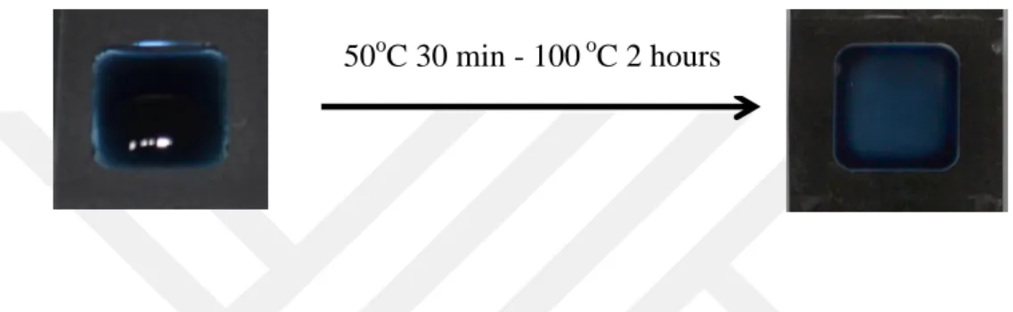
and PVC substrates ready to use were patterned with the printer toner forming the hydrophobic regions and allowing a determinate space for the ink to be injected [6,13]. The deposition of PEDOT:PSS (0.25 % w/w) solution on substrates was done by standard drop cast method on the area of 1.0 cm2. Due to the presence of hydrophobic phase on substrate, PEDOT:PSS solution diffuses to the available regions only taking the desired shape of pattern. The solution was dried on hot plate for 30 minutes at 50 °C and 2 hours at 100 °C as given in Figure 2.1.
Figure 2.1 Drop casting process of PEDOT:PSS aqueous solution on hot plate. The heating procedure starts with 50oC for 30 minutes and proceeds with 100oC for 2 hours
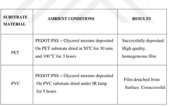
After overall deposition actualizes the electrochemical overoxidation step proceeds [14]. At this point, PET was selected as the substrate with better mechanical properties as PVC during the deposition step could not endure 100 °C and melted down. Additional solution was to dry PEDOT:PSS solution under IR red lamp. However, this also ended up in poor PEDOT:PSS clinging on substrate surface.
2.3 PEDOT:PSS Overoxidation
Overoxidation of PEDOT:PSS is an essential step in OEIP design. This step permanently cuts off the electrical conductivity of PEDOT phase making that part of system conductive to ions only. The region serves as a good ionic conductor leading to an easy transport of positively charged ions [7,14]. Under the effect of voltage, ions located on one side of electrochemically overoxidized region are transported through it to the opposite side.
13
PEDOT:PSS overoxidation was done by two methods: chemical and electrochemical method. For chemical overoxidation diluted sodium hypochlorite (0.01% NaClO) solution was dropped on the predetermined 2 mm region of PEDOT:PSS electrodes. This overoxidation step was difficult to control as the longer NaClO solution was kept on PEDOT:PSS the more it etched it from the surface. This was an undesired condition, as an undamaged PSS region should be left in order to provide ion transport. That is why electrochemical overoxidation method was proposed which is assumed safer, faster and easily controlled in comparison to chemical overoxidation achieved by sodium hypochlorite (Figure 2.2) [15-17].
Figure 2.2 Overoxidation step of PEDOT:PSS electrodes. A pre-determined 2 mm region is electrochemically overoxidized with 20% KCl solution via applied voltage
Samples were electrochemically overoxidized with a stainless steel wire as a counter electrode where approximately 15 V was applied between the KCl electrolyte solution and counter electrode. Since the overoxidation is done in a determinate region electrolyte solution is dropped directly to that part of PEDOT:PSS setting the boundaries with insulating polymers [15,17].
14 2.4 Potentiostatic Measurements
After constructing the OEIP properly, electrolyte solutions (KCl vs CaCl2 &
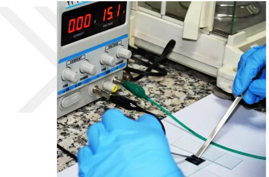
AChCl vs. KCl both 0.1M) were dropped on pre-determined opposing regions. Two trials were performed in these experiments. First tril included KCl and CaCl2 in order to test if the system works properly. This was not only tested by current values but also additional pH changes were recorded during experiment. Secondly, AChCl vs. KCl was tested again on the similar OEIP structure. pH recording was also performed at this stage. Under the effect of constant voltage positive ions (K+ and ACh+) passed through overoxidized region to the opposite electrode. As sourcemeter Solartron 1260 & 1278A was used to apply constant voltage and data were collected via CorrWare computer aided program (Figure2.3). Several potentials such as 1, 2, 5 and 10 V were applied for the electrodes I and II and current vs. time graphs were analyzed. Counter electrode was connected to K+ and working electrode was connected ACh+ side and as a result positive ions were driven through electrochemically overoxidized region.
2.5 Fourier Transform Infrared (FTIR) and Raman Spectroscopy
It was assumed that the electrochemical overoxidation of PEDOT:PSS as a result lead to cutting off the electrical conductivity of overall conjugated polymer which would end up in significant changes in its chemical structure [17]. In order to reassure that overoxidation actually took place several spectroscopic methods were used. First analyses were performed by the Fourier Transform Infrared (FTIR) measurements (Perkin Elmer Spectrum 100). The principle of FTIR is based on measuring how good substance absorbs light at each wavelength and gives out the response in spectrum form. Based on the peak intensity and wavenumber the change in structure or possible interaction is concluded. Another characterization technique for the electrochemical overoxidized region of PEDOT:PSS was the Raman spectroscopy (Renishaw, Invia) which was expected to show the main peak shifts prior to and after electrochemical overoxidation steps [18]. Similar to FTIR, Raman also operates on the principle of light absorbance. However, Raman is a more specific
15
spectroscopic technique by which the molecule can be identified. Raman measurements were performed with 532 nm Ar-ion laser.
Figure 2.3 (a) Potensiostatic measurement set-up with Solartron 1260&1278A connected to CorrWare program (b) A closer image of sourcemeter connected to OEIP system. Working electrode is connected to ACh+ (or K+ in case of CaCl2
experiment) side since similar poles repel each other PEDOT:PSS
Electrode
Solartron 1260 &1278A
(a)
16 2.6 AFM and Contact Angle Measurements
Together with structural changes of PEDOT:PSS after overoxidation, some specific changes in its physical properties were also expected. In order to understand this two more spectroscopic tests were performed. One of them is Atomic Force Microscope (AFM), a device where a tiny 10 nm tip scans a defined area and translates signals to give out the final image of surface. This method is highly popular and has three main operation modes, which are contact mode, non-contact mode and tapping mode. For our AFM measurements, Asylum MFP-3D was used on tapping mode. Another measurement for surface change identification was selected as contact angle measurement performed on OneAttension contact angle device. Its working principle is based on recording the image of water (or any other desired fluid) droplet touching the substrate surface and measuring its angle of contact with surface. The computer aided program gives out the immediate result.
2.7 Conductivity Enhancement
Once the standard potentiostatic tests have been performed, several methods were developed in order to strengthen the electrical and proton conductivity of PEDOT:PSS. As the first method, EG, NMP, methanol vapor and LiClO4
treatment methods were selected. Dropwise added EG on PEDOT:PSS electrodes were kept at different time intervals of 2, 6, 12 and 24 hours. After EG treatment, samples were annealed at 100oC for 1 hour under vacuum in order to get rid of excess EG left on surface. Similar to EG treatment, NMP and methanol treatment was also tried. Samples were kept in NMP and Methanol separately for 2, 6 and 24 hours. Post-annealing was also applied on these substrates. A different type of conductivity enhancement was done by using LiClO4 solid into PEDOT:PSS solution. After stirring the solution overnight
mixture was dropcasted on OEIP structure. An additional technique to conductivity enhancement was selected as acid treatment. The pH of pristine PEDOT:PSS solution was measured and found to be 0.38 S/cm. It was assumed that the decrease in pH value of solution would increase its conductivity. That is why the pH value of solution was arranged with hydrochloric acid to pH=1.5
17
and pH=0.9. Electrical conductivities of OEIPs after above mentioned treatments were measured by using 4-point probe resistivity measurement device equipped with Keithley 2400 IV Sourcemeter (Figure 2.4). The working principle of 4-point probe is based on a fixed applied current between 2 out probes and voltage that is measured between other 2 inner probes. The obtained resistivity value must be converted to resistance with following formula. Thus, the 1/Rs gives us
conductivity value.
⁄
⁄
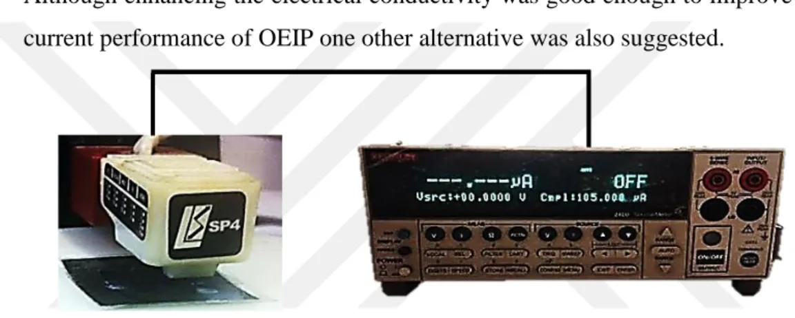
Although enhancing the electrical conductivity was good enough to improve the current performance of OEIP one other alternative was also suggested.
Figure 2.4 Four-point probe conductivity measurement connected to Keithley 2400 IV Sourcemeter
Taking into the fact that Acetylcholine molecules transfer through the overoxidized region by exchanging charges with PSS group of conjugated polymer, addition of an extra ion-conductive layer was suggested. NafionTM aqueous solution (5% v/v) was dropcasted on electrochemically overoxidized region of OEIP and dried under IR lamp until a homogeneous film forms. The effect of additional NafionTM layer on OEIP performance was measured with conductivity cell and standard conductivity measurements via Solartron 1260 & 1278A. Conductivity cell contains 4-electrodes to which the material to be tested is attached. The main advantage of 4-electorde system is that the resistance is measured based on charge transport only. All other resistances such as interfacial or charge transfer are not included in these measurements.
18
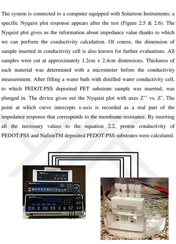
The system is connected to a computer equipped with Solartron Instruments; a specific Nyquist plot response appears after the test (Figure 2.5 & 2.6). The Nyquist plot gives us the information about impedance value thanks to which we can perform the conductivity calculation. Of course, the dimension of sample inserted in conductivity cell is also known for further evaluations. All samples were cut at approximately 1.2cm x 2.4cm dimensions. Thickness of each material was determined with a micrometer before the conductivity measurement. After filling a water bath with distilled water conductivity cell, to which PEDOT:PSS deposited PET substrate sample was inserted, was plunged in. The device gives out the Nyquist plot with axes Z’’ vs. Z’. The point at which curve intercepts x-axis is recorded as a real part of the impedance response that corresponds to the membrane resistance. By inserting all the necessary values to the equation 2.2, proton conductivity of PEDOT:PSS and NafionTM deposited PEDOT:PSS substrates were calculated.
Figure 2.5 Conductivity cell set-up system connected to Solartron 1260&1278A. OEIP system inserted into conductivity cell is plunged into deionized water bath for measurement
A
Z
l
'
(2.2)
19
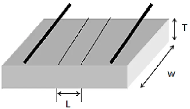
Figure 2.6 Inside structure of conductivity cell. L represents the distance between two side electrodes; W and T are the width and thickness of samples.
21 3. RESULTS AND DISCUSSION
3.1 PEDOT:PSS Deposition and Substrate Selection
The comparison between PVC and PET substrates was done according to their behavior at high temperatures and the degree of PEDOT:PSS clinging. Both substrates were cleaned with acetone, isopropanol (IPA) and distilled water before being patterned. PET was selected as the substrate with best performance and overall analysis of both of materails are given in Table 3.1
Table 3.1 Performance of different substrates on OEIP production step. PET and PVC were compared for their heat durability and ink clinging degree
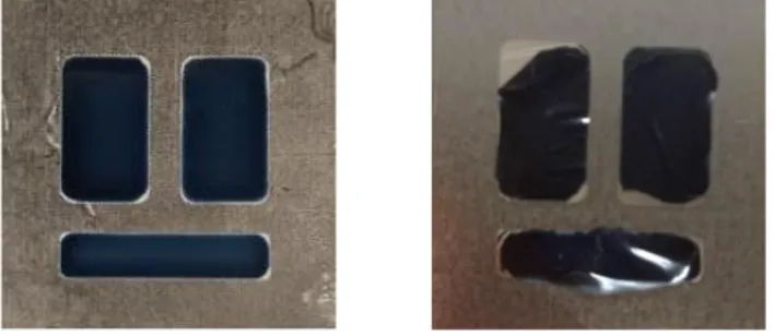
The deposition of PEDOT:PSS on flexible PET substrate at pre-determined shapes was done by line patterning method followed by drop casting [18]. An important parameter playing a crucial role at this step is corona treatment that provides an enhanced adhering of conjugated polymer on substrate by modifying the surface energy. The images of corona treated versus corona non-treated PEDOT:PSS deposited on PET substrate are given in Figure 3.1 The
SUBSTRATE MATERIAL AMBIENT CONDITIONS RESULTS PET
PEDOT:PSS + Glycerol mixture deposited On PET substrate dried at 50oC for 30 min. and 100 oC for 3 hours
Successfully deposited. High quality,
homogeneous film
PVC
PEDOT:PSS + Glycerol mixture deposited On PVC substrate dried under IR lamp for 5 hours
Film detached from Surface. Unsuccessful
22
difference in adhesion is clearly seen between two images. As a result defect free well-adhered samples were successively achieved after surface treatment by corona. Overoxidation in this study was successfully achieved electrochemically.
Figure 3.1 Difference between corona treated vs. non-treated PET substrates
3.2 Characterization of OEIP
Spectra obtained from FTIR measurements were analyzed and significant differences were observed due to the electrochemical overoxidation. It is obvious from the Figure 3.2 that prior to overoxidation there is no peak on pure PEDOT:PSS spectra while a prominent peak occurs after overoxidation. The peak occurring close to 1720 cm-1 corresponds to C=O stretching, while double-head peaks in 1175 cm-1 wavenumber range attributes to sulfonate group (S=O) stretching. These peaks in FT-IR spectra explain the lowering of the electrical conductivities of PEDOT:PSS to about 0.06 S cm-1. According to previous studies done in this area, this change corresponds to the formation of carbonyl groups on thiophene rings that cuts off the conjugation in chain [18,19]. Remaining chemical structure then becomes electrically insulator, but ionically conductive due to the polystyrene sulfonate groups (PSS).
Raman spectra of pristine and electrochemically overoxidized PEDOT:PSS are given in Figure 3.3 There is a visible peak shift at approximately wavenumber of 1430 cm-1 which corresponds to symmetric C=C stretching of thiophene ring [19-22]. After the electrochemical overoxidation step, this peak shifts slightly towards 1450 cm-1 proving the oxidized state of the PEDOT:PSS. In the previous studies, this type of change in wavenumber and peak intensity increase was correlated to the transformation of resonance structure of
23
thiophene backbone. Enhanced peaks at 1500 and 1570 cm-1 are also reported as asymmetric stretching vibrations of thiophene ring of PEDOT:PSS in the middle and at the end of chains.
A significant change in surface topography of PEDOT:PSS was expected after the electrochemical overoxidation. AFM Imaging was selected as the most proper method for determining the surface roughness values. The root mean square (RMS) surface roughness, Rq, of pristine PEDOT:PSS at 500 nm scaling in AFM were reported in Table 3.2 and shown in Figure 3.4. Pristine PEDOT:PSS films appear to be highly homogeneous with extremely low roughness values. Due to the electrochemical overoxidation surface was resulted with high roughness overall. Together with AFM results, the change in surface morphology was proven by performing contact angle measurements [22]. A pristine, overoxidized and ethylene glycol treated PEDOT:PSS by using simple contact angle method were tested and eventually the change in surface energy was interpreted. According to contact angle measurements, hydrophilicity of surface highly increases after electrochemical overoxidation step. This may correspond to the decrease in surface energy after electrochemical overoxidizing PEDOT:PSS. Therefore, overoxidized region becomes more hydrophilic with the lower surface energy enhancing the aqueous ionic transport from electrode I to II.
Figure 3.2 (a) FT-IR spectra of pure and overoxidized PEDOT:PSS.
800 1000 1200 1400 1600 1800 88 92 96 100 T% Wavenumber (cm-1) pristine pedot:pss overoxidized pedot:pss (a)
24
Figure 3.2 continues The most significant peak shifts represent (b) S=O stretching at 1175 cm-1 and (c) 1720 cm-1 C=O stretching
Figure 3.3 Raman spectra for pristine and overoxidized PEDOT:PSS. Peaks at 1430 cm-1 corresponds to characteristic C=C stretching of thiophene ring, which shifts and intensifies after overoxidation step.
1700 1720 1740 1760 99 100 T% Wavenumber (cm-1) pristine pedot:pss
electrochemically overoxidized pedot:pss
(b)
(b)
0 600 1200 1800 2400 3000 0 20000 40000 6000080000 Pristine PEDOT:PSS Overoxidized PEDOT:PSS
In te ns ity Raman shift cm-1 (c) 1140 1160 1180 1200 99 100 T% Wavenumber (cm-1) pristine pedot:pss
electrochemically overoxidized pedot:pss
(a)
1350 1400 1450 1500 1550 1600 (b)
25
Figure 3.4 (a) 3D AFM images of pristine and overoxidized PEDOT:PSS substrates. After overoxidation the abraded the surface its roughness has increased vastly. (b) Contact anlge measurements for electrochemically overoxidized, pristine and EG treated PEDOT:PSS substrates respectively
(b) (a)
26
Table 3.2 Surface roughness and contact angle values for pristine, overoxidized and EG treated PEDOT:PSS. A significant change in surface roughness and contact angle is observed between electrochemically overoxidized and pristine PEDOT:PSS values which is due to change in surface energy.
3.3 Potentiostatic Measurements and Conductivity Enhancement
Several conductivity measurements were done on PEDOT:PSS electrodes. Most of them involved the presence of ACh+ ions as the main aim was to provide the transport of neurotransmitter through the overoxidized region. However, at first steps in order to test the system KCl vs. CaCl2 tests were performed (Figure 3.5).
Afterwards, to understand the effect of additives on electrical conductivity of system similar potensiostatic measurements were repeated in Solartron 1260&1278A. In order to understand clearly the transfer of molecules through the overoxidized region current density values are not enough. pH and number of transported ion measurements were also performed for this reason (Table 3.3). By applying constant voltage for 1800 seconds, the transfer of K+ ions through overoxidized region is expected to change the pH of CaCl2 solution. At the end
of the experiment, solution on side II of OEIP structure is tested with pH strips. Same experiment was also performed on systems containing ACh+ vs. K+.
Material Av. Contact Angle (Degree) Surface Roughness (nm) Overoxidized PEDOT:PSS 9.10 43.5 Pristine PEDOT:PSS 56.53 5.34
27
Table 3.3 Change in pH value of CaCl2 solution under various applied potential
values. The more molecules transport through the overoxidized region to the opposite side the more pH value changes
Additionally, to understand the number of ions transported to the opposite side of overoxidized region several calculations have to be done. In order to do that first we need to obtain charge values from the current density data. As we know, current (Ampere) is the flow rate of charge (Coulomb). Here current can also be interpreted as the amount of charges passing through a certain point in a second. Thus, in order to obtain charge from current values the integration of current data has to be done. This is performed by a well-known “Cumulative trapezoidal numerical integration” CUMTRAPZ function in MATLAB2013 computer aided software. As a result, matlab performs an integration of all current values with respect to time and gives out the charge values. However, our ultimate purpose is to obtain number of transported ions and to do this a simple calculation is performed.
By instering the value of charge into the formula, the number of transported ions can be calculated. Calculations were performed on Microsoft Excel 2010 and MATLAB 2013 softwares. In previous studies performed in the area of the conductivity enhancement of PEDOT:PSS, several additives and/or thermal annealing processes have been well investigated [24-28]. Ethylene glycol (EG) in this study was utilized for the conductivity enhancement experiments as other additives failed in conductivity enhancement. The period of OEIP exposure to
Applied Potential (V) pH change
1 From 7 to 4
2 From 7 to 3
5 From 7 to 2
10 From 7 to 2
28
either NMP or methanol did not change the conductivity value or cause any other significant increase. Similarly, addition of LiClO4 to the PEDOT:PSS
solution ended up in poor surface adhesion. As a result of heating after dropcasting, LiClO4 particles came out on the surface in form of white film. No
valuable conductivity change was observed in this method as well. The reason of failure of these additives in our conductivity strengthening trials was related to the type of PEDOT:PSS we used. In comparison to other studies where high conductivity grade PEDOT:PSS viscous solutions were used, in our study PEDOT:PSS bead-like particles were dissolved in water and mixed with glycerol. Thus, this may have probably changed the composition and properties of conjugated polymers. However, a considerable change in conductivity was observed in EG treatment. Moreover, it was observed that the time of exposure of PEDOT:PSS films to EG had a prominent effect as well. While a 2 hour exposure increased the conductivity value by approximately 5 folds, a 6 hour treatment has changed the conductance values by almost 21 folds. Thus, exposing the electrodes I and II to EG solution, the conductivities of the electrodes were expected to increase, while the electrochemically overoxidized part was left unaffected. The explanation of increasing the electrical conductivity of PEDOT:PSS electrodes lies under the fact that EG abolishes the PSS phase that accounts for ionic transfer thus leaving the polymer film with remaining electrical conduction [17]. This way, ions could be driven faster towards the overoxidized region speeding up the overall transfer [30-32]. The conductivities of EG treated, pristine and electrochemically overoxidized PEDOT:PSS were measured with 4-point probe resistivity measurement method. After applying a sweep voltage between -1 and +1V via Keithley 2400 IV Sourcemeter current vs. voltage data sets were obtained and as a result resistivity values could be evaluated. The effect of EG treatment time on the conductivities of PEDOT:PSS electrodes was also tested. For this purpose, PEDOT:PSS electrodes were exposed to EG for 2, 6, 12 and 24 hours for tailoring the electrical conductivities of them. A significant increase from 0.38 S/cm to 8 S/cm was noticed under the exposure of 6 hours while no noticeable change was observed after 2 hours of ethylene glycol treatment. However, the conductivity increase stabilized after 6 hours of treatment along further 24 h.
29
Figure 3.5 Current vs. time graphs for (a) pristine and (c) EG treated PEDOT:PSS with KCl solution on side I and CaCl2 solution on side II of electrodes; Number of transported K+ ions for (b) pristine and (d) EG treated PEDOT:PSS 0 300 600 900 1200 1500 1800 0 20 40 60 80 Cu rr en t Dens ity ( A cm -2 ) Time (s) 1V 2V 5V 10V 0 300 600 900 1200 1500 1800 0 8x10¹⁵ 2x10¹⁶ 2x10¹⁶ 3x10¹⁶ 4x10¹⁶ Numb er of K + trans ported Time (s) 1V 2V 5V 10V (a) (b) (a)
30
Figure 3.5 continues Current vs. time graphs for (a) pristine and (c) EG treated PEDOT:PSS with KCl solution on side I and CaCl2 solution on side II of electrodes; Number of transported K+ ions for (b) pristine and (d) EG treated PEDOT:PSS 0 300 600 900 1200 1500 1800 0 20 40 60 80 100 120 Cu rr en t Dens ity ( A cm -2 ) Time (s) 1V 2V 5V 10V 0 300 600 900 1200 1500 1800 0 3x10¹⁷ 6x10¹⁷ 9x10¹⁷ 1x10¹⁸ Numb er of K + transp orted Time (s) 1V 2V 5V 10V (c) (d)
31
Another additional method for conductivity enhancement of PEDOT:PSS was selected as pH drop with the hydrochloric acid treatment. Whilst the pristine PEDOT:PSS solution have a pH value of nearly 4.5, by decreasing this value to 1.5 and lower to 0.9 a significant increase is also seen in the conductivity values which can be summarized in Table 3.4. As previously mentioned, the performance of OEIP was tested at various applied potentials between two electrodes. Therefore, the system was tested at 1V, 2V, 5V and 10V and current vs. time graphs were obtained (Figure 3.6). Application of OEIP is aimed for utilization it in bioelectrochemical devices. For this reason, its ability to transfer of macromolecules such as neurotransmitters gives us a better understanding of performance of OEIP later in vivo experiments. Under varying voltage values the amount of current and charge passing through the overoxidized region was measured. Acetylcholine transport has been monitored by the equilibrium current density, which indicates the rate for drifting of the acetylcholine ions from electrode I to electrode II values at several potentials (Figure 3.6).
Figure 3.6 Current vs. time measurements at different applied voltages between two electrodes containing AChCl and KCl solutions oppositely for (a) pristine (c) 2 hours EG treated (e) 6 hours EG treated (g) pH=1.5 and HCl acid treated (i) pH=0.9 and HCl acid treated (k) electrochemically overoxidized region Nafion™ treated PEDOT:PSS electrodes; Number of transported ACh+ ions at different applied voltages for (b) pristine (d) 2 hours EG treated (f) 6 hours EG
0 300 600 900 1200 1500 1800 0 50 100 150 200 250 300 Cu rrent Den sit y ( A cm -2 ) Time (s) 1V 2V 5V 10V (a)
32
treated (h) pH=1.5 and HCl acid treated (j) pH=0.9 and HCl acid treated (l) electrochemically overoxidized region Nafion™ treated PEDOT:PSS electrodes
Figure 3.6 Current vs. time measurements at different applied voltages between two electrodes containing AChCl and KCl solutions oppositely for (a) pristine (c) 2 hours EG treated (e) 6 hours EG treated (g) pH=1.5 and HCl acid treated (i) pH=0.9 and HCl acid treated (k) electrochemically overoxidized region Nafion™ treated PEDOT:PSS electrodes; Number of transported ACh+ ions at
0 300 600 900 1200 1500 1800 0 2x10¹⁶ 4x10¹⁶ 6x10¹⁶ Nu mber of ACh + t ransported Time (s) 1V 2V 5V 10V 0 300 600 900 1200 1500 1800 0 50 100 150 200 250 300 Cu rrent Den sit y ( A cm -2 ) Time (s) 1V 2V 5V 10V (c) (b)
33
different applied voltages for (b) pristine (d) 2 hours EG treated (f) 6 hours EG treated (h) pH=1.5 and HCl acid treated (j) pH=0.9 and HCl acid treated (l) electrochemically overoxidized region Nafion™ treated PEDOT:PSS electrodes
Figure 3.6 Current vs. time measurements at different applied voltages between two electrodes containing AChCl and KCl solutions oppositely for (a) pristine (c) 2 hours EG treated (e) 6 hours EG treated (g) pH=1.5 and HCl acid treated (i) pH=0.9 and HCl acid treated (k) electrochemically overoxidized region Nafion™ treated PEDOT:PSS electrodes; Number of transported ACh+ ions at
0 300 600 900 1200 1500 1800 0 7x10¹⁶ 1x10¹⁷ 2x10¹⁷ 3x10¹⁷ Nu mber of ACh + t ransported Time (s) 1V 2V 5V 10V 0 300 600 900 1200 1500 1800 0 30 60 90 120 150 180 Cu rrent Den sit y ( A cm -2 )
Time (s)
1V 2V 5V 10V (e) (d)34
different applied voltages for (b) pristine (d) 2 hours EG treated (f) 6 hours EG treated (h) pH=1.5 and HCl acid treated (j) pH=0.9 and HCl acid treated (l) electrochemically overoxidized region Nafion™ treated PEDOT:PSS electrodes
,
Figure 3.6 Current vs. time measurements at different applied voltages between two electrodes containing AChCl and KCl solutions oppositely for (a) pristine (c) 2 hours EG treated (e) 6 hours EG treated (g) pH=1.5 and HCl acid treated (i) pH=0.9 and HCl acid treated (k) electrochemically overoxidized region
0 300 600 900 1200 1500 1800 0 1x10¹⁷ 2x10¹⁷ 3x10¹⁷ 4x10¹⁷ 5x10¹⁷ Nu mber of ACh + t ransported Time (s) 1V 2V 5V 10V 0 400 800 1200 1600 0 50 100 150 200 250 300 350 400 Cu rrent Den sit y ( A cm -2 ) Time (s) 1V 2V 5V 10V (f) (g)
35
Nafion™ treated PEDOT:PSS electrodes; Number of transported ACh+ ions at different applied voltages for (b) pristine (d) 2 hours EG treated (f) 6 hours EG treated (h) pH=1.5 and HCl acid treated (j) pH=0.9 and HCl acid treated (l) electrochemically overoxidized region Nafion™ treated PEDOT:PSS electrodes
Figure 3.6 Current vs. time measurements at different applied voltages between two electrodes containing AChCl and KCl solutions oppositely for (a) pristine (c) 2 hours EG treated (e) 6 hours EG treated (g) pH=1.5 and HCl acid treated (i)
0 300 600 900 1200 1500 1800 0 1x10¹⁷ 2x10¹⁷ 3x10¹⁷ 4x10¹⁷ 5x10¹⁷ Nu mber of ACh + t ransported Time (s) 1V 2V 5V 10V 0 300 600 900 1200 1500 1800 0 50 100 150 200 250 300 350 Cu rrent Den sit y ( A cm -2 ) Time (s) 1V 2V 5V 10V (h) (i)
36
pH=0.9 and HCl acid treated (k) electrochemically overoxidized region Nafion™ treated PEDOT:PSS electrodes; Number of transported ACh+ ions at different applied voltages for (b) pristine (d) 2 hours EG treated (f) 6 hours EG treated (h) pH=1.5 and HCl acid treated (j) pH=0.9 and HCl acid treated (l) electrochemically overoxidized region Nafion™ treated PEDOT:PSS electrodes
Figure 3.6 Current vs. time measurements at different applied voltages between two electrodes containing AChCl and KCl solutions oppositely for (a) pristine (c) 2 hours EG treated (e) 6 hours EG treated (g) pH=1.5 and HCl acid treated (i)
0 300 600 900 1200 1500 1800 0 1x10¹⁷ 2x10¹⁷ 3x10¹⁷ 4x10¹⁷ 5x10¹⁷ Nu mber of ACh + t ransported Time (s) 1V 2V 5V 10V 0 300 600 900 1200 1500 1800 0 300 600 900 1200 1500 Current Dens it y ( Acm -2 ) Time (s) 1V 2V 5V 10V (j) (k)