Ferroelectric Based Tuneable SRR Based
Metamaterial for Microwave Applications
Ekmel Ozbay1,*, Koray Aydin1, Serkan Butun1, Katarzyna Kolodziejak2, and Dorota Pawlak2
1NanotechnologyResearch Center, Department of Physics and Department of Electrical and Electronics Engineering, Bilkent University 06800 Bilkent, Ankara, TURKEY
2Institute of Electronic Materials Technology, Warsaw, Poland
Abstract
—
We discuss the possibility of achieving tunable splitring resonators at microwave frequencies. One method is to use varying capacitance values to tune the magnetic resonance frequency. As another method ferroelectric thin films can be employed to obtain active response from the split ring resonators. We report the experimental measurements that are performed for single split ring resonators at microwave frequencies.
I. INTRODUCTION
Split ring resonator (SRR) structures are commonly used in left-handed metamaterial studies, since they provide negative values of magnetic permeability near the magnetic resonance frequency. SRR structure consists of two concentric rings separated by a gap, both having splits oriented at opposite sides with respect to each other. Magnetic resonance is induced by the splits at the rings and by the gap between the inner and outer rings. Resonance frequency is determined the total capacitance and the inductance of the resonator system. Thus, it is possible to tune the magnetic resonance frequency (ωm) of SRRs by changing the capacitance of the system
[1-15].
II. CAPACITOR-LOADED SPLIT-RING RESONATORS
SRRs can be modelled as LC circuits where the inductance arises from the rings. Total capacitance of the SRR system has mainly two contributions. The first one is the capacitance at the split regions and the second contribution is from the gap between the concentric rings. These capacitances together with the inductances from the rings, determine the ωm of the
resonator structure. Changing the capacitance and inductance values results in a change in ωm of SRRs, as expected from an
LC circuit [8].
Split-ring resonator structures are built from nonmagnetic concentric copper rings with splits oriented at the opposite sides. Figure 1(a) shows a schematic drawing of a single SRR. The structural parameters, as provided in Fig. 1(a), are
d=t=0.2 mm, w=0.9 mm and R=3.6 mm [16]. Planar SRR
array is fabricated on FR4 printed circuit boards and unit cells of SRRs are extracted from the array. Surface mount capacitors with various capacitance values are placed at three different capacitive regions of SRRs. Namely, (i) the gap region between inner and outer rings, (ii) outer ring’s split region and (iii) inner ring’s split region. The photographs of the SRRs loaded with capacitors are given in the insets of Fig. 2(a), (b) and (c), respectively.
Fig. 1 (a) Schematic picture of a single split ring resonator, (b) Photograph of experimental setup for measuring transmission coefficients.
The resonance behaviour could be observed from the frequency response of single SRR. Two monopole antennas are used to transmit and detect the EM waves through the single SRR unit cell. The monopole antenna was constructed by removing the shield around one end of a microwave coaxial cable. The exposed center conductor which also acted as the transmitter and receiver was on the order of λ/2, arranged to work at the frequency range covering the ωm of
the SRR structures.
Fig. 2. SRR with capacitor loaded (a) in the gap region between concentric rings, (b) in the outer split region, and (c) in the inner split region.
978-2-87487-001-9 © 2007 EuMA October 2007, Munich Germany
Proceedings of the 37th European Microwave Conference
A single SRR is placed between the monopole antennas as shown in Fig. 1(b). The distance between the monopole and SRR unit cell is 6 mm. Monopole antennas are then connected to the HP-8510C network analyzer to measure the transmission coefficients. First we measured the transmission spectra in free space (i.e. without SRR unit cell) which is used as the calibration data for the network analyzer. Then, SRR unit cell was inserted between the monopole antennas, and we performed the transmission measurements by maintaining distance between the transmitter and receiver monopole antennas fixed.
We mounted capacitors at three different capacitive regions of SRRs’ namely, outer split, inner split and the gap between the rings [16]. The results are provided in Fig. 3. The data points are the corresponding resonance frequencies for the capacitors loaded at respective regions. The solid lines are the numerical model results. As a comparison, ωm shifted down to
2.86 GHz with a 3.3 pF capacitor loaded at the gap region. But same amount of tuning has been achieved with a 0.1 pF capacitor at the split region of the outer ring. To reduce ωm
down to 2.86 GHz, a capacitor with capacitance value between 0.2-0.4 pF is required to be loaded at the inner ring’s split region. The highest tunability range is achieved with capacitors at the outer ring’s split region.
Fig. 2 Magnetic resonance frequency of a split ring resonator as a function of loaded-capacitances at different capacitive regions. Solid lines are the results obtained from the numerical models.
It is worth mentioning at this point that by loading capacitor at the split region of the outer ring with a value of
C=2.2 pF, we managed to obtain ωm at 0.99 GHz. To our
knowledge, this is the highest reduction of resonance frequency of SRR. The diameter of the SRR structure is 7.2 mm and the free-space wavelength at 0.99 GHz is 303 mm. Therefore magnetic resonance is achieved by using a subwavelength structure with a size of λ/42.
III. FERROELECTRIC THIN FILMS AS SRR SUBSTRATES Ferroelectricity is the property of certain non-conducting crystals, or dielectrics, that show spontaneous electric polarization. This can be reversed in direction by the applying an electric field. Ferroelectric materials undergo a structural phase transition over a range of temperatures. The temperature at which this transition occurs is known as the Curie temperature, Tc. Below the Curie temperature the material exists in the ferroelectric (polar) phase and above the Curie temperature it is in the paraelectric state
The effect of spontaneous electrical polarization under an applied electrical field results in a rapid change of the material’s dielectric permittivity (ε’). Dielectric permittivity of ferroelectric materials does also change with the change in temperature.
In this study we used ferroelectric thin films to tune the magnetic resonance frequency of SRRs. Ferroelectric thin films are usually >1 µm thick films deposited on a substrate. Ferroelectric thin films vary in operation temperatures and types ferroelectric materials used. Operation temperatures of ferroelectric thin films have a wide range. But most of the ferroelectric thin films operate below room temperature. Barium strontium titanate (BSTO) is a promising material for microwave applications. To obtain the optimum performance of such devices it is critical to maximize the dielectric tunability (n), i.e., the ratio of the permittivity at zero electric field to the permittivity at a defined field, and to minimize the dielectric loss (tan δ) in the device’s operational frequency range. Curie temperature (TC) and tunability of BSTO films is
a strong function of Ba/Sr ratio. The tunability is achieved by varying the dielectric permittivity of ferroelectric thin film with the temperature.
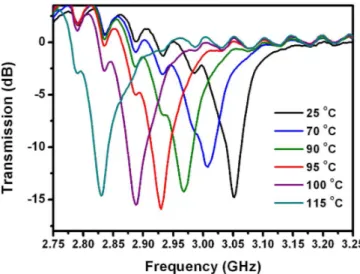
Fig. 4. Measured transmission spectra of single SRRs covered with ferroelectric thin film. Temperature is varied between 25-115 oC. Magnetic resonance frequency shifts downwards with an increase at the temperature.
The ferroelectric thin film that we use in the experiment is a 1 µm thick BSTO film deposited on a 0.5 mm alumina substrate. We have stacked ferroelectric thin film with the
SRR structure. SRR structure is composed of a 1.6 mm PCB dielectric board and 30 µm copper SRR layer. Ferroelectric thin film is in contact with the copper SRR layer.
We have increased the temperature of the sample and measured the transmission through the sample. The magnetic resonance frequency has been shifted to lower frequencies with increasing temperature as seen in Fig. 4. We have achieved a 0.22 GHz tuning range, between 2.83-3.05 GHz. At room temperature measured resonance frequency was 3.05 GHz. We have heated the sample up to 115 oC and at that temperature the resonance frequency is 2.83 GHz.
The tunability is achieved by varying the dielectric permittivity of ferroelectric thin film with the temperature. The next step is to deposit SRR structures on ferroelectric thin films and achieve tunability by applying voltage.
IV. CONCLUSIONS
To summarize, we have experimentally demonstrated the possibility of tunable split-ring resonators at microwave frequencies by using two methods: 1- Using loaded capacitors to change the magnetic resonance frequency of SRRs, 2- Depositing SRR on ferroelectric thin films.
ACKNOWLEDGMENT
This work is supported by the European Union under the projects METAMORPHOSE, EU-NoE-PHOREMOST, and TUBITAK under Projects Nos. 104E090, 105E066, 105A005, and 106A017. One of the authors (E.O.) also acknowledges partial support from the Turkish Academy of Sciences.
REFERENCES
[1] J. B. Pendry, A. J. Holden, D. J. Robbins, and W. J. Stewart, “Magnetism from conductors and enhanced nonlinear phenomena,” IEEE Trans. Microwave Theory Tech, vol. 47, pp. 2075–2081, 1999.
[2] D. R. Smith, W. J. Padilla, D. C. Vier, S. C. Nemat-Nasser, and S. Schultz, “Composite medium with simultaneously negative permeability and permittivity,” Phys. Rev. Lett., vol. 84, no. 18, pp. 4184–4187, 2000. [3] R. A. Shelby, D. R. Smith, and S. Schultz, “Experimental verification of
a negative index of refraction,” Science, vol. 292, pp. 77–79, 2001. [4] A. A. Houck, J. B. Brock, and I. L. Chuang, “Experimental observations
of a left-handed material that obeys snell’s law,” Phys. Rev. Lett., vol. 90, pp. 137401-1–137401-4, 2003.
[5] K. Aydin, K. Guven, C. M. Soukoulis, and E. Ozbay, “Observation of negative refraction and negative phase velocity in left-handed metamaterials,” Appl. Phys. Lett., vol. 86, pp. 124102-1–124102-3 (2005).
[6] K. Aydin, I. Bulu and E. Ozbay, “Focusing of electromagnetic waves by a left-handed metamaterial flat lens,” Opt. Express, vol. 13, pp. 8753– 8759, 2005.
[7] M. Bayindir, K. Aydin, and E. Ozbay, “Transmission properties of composite metamaterials in free space,” Appl. Phys. Lett., vol. 81, pp. 120–122, 2002.
[8] R. Marques, J. Martel, F. Mesa, and F. Medina, “Left-handed-media simulation and transmission of EM waves in subwavelength sprit-ring-resonator-loaded metallic waveguides,” Phys. Rev. Lett., vol. 89, pp. 183901-1–183901-4, 2002.
[9] R. Ziolkowski, “Design, fabrication and testing of double negative metamaterials,” IEEE Trans. Antennas Propagat., vol. 51, pp. 1516– 1529, 2003.
[10] E. Ozbay, K. Aydin, E. Cubukcu, and M. Bayindir, “Transmission and reflection properties of composite double negative metamaterials in free space,” IEEE Trans. Antennas Propagat., vol. 51, pp. 2592–2595, 2003. [11] F. Martin, J. Bonache, F. Falcone, M. Sorolla, and R. Marqués, “Split
ring resonator-based left-handed coplanar waveguide,” Appl. Phys. Lett., vol. 83, pp. 4652–4654, 2003.
[12] K. Aydin, K. Guven, M. Kafesaki, L. Zhang, C. M. Soukoulis, and E. Ozbay, “Experimental observation of true left-handed transmission peaks in metamaterials,” Opt. Lett., vol. 29, pp. 2623–2625, 2004. [13] K. Aydin, K. Guven, N. Katsarakis, C. M. Soukoulis, and E. Ozbay,
“Effect of disorder on magnetic resonance band gap of split-ring resonator structures,” Opt. Express, vol. 12, pp. 5896–5901, 2004. [14] K. Aydin, I. Bulu, K. Guven, M. Kafesaki, C. M. Soukoulis and E.
Ozbay, “Investigation of magnetic resonances for different split-ring resonator parameters and designs,” New J. Phys., vol. 7, 168, 2005. [15] I. Bulu, H. Caglayan, and E. Ozbay, “Experimental demonstration of
subwavelength focusing of electromagnetic waves by labyrinth-based two-dimensional metamaterials,” Optics Letters, vol. 31, p. 814, 2006. [16] K. Aydin, and E. Ozbay, “Capacitor-loaded split ring resonators as
tunable metamaterial components”, J. Appl. Phys., vol. 101, p. 024111, 2007.