Chiral metamaterials with negative refractive index based on four “U” split ring
resonators
Zhaofeng Li, Rongkuo Zhao, Thomas Koschny, Maria Kafesaki, Kamil Boratay Alici, Evrim Colak, Humeyra Caglayan, Ekmel Ozbay, and C. M. Soukoulis
Citation: Appl. Phys. Lett. 97, 081901 (2010); View online: https://doi.org/10.1063/1.3457448
View Table of Contents: http://aip.scitation.org/toc/apl/97/8
Published by the American Institute of Physics
Articles you may be interested in
Broadband polarization transformation via enhanced asymmetric transmission through arrays of twisted complementary split-ring resonators
Applied Physics Letters 99, 221907 (2011); 10.1063/1.3664774
90° polarization rotator using a bilayered chiral metamaterial with giant optical activity
Applied Physics Letters 96, 203501 (2010); 10.1063/1.3429683
Dual-band asymmetric transmission of linear polarization in bilayered chiral metamaterial
Applied Physics Letters 102, 191905 (2013); 10.1063/1.4805075
Complementary chiral metamaterials with giant optical activity and negative refractive index
Applied Physics Letters 98, 161907 (2011); 10.1063/1.3574909
Optical activity in extrinsically chiral metamaterial
Applied Physics Letters 93, 191911 (2008); 10.1063/1.3021082
Compact circular polarizer based on chiral twisted double split-ring resonator
Chiral metamaterials with negative refractive index based on four “U” split
ring resonators
Zhaofeng Li,1Rongkuo Zhao,2,3Thomas Koschny,2,4Maria Kafesaki,4Kamil Boratay Alici,1 Evrim Colak,1Humeyra Caglayan,1Ekmel Ozbay,1,5and C. M. Soukoulis2,4,a兲
1
Nanotechnology Research Center and Department of Physics, Bilkent University, Bilkent, 06800 Ankara, Turkey
2
Ames Laboratory and Department of Physics and Astronomy, Iowa State University, Ames, Iowa 50011, USA
3
Applied Optics Beijing Area Major Laboratory, Department of Physics, Beijing Normal University, Beijing 100875, China
4
Institute of Electronic Structure and Laser, FORTH, and Department of Materials Science and Technology, University of Crete, 71110 Heraklion, Crete, Greece
5
Department of Electrical and Electronics Engineering, Bilkent University, Bilkent, 06800 Ankara, Turkey
共Received 5 February 2010; accepted 4 June 2010; published online 23 August 2010兲
A uniaxial chiral metamaterial is constructed by double-layered four “U” split ring resonators mutually twisted by 90°. It shows a giant optical activity and circular dichroism. The retrieval results reveal that a negative refractive index is realized for circularly polarized waves due to the large chirality. The experimental results are in good agreement with the numerical results. © 2010 American Institute of Physics. 关doi:10.1063/1.3457448兴
Chiral metamaterials 共CMMs兲 have attracted much at-tention ever since it was predicted that negative refraction can be achieved by a chiral route.1,2In fact, CMMs also have other interesting properties, such as the giant optical activity and circular dichroism, which may find their way into optical applications.3–8 As an artificial metamaterial, CMM lacks any mirror symmetry so that the cross-coupling between the electric and magnetic fields exists at the resonance. The de-generacy of the two circularly polarized waves is thereby broken, i.e., right circularly polarized 共RCP,+兲 waves and left circularly polarized共LCP,⫺兲 waves have different refrac-tive indices. The chirality parameterdescribes the strength of the cross-coupling effect, so that the constitutive relations of a chiral medium is given by
冉
D B冊
=冉
0 − i/c i/c 0冊冉
E H冊
, 共1兲where 0 and 0 are the permittivity and permeability of vacuum. andare the relative permittivity and permeabil-ity of the chiral medium. c is the speed of light in vacuum. Assuming a time dependence of e−it, the RCP共+兲 wave and LCP共⫺兲 wave are defined as E⫾=共1/2兲E0共xˆ⫿iyˆ兲.9
The re-fractive indices for RCP and LCP waves can be expressed as n⫾= n⫾,10 where n =
冑
. When is large enough, either n+or n−becomes negative. At the same time, both RCP and LCP waves have the same impedance of z/z0=冑
/, where z0 is the impedance of the vacuum.Since the beginning of the proposal of metamaterials, split ring resonators共SRRs兲 have played an important role in achieving negative permeability. Experiments showed that SRRs can be used as magnetic metamaterials even at infrared and visible frequencies.11–13 Furthermore, a magnetic dimer can be formed by stacking two mutually twisted SRRs, and an array of these magnetic dimers can possess optical activity.14,15 However, due to the lack of the rotational
sym-metry, the optical activity is sensitive to the linear polariza-tion of the incident wave. To eliminate this shortage, we propose here a design in which the U-shaped SRR pairs are arranged in C4 symmetry 共see Fig.1兲. Thus, the constructed
CMM is effectively uniaxial for the normal incidence wave. A related retrieval procedure6,16,17can then be applied to cal-culate the effective parameters for our CMMs.
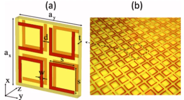
Figure1 shows the schematics of the CMMs we study. The unit cell of the CMM structure consists of double-layered four “U” SRRs共Four-U-SRRs兲 patterned on opposite sides of an FR-4 board. This structure has been mentioned theoretically18 and is discussed in another papers.19,20 The relative dielectric constant of the FR-4 board is 4.0 with a dielectric loss tangent of 0.025. The two layers of Four-U-SRRs are mutually twisted by 90°. The Four-U-Four-U-SRRs are arranged so that the CMM structure possesses C4 symmetry. The dimensions of the unit cell and the photo of our experi-mental sample are shown in Fig.1 and the caption.
In order to study the behavior of the chiral structure, we conducted numerical simulations and experiments. The simulation works were carried out by usingCST MICROWAVE STUDIO 共Computer Simulation Technology GmbH,
Darms-tadt, Germany兲, wherein the finite integration technique was
a兲Electronic mail: [email protected].
FIG. 1. 共Color online兲 共a兲 Schematic of a unit cell of the CMMs consisting of four “U” SRRs.共b兲 A photo of the experimental sample. The geometric parameters are given by ax= ay= 15 mm, t = 1.6 mm, d = 1.5 mm, w
= 0.7 mm, and s = 6 mm. The copper has a thickness of 0.03 mm.
APPLIED PHYSICS LETTERS 97, 081901共2010兲
applied. The periodic boundary conditions were applied to the x and y directions and the absorbing boundary conditions were applied to the z direction. In the experiment, we fabri-cated the chiral structures with a dimension of 20 by 20 unit cells. The transmission coefficient was measured by an HP-8510C network analyzer with two standard horn antennas.
In order to study the transmission behaviors of the chiral structure, in our simulation and experimental works, a lin-early polarized electromagnetic wave共E field in the x direc-tion兲 is incident on the chiral structure. On the other side of the structure, we measured the transmitted field in the x and y polarizations共Txxand Tyx兲. Due to the fourfold rotational
symmetry, circular polarization conversion is absent. The transmission of circularly polarized waves can be converted from the linear transmission coefficients Txx and Tyx,6,7 T⫾
= Txx⫾iTyx. For the transmitted EM wave, the polarization
azimuth rotation angle can be calculated as =关arg共T+兲 − arg共T−兲兴/2. The ellipticity of the transmitted wave is de-fined as= arctan关共兩T+兩−兩T−兩兲/共兩T+兩+兩T−兩兲兴,9
which also mea-sures circular dichroism.
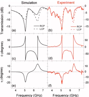
Figures2共a兲and2共b兲show the simulated and measured transmission spectra. There are obvious differences between the transmissions of RCP and LCP waves around the reso-nances. Around the frequency of 5.1 GHz, the transmission of LCP wave is 7 − 8 dB higher than that of the RCP wave. While around the frequency of 6.3 GHz, the transmission of the LCP wave is around 3 − 4 dB lower than that of the RCP wave. The fluctuations on the experiment curve come from the multiple reflections between the CMM structure and the horn antennas.
Figures 2共c兲–2共f兲 show the simulated and experimental results of the polarization azimuth rotation angle and the ellipticity of the transmitted wave. It can be clearly seen that, in the middle of the two resonant frequencies, the
ellip-ticity= 0, where corresponds a pure optical activity effect, i.e., for the linear polarization incident wave, the transmis-sion wave is still the linear polarization but with a rotated angle. The azimuth rotation angleis as large as 26° at 5.5 GHz. The rotation angle per wavelength is 700°/.
Figure3 shows the retrieved effective parameters based on the simulation and experimental data of the transmission and reflection for one layer of the CMMs. In the retrieval process, the effective thickness of the CMM is assumed to be 1.8 mm along the wave propagation direction. The chirality is very large, e.g., it is 2.15 at = 0. If using the following expression20 = − ⍀11 2− 1 2 + i⌫ 11 + ⍀22 2− 2 2 + i⌫ 22 , 共2兲 to fit the result of the chirality , it gives us ⍀1= 0.22,
1= 5.08 GHz,⌫1= 0.02, ⍀2= 0.28, 2= 6.42 GHz, and ⌫2= 0.03. Comparing Figs.3共a兲and3共b兲and Figs.3共c兲and
3共d兲, due to the relation of n⫾= n⫾, the strong chirality can push the refractive index of RCP共LCP兲 wave to be nega-tive around the resonant frequency of 5.1 共6.4兲 GHz as shown in Figs.3共c兲and3共d兲. However, due to the losses in the dielectric board, the figure of merit 关⫺Re共n兲/Im共n兲兴 is only around 1.1 共1.3兲 at 5.1 共6.4兲 GHz in the negative index band. By using a lower loss substrate, the imaginary part of the negative index can be reduced. The figure of merit can be larger than 10 共not shown here兲. In Figs. 3共e兲 and3共f兲, we show the retrieved real parts for the permittivity and perme-ability of the CMM. Obviously, the Re共兲 is always positive throughout the entire frequency range共except the tiny range around 6.4 GHz兲, while Re共兲 is negative in the frequency ranges above the two resonances. In traditional
metamateri-FIG. 2. 共Color online兲 Simulation and experimental results for the CMM. 共a兲 and 共b兲 are the transmission spectra for RCP and LCP waves. 共c兲 and 共d兲 are the polarization azimuth rotation angle.共e兲 and 共f兲 are the ellipticity angleof the transmitted wave.
FIG. 3. 共Color online兲 The retrieved effective parameters of the CMMs based on the simulation共left兲 and experimental 共right兲 data. 共a兲 and 共b兲 show the real parts of the refractive index n and chirality.共c兲 and 共d兲 show the real parts of the refractive indices for RCP and LCP waves.共e兲 and 共f兲 show the real parts of the permittivity and permeability.
als, this will not result in a negative index. Therefore, the negative index of RCP共LCP兲 wave is actually attributed to the relatively small n and large chirality.
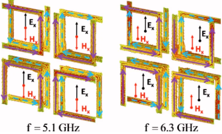
In order to understand the mechanism of the resonances for our Four-U-SRRs CMM, we study the current modes on the Four-U-SRRs. Figure 4 shows the simulated current modes at 5.1 and 6.3 GHz driven by the electric field in the x direction. At 5.1 GHz, the currents on the top and bottom Four-U-SRRs are in the same direction. On the contrary, at 6.3 GHz, the currents on the top and bottom are in the op-posite direction. According to the current distribution, we can analyze the induced magnetic field. Figure4 shows that the x component of the induced magnetic field Hxis nonzero. And moreover, at 5.1 GHz, Hx and Ex are in the opposite directions, while at 6.3 GHz, they are in the same direction. This causality between electric and magnetic fields is consis-tent with the constitute equation Eq. 共1兲.
In summary, by twisting the four “U” SRRs in the propa-gation direction, which owns the fourfold rotational symme-try, a uniaxial CMM can be constructed. We study the struc-ture via the numerical simulation and the experiment at 3.5 − 7.5 GHz. The simulation results agree with the experimen-tal results very well. This artificial structure gives us so strong chirality that the refractive index of RCP or LCP can be pushed to be negative at the vicinity of the resonance.
Such structure can be scaled to other frequencies. The pro-posed chiral structures are suitable for planar fabrication. In the future, we can use this planar design to contracture bulk CMMs via layer-by-layer method.
This work is supported by the European Union under the projects EU-PHOME and EU-ECONAM, and TUBITAK un-der the Project Nos. 107A004 and 107A012. One of the au-thors 共E.O.兲 also acknowledges partial support from the Turkish Academy of Sciences. Rongkuo Zhao acknowledges the China Scholarship Council 共CSC兲 for financial support.
1J. B. Pendry,Science 306, 1353共2004兲.
2S. Tretyakov, I. Nefedov, A. Sihvola, S. Maslovski, and C. Simovski,J. Electromagn. Waves Appl. 17, 695共2003兲.
3A. V. Rogacheva, V. A. Fedotov, A. S. Schwanecke, and N. I. Zheludev, Phys. Rev. Lett. 97, 177401共2006兲.
4B. Wang, J. Zhou, T. Koschny, and C. M. Soukoulis,Appl. Phys. Lett. 94,
151112共2009兲.
5S. Zhang, Y.-S. Park, J. Li, X. Lu, W. Zhang, and X. Zhang,Phys. Rev. Lett. 102, 023901共2009兲.
6E. Plum, J. Zhou, J. Dong, V. A. Fedotov, T. Koschny, C. M. Soukoulis,
and N. I. Zheludev,Phys. Rev. B 79, 035407共2009兲.
7J. Zhou, J. Dong, B. Wang, T. Koschny, M. Kafesaki, and C. M.
Soukou-lis,Phys. Rev. B 79, 121104共R兲 共2009兲.
8M. Decker, M. Ruther, C. E. Kriegler, J. Zhou, C. M. Soukoulis, S.
Lin-den, and M. Wegener,Opt. Lett. 34, 2501共2009兲.
9J. D. Jackson, Classical Electrodynamics, 3rd ed. 共Wiley, New York,
1998兲.
10J. A. Kong, Electromagnetic Wave Theory共EMW, Cambridge, 2008兲. 11C. Enkrich, M. Wegener, S. Linden, S. Burger, L. Zschiedrich, F. Schmidt,
J. F. Zhou, T. Koschny, and C. M. Soukoulis,Phys. Rev. Lett.95, 203901
共2005兲.
12S. Linden, C. Enkrich, M. Wegener, J. Zhou, T. Koschny, and C. M.
Soukoulis,Science 306, 1351共2004兲.
13I. Sersic, M. Frimmer, E. Verhagen, and A. F. Koenderink, Phys. Rev. Lett. 103, 213902共2009兲.
14H. Liu, D. A. Genov, D. M. Wu, Y. M. Liu, Z. W. Liu, C. Sun, S. N. Zhu,
and X. Zhang,Phys. Rev. B 76, 073101共2007兲.
15N. Liu, H. Liu, S. Zhu, and H. Giessen,Nat. Photonics3, 157共2009兲. 16D. H. Kwon, D. H. Werner, A. V. Kildishev, and V. M. Shalaev, Opt.
Express 16, 11822共2008兲.
17C. Menzel, C. Rockstuhl, T. Paul, and F. Lederer,Appl. Phys. Lett. 93,
233106共2008兲.
18N. Liu and H. Giessen,Opt. Express 16, 21233共2008兲.
19X. Xiong, W. H. Sun, Y. J. Bao, M. Wang, R. W. Peng, C. Sun, X. Lu, J.
Shao, Z. F. Li, and N. B. Ming,Phys. Rev. B 81, 075119共2010兲. 20R. Zhao, T. Koschny, E. N. Economou, and C. M. Soukoulis,Phys. Rev. B
81, 235126共2010兲.
FIG. 4. 共Color online兲 The current distributions driven by the electric field in the x direction at 5.1 GHz and 6.3 GHz. The arrows in the middle of the SRRs show the direction of the x component of the induced magnetic field.