Optical and Quantum Electronics
22(1990) 213-226
Effective cut-offs for modes on helical
fibres
A Y H A N A L T I N T A S
Department of Electrical and Electronics Engineering, Bilkent University,
Ankara, Turkey
J O H N D. L O V E
Optical Sciences Centre, Australian National University, Canberra, ACT,
Australia 2601
Received 22 March; revised 24 August; accepted 12 December 1989
Every mode of a single-mode or multimode helical fibre is always leaky but, for practical purposes, can be treated as being bound with an effective cut-off wavelength. The leakage loss for each mode is quantified, showing that, for fixed core offset and source wavelength, the cut-off pitch increases with increasing mode order. The value of the cut-off pitch for each mode is in agreement with experimental measurements.
1. Introduction
There has been significant interest in single-mode helical fibres, mainly because of their high circular birefringence property. This can be used, for example, as the basis for the measure- ment of electric current flow by measuring the rotation of the polarization of the funda- mental mode caused by the Faraday effect. A large circular birefringence is necessary to eliminate any cross-coupling between the orthogonal polarizations of the fundamental mode due to non-uniformities in the practical fibre. It is akin to high-birefringence fibres which have a large linear birefringence for the same reason.
I f the core of a single-mode fibre follows a helical path, then the polarization of the fundamental mode rotates along the path [1]. This phenomenon arises because the direction of the modal electric field in the core cross-section is unaffected by the rotation of the local plane of curvature (that is, the plane defined by the tangent and normal to the core axis of the helix) and therefore lags behind the twisting of the core material. The magnitude of the lag is precisely the mathematical torsion of the helix, for which a simple expression is well known [1].
However, unlike a straight single-mode fibre, the fundamental mode of the helical fibre is not strictly bound, and is leaky at all wavelengths [2]. For practical purposes, however, the loss is effectively negligible if the helix is 'straight enough' and the mode can be considered to be bound. If the helix becomes sufficiently 'wiggly', then the loss increases very rapidly, as in a bend loss edge, and there is an effective cut-off that depends on the geometrical parameters of the helix.
An analytical expression for the fundamental-mode loss coefficient has been quoted elsewhere [2], the details for which are presented for the first time in the Appendix.
Ayhan Altintas, John D. Love The derivation is based on the thin-wire approximation in which the modal field over the core cross-section is superposed on to the core axis before evaluating the far-field radiation. However, as i s shown below, the thin-wire approximation is inaccurate for calculating the loss coefficient for higher-order modes on multimode helical fibres, and the field variation over the finite core cross-section must be accounted for correctly. One conse- quence of this requirement is the inability to generate an analytical expression for loss which spans the range of helical parameters. Nevertheless, by restricting attention to parameter values t h a t result in pure bend loss, analytical expressions can be derived which are sufficient to explain the observed experimental results on the multimode fibre. This deri- vation complements an earlier, alternative derivation based on field matching between the helical core and the cladding [3].
2. Helical f i b r e s
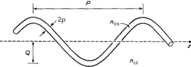
A helical fibre consists of a core of radius p which follows the spiral path illustrated in Fig. 1. The path of the core axis is at a constant radius Q, called the offset, from the z-axis of the helix and the pitch, or period, of the helix, P, is the distance along the z-axis in which the helix repeats itself. We assume a step profile with a core of index nco embedded in an unbounded cladding of index ncl.
In practical helical fibres Q is typically of the order of hundreds of micrometres and P is of the order of millimetres. The fibre can be either single-moded or multimoded, depend- ing on the number of nominally bound modes which can propagate. Unlike the correspond- ing straight fibre, the number of modes does not depend solely on the V-value of the fibre, but is also a function of the pitch and offset. As is shown below, a nominally multimode helical fibre with V >> 1 can be single-moded, or even support no modes, provided the pitch is sufficiently small.
In one method for fabricating helical fibres, a standard single- or multimode preform is inserted into a predrilled hole in a solid silica rod which is offset from the axis o f the rod [4]. During the drawing process the rod is spun about its axis to introduce the helicity into the fibre. By controlling the spinning rate, any desired pitch can be achieved, but the offset remains fixed.
3. R a d i a t i o n loss
As has already been established, the fundamental mode of a dielectric helical waveguide is necessarily leaky [2]. The leakage is due to a combination of two physical processes: pure bending loss from the continuously curved path of the core, and interference between the fields of successive turns of the helix (analogous to the effect of a grating impressed on a straight fibre). The former dominates when the radiation caustic (that is, the apparent
I
~ P =1Effective c u t - @ for modes on helical fibres
origin of radiation) is relatively close to the core-cladding interface and only the local modal field contributes to bend loss, and the latter dominates when the radiation caustic is relatively far from the core-cladding interface and the modal field of the macroscopic helical structure accounts for loss.
The magnitude of each effect depends on the pitch and offset of the helix. For practical fibres loss is negligible unless the bend radius in the plane of the helical path is sufficiently small or the pitch is sufficiently small to induce significant diffraction loss. Nevertheless, the onset of loss is extremely rapid, like a bending edge, in each case and can be regarded as an effective cut-off [2].
4. H i g h e r - o r d e r m o d e s
Quantification of radiation loss due to bending loss for the higher-order helical modes follows the volume-current approach used for the fundamental mode [2]; except that the finite core must be accounted for. The modal field over the core of the helix is assumed to be the field of the straight fibre following the helical path. Both the core and field are then approximated by a helical distribution of equivalent currents. The radiation is quantified from these currents using standard free-space antenna theory (Green's functions) to deter- mine the far field of the helix [5].
4.1. L o c a l - m o d e a p p r o x i m a t i o n
The core and cladding refractive indices of the helical fibre in Fig. 1 are similar, enabling us to work within the weak-guidance approximation. Even so, it is not possible to solve the scalar wave equation analytically in any known helical co-ordinate system. Instead, we start with the local-mode approximation for the helix. Within this approximation, a mode propagates along the helical path of the core with the transverse field and propagation constant of the straight fibre.
Such an assumption will be accurate, provided the cladding field transverse to the helical core axis does not intersect the core again further along the helix. If the ratio of pitch to offset is sufficiently large, the helix is almost a straight fibre and there is clearly no intersection. However, if this ratio is sufficiently small, so that the helix resembles a 'solenoid', then there will be a large number of intersections. Thus, there is a critical value of this ratio below which intersection occurs. If we ignore the finite core size compared with the pitch and offset, then simple geometry requires that P ~> 4.173Q to avoid intersection. For the practical fibres discussed below, Q is of the order of hundreds of micrometres and P is of the order of millimetres, so that this condition is readily satisfied, even at the cut-off pitch of each mode.
The local-mode analysis for the fundamental mode of a helically wound straight fibre is given in the Appendix, where the uniform distribution of the core field is lumped on the fibre axis. The result obtained yields both helical and bending loss limits for different combi- nations of pitch and offset [2]. The non-zero thickness of the fibre can be included through an area factor, as described in [5], but only for the helical bending loss regime of the fundamental and higher-order HElm modes.
4.2. Area factor
The determination of the loss coefficient for higher-order modes of the helical fibre, even based on bending loss alone, is more involved than for the fundamental mode because of the need to take into account the finite cross-section of the core. For the relatively low
A y h a n Altintas, John D. L o v e V-values of the single-mode fibre, the effect of retaining the finite core cross-section compared with superposing the modal field on the fibre axis is to increase the loss coefficient for the fundamental mode by a factor of about 2 (see section 23-8 of [5]) whereas for a multimode fibre with V = 25 the corresponding factor is of the order of 10 6.
Some insight into the dramatic increase in loss from the same mode on the high-V fibre can be gleaned by examining the position of the radiation caustic relative to the core- cladding interface.
4.3. Radiation caustic
It is intuitive that the magnitude of the radiation loss from a bent fibre depends on the separation of the radiation caustic (apparent origin of radiation) from the core- cladding interface, with radiation increasing with decreasing separation. Furthermore, since the major contribution to radiation from a bent fibre comes from a small region close to the plane of the bend [5], it is sufficient to calculate this separation in the plane of the bend.
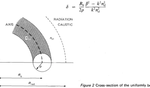
The bend radius of the fibre axis in Fig. 2 is R b and fl is the fundamental-mode propagation constant along the core axis. Hence, the phase velocity of the modal field front along the fibre axis is ~/fi, where c~ is the angular frequency of the source and ~o = 2~c/2 in terms of the free-space wavelength 2 and speed of light c. Relative to the centre of the bend, C, the angular velocity of the field front is ~o/fiRb. On the radiation caustic the local phase velocity is equal to the speed of light in the cladding, co/knol. Hence, if the radius of the radiation caustic is Rrad, then
Rra d = (fl/knr b (l)
The separation of the radiation caustic from the core-cladding interface is R.. d - R b. If we define 5 to be the normalized separation relative to the core radius, then
6 = (R,ad - - R b ) / p
(2)
If we substitute for Rra d from Equation l, multiply the numerator and denominator by fl + k n d and set fi .~ knd in the denominator, since the fibre is weakly guiding, .then
Rb f12 - - k F/cl 2 2 5 = 2p 2 2 (3) k G1 R A D I A T I O N AXII CAUSTIC 4 R b Rrad
Effective cut-offs for modes on helical fibres
We express the propagation constant fl in terms of the cladding modal parameter W, and the core radius p in terms o f the fibre.parameter V, where
m = p ( f l z - - ,~, ,,cl)/Z2~2 ]1/2 V =
kpnco(2A) 1/2
(4) and A is the relative index difference. Since nco ~ ncl for weakly guiding fibres,W 2
6 = (2A)3/2kn~iRb
2V 3 (5)Thus, if the single- and multimode fibres have the same relative index difference and bend radius, 5 depends only on the factor
W2/V 3.
F o r a single-mode, step-profile fibre with V = 2.4, the eigenvalue equation gives W = 1.748 for the fundamental mode [5], whence
W2/V
3 = 0.22, whereas for the multimode fibre with V = 25, then W ~ 25 andW2/V 3
= 0.04. Hence, 6 is an order of magnitude smaller for the multimode fibre, and the radiation loss from the fundamental mode will be correspondingly larger because the radiation caustic is very much closer to the core- cladding interface.4.4. Polarization effects
It has been shown that the direction o f the transverse electric field o f the fundamental mode on a helical fibre rotates along the core at a rate equal and opposite to the mathematical torsion of the helix [1]. This result has been established experimentally using a large loop of fibre [1] and helical fibres of various pitches [6]. Physically, the polarization direction is unaffected by the helical twisting of the fibre, because of the circular symmetry of the cross-section. Consequently, the same conclusion must hold for all higher-order modes of the helix.
The rotation length Lr for the modal field (that is, the distance along the helix in which the field rotates by 2~) is given by [6]
SP
Lr - S - P (6)
where P is the pitch and S is the fibre length per pitch, given in terms o f the offset Q by
S = [p2 + (2~cQ)2],/2 (6a)
Since P >> Q for the fibres considered in this paper,
L ~
P3/2~2Q2
(7) For the parameters of the helical fibre considered in Fig. 3, P ~> 5 mm and Q = 200/~m, equivalent to a minimum rotation length of 15 cm. Thus, the helix makes many turns in this length, so that the effect of polarization rotation on the far field, and hence loss, is minimal. Accordingly, the assumption of a fixed polarization direction is a reasonable approximation. We can further justify this assumption in the limit of pure bend loss, because such loss depends only on the local geometry and, to lowest order in the relative index difference between the core and the cladding, is independent o f polarization.4.5. Analysis of bend loss
To determine the area factor for higher-order modes, an analysis similar to that in section 23-7 of [5] will be followed. With reference to fig. 23-2(a) o f [5], the Z-component of the
A yhan Altintas, John D. Love
10 60t tl
lO2
I1
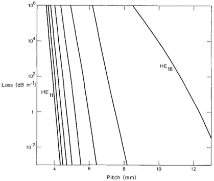
10-2 I I l I 4 8 10 12 Pitch (mm)Figure 3 Attentuation of the H Elm modes of a multimode helical fibre as a functon of the pitch for fixed offset.
electric field is taken to be
(Jv(UR)
core
E z = eim cos (vtp)
JKv(WR)
(8)I ~ cladding
where R =
r/p, v
is the azimuthal m o d e index, r and 0 are polar co-ordinates in the core cross-secton, J~ is the Bessel function o f the first kind and K~ is the modified Bessel function of the second kind. The parameters U and W are roots o f the following eigenvalue equation for the mth mode in each category:UJv+'(U) = W Kv+'(W)
(9a)L(u)
K~(W)
V 2 = U 2 + W 2 (9b)
The equivalent current density then can be written as
j = 2 i k ( % ~ 1/2
Jv(UR)
-- (n2~ - n2o) cos (v0)e i#: (10)
#o /
where z = (Re + r cos 0) q~ for the bent fibre of fig. 23-2(b) in [5].
Due to the sinusoidal variation o f the field around the fibre axis, it is not possible to lump the field o f the fibre on the axis, as was carried out for the fundamental mode, because the net equivalent current would be zero. However, one can include the effect of finite thickness of the fibre core through an area factor which, in the case of the fundamental mode,
Effective cut-offs for modes on helical fibres
multiplies the result derived by lumping the field on the axis. For the sake of brevity, only the slight changes to the steps in [5] are presented.
In the radiation integral, the phase factors coupled with the azimuthal variation of the core field results in a factor of/~ (WR) instead of
I o (WR)
for the fundamental mode which has no azimuthal variation (see equations 23-20 and 37-65 of [5]). Considering this, the area factor is written asfo Fv(R)Iv(WR)R dR
Io Fv(R)2R dR
x 2~ f~ ~ (11)
A =
Io F~(R)R dR
f :
Fv(R) 2 cos 2(vO)R dR d o
where Fv (r) is the radial part of the local mode in Equation 6. This area factor then yields the power attenuation coefficient as
7 -
p \ R b J
evVZWB/2K~ ,(W)Kv+,(W)
exp 3 (kno~) 3 -~ (12) where ev = 2 if v = 0 and ev = 1 otherwise. This result is identical to Equation 28 of [7] for the bending loss of higher-order modes, provided it is further assumed that/3 ~knd
within the weak-guidance approximation. 4.6. Helical bend loss
The bending loss of the helical fibre is obtained directly from the result for a bent fibre, provided the bend radius R b is replaced by the radius of curvature in the plane of the tangent
and normal to the core axis, namely Q/sin 2 0p [2, 3], where 0p is the pitch angle, and 0p ~ sin 0p ~ tan 0 v ~
2~Q/P
(13) for the small values found in practical fibres. Thus1 p2
(14)
R b - 4~2 Q
which is substituted into Equation 12. 4.7. Effective c u t - o f f
An effective cut-off for modes of a bent fibre has been previously proposed [8]. It requires the radiation caustic in the plane of curvature to coincide with the core-cladding interface. This is equivalent to setting 5 = 1 in Equation 5. On rearranging and setting
V ,,~ kpnc~(2A) m,
p V 2
Rb -- A W 2 (15)
For the helical modes we substitute for RB from Equation 14, and on rearranging obtain the pitch length below which the mode is effectively cut off by bend loss:
P = 2 ~ V ( P Q y / 2
W \ A (16)
A similar expression for cut-off has been derived using ray arguments [9]
Ayhan Altintas, John D. Love Accordingly, one would expect this expression to be accurate for large values of V. In this limit both Equations 16 and 17 are independent o f U, V a n d W, since W ~ V a n d U ~ V for the step profile. However, they still differ by a factor of (Q/2p) ~/2. The reason for this difference is that the two expressions are mutually exclusive. Equation 16 is a localized expression, based solely on bend loss, whereas Equation 17 is a global expression based on the whole helical structure. In the absence of an expression' analogous to Equation 12 for helical loss for higher-order modes, it is not possible to make a meaningful comparison using Equation 17.
5. Results
The radiation loss was Calculated as a function o f pitch length using the above technique for the helical multimode step-profile fibre used in the Southampton experiment [9], with parameters V = 25, relative index difference 0.94%, core radius p = 12.5/tm and a fixed offset Q = 200/tin. This fibre was illuminated using a laser source, which means that, essentially, only the symmetric HElm modes of the helix were excited. For V = 25, only the first eight HElm modes o f the corresponding straight fibre are bound.
The loss o f each HElm mode is plotted in dB m ~ as a function o f pitch in millimetres in Fig. 3 for m = 1, 2, . . . , 8. We note that the loss curves are approximately straight, except for the highest-order mode, and the separation between adjacent curves increases with order. In other words, the effective Cut-off pitch is much sharper for the lower-order modes.
I t is interesting to evaluate the effective cut-off pitch for each mode as predicted by Equation 16. For the parameter values given above, we find that P ranges from 3.25 mm for the HE11 mode up to 8.62mm for the HEIs mode. Thus, all of the eight P-values are underestimates for Fig. 3, especially for the lower-order modes.
6. Comparison w i t h experiment
A multimode helical fibre with a nominally step-profile and parameter values given in Section 5 was fabricated at Southampton University, England. During the drawing of the preform, the rotational speed was slowly reduced to increase the pitch length.
When this fibre was illuminated with a laser source at a wavelength of 630 nm from the end with the largest pitch, discrete bands of radiated light were observed along the length of the fibre and were attributed to the cut-offs discussed above. It was not possible to measure the position of each band with high accuracy. The parameters for the Southampton multimode helical fibre are such that radiation loss is dominated by bending loss.
The spacing between successive bands was found to be comparable with the theoretical predictions. Even though it was difficult to identify the modes corresponding to different bands, the experimental results are in keeping with the loss edges. Note the closeness o f these values for the first two H E modes, reflecting the experimental accuracy necessary to realize single-mode operation. For a sufficiently short pitch, below about 2 mm, even the fundamental mode is effectively cut off.
A p p e n d i x : F u n d a m e n t a l - m o d e loss on a helical f i b r e
The calculation o f the radiation from the set of HElm modes of the multimode helix is tractable within the volume-current method, provided the distribution o f equivalent cur- rents across the core is superposed on the fibre axis. However, as was shown in Section 4.2, the final expression becomes increasingly inaccurate with increasing mode order m and is,
Effective eut-offs for modes on helical fibres
therefore, most accurate for the fundamental mode. In this Appendix we show how the final loss expression is derived, including approximations made en route.
A1. Equivalent helical c u r r e n t
We assume that the field of the HE1,, mode following the helical path of the core is a local mode; that is, it has the scalar field and propagation constant of the corresponding m o d e of the straight fibre. Assuming the field is plane polarized parallel to the x-axis in Fig. A1, then the core field is given by
Ex - Jo (UR) ei~S (A 1)
go(U)
where S is the distance along the helical core axis, and other quantities have been defined in the text. Within the volume-current method, the field and core are replaced by an equivalent distribution of currents Jx occupying the core volume in a uniform medium of refractive index no1, where [5]
( a0 ~1/2 k(nZl _ n2o)Ex 0 ~< R ~< 1 (A2) Jx = i \ ~ 0 /
The next step is to replace this distribution by a superposition on the core axis, that is by an integration over the core cross-section. Thus
J~ = #e i~s (A3a)
( eo ~,/2 k(n~l - n~o) (a3b)
~c = f~ f2 ~ Jo(UR) 2zcp 2 J,(U) (A3c) Jo(U---~ r d o dr - U Jo(U)
As has been shown for pure bending loss in single-mode fibres [5], the superposition approximation leads to an error in the power attentuation coefficient of order 1, which can be neglected compared with the exponential dependence on the bend radius. Without this approximation the analysis becomes intractable.
We now refer the spatial dependence in Equation A3a to the distance z' along the axis of the helical structure in Fig. A1, which is related to the distance along the core
. . . . - - T
-- -- -- - - - - - - ~ -
. . . .
p
2L
Ayhan Altintas, John D. Love
axis by
z' = S c o s 0p (A4)
where 0p is the pitch angle between the tangent to the core axis and the z'-axis in Fig. A1. In terms of the parameters of the helix
0p ,~ tan Op =
27zQ/P
(A5)since 0p ~ 1 for practical fibres.
Relative to the polar co-ordinates (r', 05', z') in Fig. A1, the spatial path of the super- posed current is defined by
r' = Q
05' = 2rcz'/P
(A6)assuming 05' = 0 at z' = 0. Hence Equation A3a is replaced by
6(r' - Q) (
~ ) e,~Z,/~osOp
J~ = # C9 6 0 5 ' - 2re (A7)
A2. R a d i a t e d p o w e r
The power radiated from the helix is calculated from the vector potential in the far field. In terms of the notation in Chapter 21 of [5], this vector has only an x-component, whence
)r
M~ = # ~ 6 05' - 2 ~ e x p i
kds'cosz
dr'd05'
cos 0pwhere the integration is over the volume occupied by Jx, k~l =
knc~
ands ' c o s ~ = s' sin 0' sin 0 cos (05 - 05') + s' cos 0' cos 0 (ASb) = r' sin 0 cos (05 - 05') + z' cos 0 (A8c) If we consider a length 2L of the helix bounded by z' = _+ L, then Equation A8a reduces to Mx = / ~ f C L e X p i [
Z'[3
kdz'cosO~,QsinOcos(05-2g~)]dz'
(19)cos 0p
The trigonometric dependence on z' in the exponent is expanded as a series using the relationship [5]
exp ( - i z cos 0) =
Jo(z) + 2 ~
(-i)mJm(Z)
COS(mO)
(A10)m - I
leading to
M x = where for m ~> 0
Fro=
It (Jo(kc~Q
sin 0)F0 + 2 m = I ~(-i)mJm(k~ sinmO)Fm)
( A l i a )L c o s m 05 -- 2re e x p i cOS0p
sin
L[(fl/cos
0p) -- kd cos 0 +2mn/P]
elm+(fl/cos 0p) - kcl cos 0 +
2mTz/e
sin
L[(fl/COS
0p) -- kcl cos 0 --2mg/P]
e_im ++ (Allc)
Effective eut-offs for modes on helical fibres
T h e r e are two simple limits t h a t we can e x a m i n e as a check o n the analysis at this stage. I f the offset Q ~ 0, only the m = 0 t e r m remains and
Mx = 2#6(/~ - kd cos 0) (A12a)
since cos 0p ~ 1, c o r r e s p o n d i n g to the result for a straight fibre. Similarly, if the pitch P ~ ~ , then cos 0p ~ 1 and
M x ~ 2rc#6(/~ - kcl cos 0) exp
(ikdQ
sin 0) (A12b) which is the result for a straight fibre displaced radially a distance Q f r o m the z'-axis.G i v e n Mx, the total r a d i a t e d power, Praa, follows f r o m [5] as
Prad = O" dq~ ~o dO sin 0 (1 - sin 2 0 sin 2 4~)lMx] 2 (A13a)
where
k2n~176
(A13b)a - 3 2 n 2 \ ~ 0 /
It follows f r o m E q u a t i o n A11 t h a t M~ comprises a d o u b l y infinite set o f terms, leading to a very c o m p l i c a t e d expression for Prad" H o w e v e r , a significant simplification follows f r o m a n e x a m i n a t i o n o f the v a r i a t i o n o f
Mx
with 0, bearing in m i n d t h a t we are interested in the limit L ~ ~ . I f we recall t h a t the m a x i m u m value o f the function (sinx)/x
occurs at x = 0, then in this limit, Mx is essentially zero everywhere except in the vicinity o f a set o f discrete values 0 =Om
for whichfl S
2mn
cos 0m - (A14)
kol P
Pkd
since cos 0p =
P/S.
T h e r e is only a discrete range o f values o f m, the m i n i m u m value mmin, being the solution closest to cosOm
= 1, a n d the m a x i m u m value, m . . . . being the solution closest t o cosOm= -- 1.
Thus, Mm comprises mma x - - mmi n + 1 spikes, and, therefore, M 2 has the s a m e distri-
b u t i o n o f p e a k s and is a p p r o x i m a t e d well b y
sin 2 L[(/l/cos 0p) -- kd cos 0 --
.2mn/p]
]Mx] 2 = 4#2L 2 ~J2m(kol Q
sinOre)
-~[(~-~-~-p-~ ~_ ~clSO-~ ~_ 5m~---~ (A15) which is i n d e p e n d e n t o f ~b. H e n c e the ~b-integration in E q u a t i o n A 13a is readily p e r f o r m e d , a n d the total r a d i a t e d p o w e r reduces to4za# 2
Prad -- - kc 1 -
L ~ JZ(kdQ
m sinOm)
(1 + cos z 0m) f:+ sin2 z z - ~ dz ( A I 6 ~ ) .- where mmi n ~< m ~< mma x a n dz = L[(/~/cos 0p) -- kd cos 0 --
2mTz/P]
(A16~0) T h e z + and z - c o r r e s p o n d to the value o f z w h e n m = m ~ , and m = m . . . . respectively. I f we n o w increase L indefinitely, the integral in E q u a t i o n A 1 6 a has value re, whence4~ 2 a # 2
Ayhan Altintas, John D. Love where 0 m is defined in Equation A14. Hence, the total radiated power consists of a
summation of powers associated with peaks, or lobes, in the far field. A similar result has been derived using radiation modes and is plotted, for example, in fig. 9 of [10].
A3. Power attenuation coefficient
The radiated power attenuates each
HElm
mode. If we introduce a power attenuation coefficient y, then the power P(z) at a distance z along the axis of the helical waveguide is related to the initial power byP(z) = P(0) exp ( - 7z) (A18)
and the power attenuation coefficient is given by
1
Prad
? - (A19)
2L P(0)
The initial power, P(0), is given in [5], so on substituting from Equation A17 we finally obtain
7 - ~ (1 + cos 20m)J2m(kdQ sin 0m) (120)
We now take advantage of the very large number of peaks in the far field to replace the summation in Equation A20 by an integral. The unit incremental change in m in Equation A14 corresponds to a change d0,. in 0m, whence
sin 0 m d O m = 2rc/kclP (A21)
and Equation A20 is replaced by
1 P
f2 (1 + cos 20m)JZm(kcjQ sin Ore) sin 0,. dora (A22) Y - 4 p p -
-A4. Approximate expression for loss
This integral is not tractable, but we can generate a good approximation to it by observing that the major contributon to the integral comes from the range of 0m-values in the region where the argument and order of the Bessel function are approximately equal, that is where m ~ kcj Q sin Ore. The Bessel function can be approximated in terms of the Airy function of the first kind by [11]
Jm(Z) -- m -q73 Ai --m (m -- z) (123)
whence Equation A22 is replaced by
4p
1 (--~---~)
2P
p (2) 2/3
Y = fo sin Ore(1 + cos 2 0m) Ai 2
[(Z
(m - Q k d sin 0m) d0 m]
(A24) where for small ;values of 0" and 0p, we find with the aid of Equation A14 thatm - Qkd sin 0m ~ ~ A 1 + (A25a)
Effective cut-offs for modes on helical fibres
It is now clear that the major contribution to the integral comes from the region close to
Om
= 0p. Hence we setOm
= 0p everywhere except in Equation A25a, then since 0p ~ 1,OpP(2)2/3(-~--)2foAi2[(2)l/3(m-QkclsinOm)]dO
m
(A26)= 2 - 7 7 where
-- Skclz~(~-)2[l-F
(----~)2~
-]
(A27)
rh 2re
The argument of the Airy function is large and negative, whence it can be approximated by the asymptotic form [11]
1 1 ( 2 )
Ai(z) ,.~
2rd/2 z1/4
exp- -j z 3/2
(A28)On substituting the appropriate expressions from Equations A25, A27 and A28, the integral in Equation A26 becomes
1 - 1 4
-~n(2)'/6-~exp[--~(2)l/20~3/2]I
(A29a)
where andI = f o e X p [ - 2(2)l/2c~3/2(--~)z(OP2?m)2]dO m
(A29b)Skd
A (A29c) = 2reWe evaluate the integral in Equation A29b using a change of variable to 0p -
Om
and integration over --oo < 0 < oo:I = 0~3/4 (2A) 1/2 (A30)
Finally, putting Equations A26, A27, A29 and A30 together,
(~)l/2Tc2QV5/2
1
( 2 A 1 / 2 S W 2
1
)
7 = A,/4p3/2
U 2
(1 + e) ~/4exp 3 ~ p V (1 + e)l/2 (A31a) where(0p
e = 2 \0o W]
(A31b)in terms of the pitch angle of Equation A5 and the complementary critical angle 0c (2A) 1/2, assumed small.
A5. Asymptotic form
By analogy with the derivation of 5 in Equation 5, it is straightforward to show that g is the ratio of offset Q to the distance from the core-cladding interface to the radiation caustic,
Ayhan Altintas, John D. Love
R,~a
- (Rb + p). Accordingly, if e ~ 1, the radiation caustic is close to the interface and 7 reduces to the expression for pure bending loss in the thin-wire approximations, for example equation 23-13 of [5].A c k n o w l e d g e m e n t s
We thank Dr A. Ankiewicz and Dr R. D. Birch for helpful discussions.
References
1. J.N. ROSS, Opt. Quantum Electron. 16 (1984) 455.
2. J.D. LOVE and A. W. SNYDER, Electron Lett. 23 (1987) 1109. 3. D. MARCUSE, J. Opt. Soc. Am. 66 (1976) 1025.
4. R . D . BIRCH, Electron Lett. 23 (1987) 50.
5. A.W. SNYDER and J. D. LOVE, 'Optical Waveguide Theory' ( C h a p m a n and Hall, London, 1983). 6. P. VARNHAM, R. D. BIRCH and D. N. PAYNE, in Proceedings o f I O O C - E C O C International Conference on
Integrated Optics of Optical Fibre C o m m u n i c a t i o n - European conference on optical communication, Venice, Italy (1985) 135.
7. D. MARCUSE, J. Opt. Soc. Am. 66 (1976) 216.
8. Idem, ibid. 66 (1976) 311.
9. M.P. VARNHAM, R. D. BIRCH, D. N. PAYNE and J. D. LOVE, in Proceedings of Conference on Optical Fiber C o m m u n i c a t i o n . Atlanta, Georgia, U S A (1986) p. 68.
10. M.T. WLODARCZYK a n d S. R. SESHADRI, J. Lightwave Teehnol. LT-3 (1985) 713.
11. M. ABRAMOWITZ and I. A. STEGUN (editors), ' H a n d b o o k of Mathematical Tables' (Dover, New York, 1965).