Dergi web sayfası:
www.agri.ankara.edu.tr/dergi www.agri.ankara.edu.tr/journalJournal homepage:
TARIM BİLİMLERİ DERGİSİ
—
JOURNAL OF AGRICUL
TURAL SCIENCES
21 (2015) 558-571
The Effects of Strainer Types on Flow Characteristics of Anti-Drift
(AD) and Multi-range (LU) Flat-Fan Nozzles
Bahadır SAYINCIa, Mazhar KARAa
aAtatürk University, Faculty of Agriculture, Department of Agricultural Machinery and Technologies Engineering, 25240, Erzurum, TURKEY ARTICLE INFO
Research Article
Corresponding Author: Bahadır SAYINCI, E-mail: [email protected], Tel: +90 (442) 231 26 92 Received: 13 August 2014, Received in Revised Form: 24 October 2014, Accepted: 29 October 2014
ABSTRACT
This study investigated the effects of four different strainer types on flow characteristics (orifice coefficient (k), exponent
coefficient (n), individual flow rate deviation (φ) and discharge coefficient (Cd)) of different nozzle types. The volumetric
flow rates of anti-drift (AD) and multi-range (LU) flat-fan nozzles of three different orifice sizes were determined at different operational pressures (1.5, 3.0, 4.0, 6.0 and 8.0 bars). In each treatment, the nozzles were used together with cup screen strainer of 50-mesh, slotted strainer, cylindrical strainers of 40-, 50-, and 80-meshes, and ball-check strainers of 50- and 80-meshes. The flow rate measurements were also obtained without strainers. The relation between the flow rate (Q) and spray pressure (P) for each nozzle combination (nozzle type, strainer type, and orifice size) was presented using the power regression model . The “k” coefficient, which is the slope of the line referring to the relation between the nozzle flow rate and spray pressure, was evaluated as a comparison parameter between the nozzle combinations. The “k” mean values of the nozzle types using with ball-check strainers were lower than those of the without strainer, cup screen, slotted and cylindrical strainers. This result showed that the volumetric flow rate decreased with respect to the other nozzle combinations operated at the same operational pressure. Thus, the deviation rate from the nominal flow rate of the nozzles used with the ball-check strainers exceeded the acceptable deviation limit of ±10%. As the “n” coefficients of the LU and AD nozzles used with cup screen, slotted, cylindrical strainers and without strainers were close to 0.50, the ball-check strainers resulted in increasing the “n” coefficient of the nozzles. The “n” coefficient of the nozzles used with the ball-check strainers of 50- and 80- meshes was determined as 0.586 and 0.608 for the AD nozzle, respectively and, 0.576 and 0.584 for the LU nozzle, respectively. The ball-check strainers dramatically decreased the discharge
coefficient (Cd) of the nozzles compared to the other strainers and the usage without strainer. For the cup screen, slotted,
cylindrical strainers and the usage without strainer, the Cd means ranged from 0.67 to 0.77 for the AD nozzle, and 0.91
to 0.94 for the LU nozzle. The Cd means of the nozzles used with the ball-check strainers of 50- and 80- meshes were
determined as 0.39 and 0.34 for the AD nozzle, respectively, and 0.56 and 0.53 for the LU nozzle, respectively. Keywords: Antidrift nozzle; Flat-fan nozzle; Discharge coefficient; Flow rate; Multi range nozzle; Strainer
Süzgeç Tipinin Düşük Sürüklenme Potansiyelli (AD) ve Yüksek Etki
Alanlı (LU) Yelpaze Hüzmeli Memelerin Akış Karakteristiklerine Etkisi
ESER BİLGİSİ Araştırma Makalesi
Sorumlu Yazar: Bahadır SAYINCI, E-posta: [email protected], Tel: +90 (442) 231 26 92 Geliş Tarihi: 13 Ağustos 2014, Düzeltmelerin Gelişi: 24 Ekim 2014, Kabul: 29 Ekim 2014
559
Ta r ı m B i l i m l e r i D e r g i s i – J o u r n a l o f A g r i c u l t u r a l S c i e n c e s 21 (2015) 558-571
1. Introduction
Flat-fan nozzles have been widely used for broadcast spraying of the crop protection products (Zhou et al 1996). Multi-range spray nozzles are similar to the standard flat-fan nozzles in terms of the design features and produce droplets prone to drift at low operational pressure (up to 2.5 bars) (Lechler 2013).
There is a tendency towards to usage of new generation nozzles because of the droplets prone to drift, and because the deposition efficiency of coarse droplet produced by these nozzles is higher than the fine droplets which are produced by standard flat-fan nozzles.
Anti-drift nozzles as new generation nozzles have a pre-chamber in nozzle body which reduces the proportion of droplets which were prone to drift (Wilkinson et al 1999). The pre-chamber into the nozzle body disperses the pressure before the liquid discharges and produces medium and coarse droplets
with low drift potential. The anti-drift nozzles have been preferred operating at low pressure of 3.0 bars (Knewitz et al 2002).
One of the most important distinctive features of the anti-drift nozzles compared to the standard flat-fan nozzles is that the orifice area of it is bigger than that of the standard nozzles. Also, the circular diameter of the pre-orifice is larger than the equivalent diameter of the nozzle’s exit orifice which is V-shaped. Although the orifice sizes of the standard and anti-drift nozzles are different, they can be produced at identical nominal flow capacity. This feature relating to the nozzle geometry is an important design parameter based on the flow dynamic.
Agricultural spray nozzles are manufactured in accordance with the standardized colors and nominal sizes, which were indicated by institutions (ISO Standards 2005; ASABE Standards 2009). The nominal sizes defined for each color of the nozzle
ÖZET
Bu çalışmada dört farklı süzgeç tipinin değişik meme tiplerinin akış karakteristikleri (orifis katsayısı (k), üs kuvvet
katsayısı (n), bireysel debi sapma oranı (φ) ve akış katsayısı (Cd)) üzerindeki etkileri araştırılmıştır. Üç farklı orifis
ölçüsüne sahip düşük sürüklenme potansiyelli (AD) ve yüksek etki alanlı (LU) yelpaze hüzmeli memelerin farklı işletme basınçlarında (1.5, 3.0, 4.0, 6.0 ve 8.0 bar) hacimsel debileri belirlenmiştir. Her bir denemede memeler yuvarlak süzgeç, yarıklı süzgeç, 40-, 50- ve 80-mesh’lik silindirik süzgeçler ile 50- ve 80-mesh’lik çek-valfli silindirik süzgeçlerle birlikte kullanılmıştır. Debi ölçümleri süzgeç kullanılmadan da yapılmıştır. Her bir meme kombinasyonu için (meme tipi, süzgeç tipi ve orifis ölçüsü) debi (Q) ve püskürtme basıncı (P) arasındaki ilişki üssel regresyon eşitliği kullanılarak verilmiştir. Meme debisi ve püskürtme basıncı arasındaki ilişkiye ait doğrunun eğimi olan “k” katsayısı meme kombinasyonları arasında bir karşılaştırma parametresi olarak değerlendirilmiştir. Çek-valfli silindirik süzgeçle kullanılan meme tiplerinin “k” ortalama değeri süzgeçsiz, yuvarlak, yarıklı ve silindirik süzgeçlerin kullanımlarından daha düşük bulunmuştur. Bu sonuç, hacimsel debinin aynı işletme basıncında işletilen diğer meme kombinasyonlarına göre azaldığını göstermektedir. Bununla birlikte, çek-valfli süzgeçlerle kullanılan memelerin nominal debideki sapma oranı ±% 10’luk limiti aşmıştır. Yuvarlak süzgeç, yarıklı süzgeç, silindirik süzgeç ve süzgeçsiz kullanılan LU ve AD tip memelerin “n” katsayısı 0.50’ye yakın iken, çek-valfli silindirik süzgeçler, her iki meme tipinin “n” katsayısının artmasına neden olmuştur. 50- ve 80-mesh’lik çek-valfli silindirik süzgeçlerle kullanılan AD tip memelerin “n” katsayısı sırasıyla 0.586 ve 0.608 olarak bulunmuştur. LU tip memelerde ise “n” katsayısı 50- ve 80- mesh’lik çek-valfli silindirik süzgeçler için sırasıyla 0.576 ve 0.584 olarak belirlenmiştir. Diğer süzgeçlerle ve süzgeçsiz kullanımla karşılaştırıldığında çek-valfli olanlar
memelerin ortalama akış katsayısını (Cd) azaltmıştır. Yuvarlak, yarıklı ve silindirik süzgeçlerle ve süzgeçsiz kullanımda
AD memenin Cd ortalaması 0.67-0.77 ve LU memenin 0.91-0.94 aralığında değişmiştir. 50- ve 80- mesh’lik çek
valfli süzgeçlerle kullanılan AD memenin Cd ortalaması sırasıyla 0.39 ve 0.34 iken LU memenin 0.56 ve 0.53 olarak
belirlenmiştir.
Anahtar Kelimeler: Düşük sürüklenme potansiyelli meme; Yelpaze hüzmeli meme; Akış katsayısı; Debi; Yüksek etki alanlı meme; Süzgeç
560
Ta r ı m B i l i m l e r i D e r g i s i – J o u r n a l o f A g r i c u l t u r a l S c i e n c e s 21 (2015) 558-571body indicate the nominal flow rate (gal min-1) at the
constant spray pressure of 2.8 bars.
Huyghebaert et al (2001) indicated that the flow rate of a nozzle is the most important second parameter which determines the manufacturing quality. Therefore, after manufacturing, the spray nozzles are tested in terms of both spray pattern and suitability for the nominal flow rate (Huyghebaert et al 2001; Ergül & Dursun 2003a; Ergül & Dursun 2003b) and their accuracy are compared with the reference nozzles indicated in the Standards (Fritz et al 2012).
Nozzle strainers manufactured in different mesh sizes are used behind the spray nozzles. Generally, the strainers of the 50 mesh and 80-100 mesh are recommended for the spray nozzles, nominal flow rate of which are between 0.7-3.8 L min-1, and smaller
than 0.6 L min-1, respectively. The nozzle capacity
higher than 3.8 L min-1 is commonly operated without
strainers (Hofman & Solseng 2004). Since the nozzle strainers are manufactured in different types such as cup, slotted, cylindrical, and ball-check, they might have some constructive properties which can affect the flow characteristics of the nozzles. It is known that the strainers used in hydraulic systems, such as piping line lead to head loss (Güner & Keskin 2012). However, the losses are not explicit for the nozzle strainers used in sprayers.
The factors increasing the energy loss and friction can be explained with the discharge coefficient known also as flow coefficient depending on the construction characteristics of the nozzle and components used on the spray line.
While the nozzle flow rate at a constant pressure depends on its orifice size, the flow rate of the nozzle decreases because of an energy loss and friction occurring through the nozzle during the flow. So, in the ASABE standards, it was indicated that a nozzle flow rate is measured without using a strainer (ASABE Standards 2009) due to its restrictor impact. But, the usage of the strainers is compulsory for practical conditions such as calibration and chemical application.
The aim of this study is to reveal the effects of different types and orifice sizes of nozzles with
different types of strainers on the flow characteristics, estimating the discharge coefficient of the nozzles used together with and without strainers, and determining the flow rate deviation limits of the nozzles with different types of the strainers.
2. Material and Methods
2.1. Spray nozzles
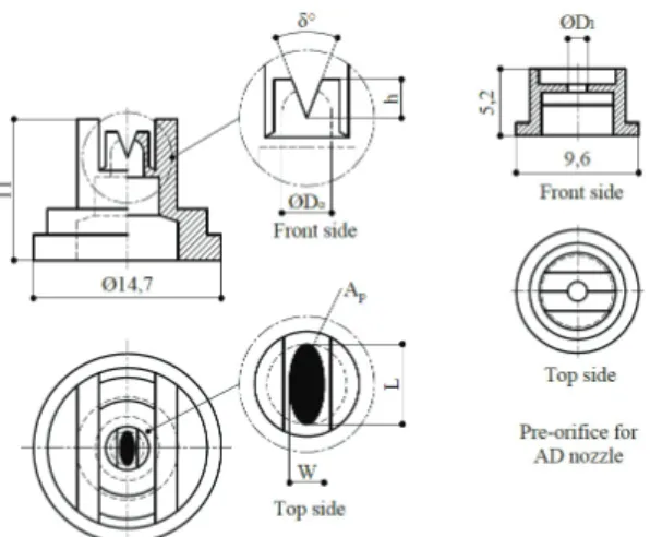
In this study, two different types of flat-fan nozzles with different nominal sizes were used: multi-range flat-fan nozzles (LU120015, LU12003 and LU12005, Lechler GmbH) and anti-drift flat-fan nozzles (AD120015, AD12003 and AD12004, Lechler GmbH). Technical properties of the nozzles are given at Table 1. The dimensional properties measured using stereo zoom microscope (Olympus SZ60, JP) equipped with micrometer were displayed on Figure 1.
Figure 1- Dimensions of AD and LU flat-fan nozzles
(δ°, V-slot angle; h, V-slot height; ØDo, entry orifice
diameter; ØD1, diameter of hole on pre-orifice
plate; Ap, projected area; L, orifice major length;W,
orifice minor length)
Şekil 1- AD ve LU tip yelpaze hüzmeli memelerin
ölçüleri (δ°, V-yarık açısı; h, V-yarık yüksekliği; ØDo,
giriş orifisi çapı; ØD1, ön orifis plakası delik çapı;
Ap, izdüşüm alanı; L, orifisin en büyük uzunluğu; W,
561
Ta r ı m B i l i m l e r i D e r g i s i – J o u r n a l o f A g r i c u l t u r a l S c i e n c e s 21 (2015) 558-571
Table 1- Technical properties of multi-range (LU) and anti-drift (AD) flat-fan nozzles (Qnom, nominal flow
rate; α°, spray angle; W, orifice minor length; L, orifice major length; δ°, V-slot angle; ØDo,, entry orifice
diameter; ØD1, diameter of hole on pre-orifice plate; h, V-slot height; Ap, projected area)
Çizelge 1- Yüksek etki alanlı (LU) ve düşük sürüklenme potansiyelli (AD) yelpaze hüzmeli memelerin teknik
özellikleri (Qnom, nominal debi; α°, püskürtme açısı; W, orifisin en küçük uzunluğu; L, orifisin en büyük uzunluğu; δ°,
V-yarık açısı; ØDo, giriş orifisi çapı; ØD1, ön orifis plakası delik çapı; h, V-yarık yüksekliği; Ap, izdüşüm alanı)
Technical
properties Multi-range flat-fan nozzles Anti-drift flat-fan nozzles
LU120015 LU12003 LU12005 AD120015 AD12003 AD12004
Material* POM POM POM POM POM POM
Color Green Blue Brown Green Blue Red
Qnom (gal min-1) 0.15 0.30 0.50 0.15 0.30 0.40
Qnom (L min-1)† 0.57 1.14 1.89 0.57 1.14 1.51 α (°) 120° 120° 120° 120° 120° 120° W (mm) ‡ 0.38 0.42 0.65 0.48 0.62 0.68 L (mm)‡ 1.70 2.20 2.60 2.20 2.60 2.80 W (mm) 0.33 0.42 0.67 0.35 0.51 0.66 L (mm) 1.54 2.35 2.60 1.90 2.70 2.70 δ (°) 19.4° 15.4° 29.7° 15.0° 20.4° 25.9° ØDO (mm) 1.54 2.35 2.60 1.90 2.70 2.70 ØD1 (mm) - - - 0.96 1.36 1.47 h (mm) 1.42 1.89 2.12 1.56 1.62 1.57 Ap (mm2) 0.422 0.828 1.370 0.564 1.100 1.435
*, polyoxymethylene; †, Qnom (L min-1) = [3.785 × Qnom (gal min-1)]; ‡, manufacturer data (Lechler GmbH)
3D-solid modelling of a flat-fan nozzle was generated using AutoCAD software (version 2015) in reference to the technical sizes of a nozzle in order to determine the projected area of the flat-fan nozzle orifice (Figure 2a). After the solid modelling, the nozzle was sectioned at longitudinal orientation (Figure 2b) and 2D-copy of surface covering half of
the V-slotted orifice (Figure 2c) was revealed. The opening’s surface area (As), which is semi elliptical, was measured using “area” command of the software (Figure 2d). The projected area (Ap) of the orifice based on the half of the surface area of the orifice was calculated using Equation (1) (Zhou et al 1996):
4
Figure 1- Dimensions of AD and LU flat-fan nozzles (δ°, V-slot angle; h, V-slot height; ØDo,entry orifice
diameter; ØD1, diameter of hole on pre-orifice plate; Ap, projected area; L, orifice major length;W,
orifice minor length)
Şekil 1- AD ve LU tip yelpaze huzmeli memelerin ölçüleri (δ°, V-yarık açısı; h, V-yarık yüksekliği; ØDo, giriş
orifisi çapı; ØD1, ön orifis plakası delik çapı; Ap, izdüşüm alanı; L, orifisin en büyük uzunluğu; W, orifisin en
küçük uzunluğu)
3D-solid modelling of a flat-fan nozzle was generated using AutoCAD software (version 2015) in reference to the technical sizes of a nozzle in order to determine the projected area of the flat-fan nozzle orifice (Figure 2a). After the solid modelling, the nozzle was sectioned at longitudinal orientation (Figure 2b) and 2D-copy of surface covering half of the V-slotted orifice (Figure 2c) was revealed. The opening’s surface area (As), which is semi elliptical, was measured using “area” command of the software (Figure
2d). The projected area (Ap) of the orifice based on the half of the surface area of the orifice was
calculated using Equation (1) (Zhou et al 1996):
𝐴𝐴𝐴𝐴𝑝𝑝𝑝𝑝= 2 ∙ 𝐴𝐴𝐴𝐴𝑠𝑠𝑠𝑠∙ 𝑠𝑠𝑠𝑠𝑠𝑠𝑠𝑠𝑠𝑠𝑠𝑠 �𝛿𝛿𝛿𝛿2� (1) (1)
(a) (b) (c) (d)
Figure 2- Determination of the projected area of a fan nozzle orifice opening; a, 3D-modelling of a flat-fan nozzle; b, section of the orifice at longitudinal orientation; c, 2D-copy of surface covering half of the
V-slotted orifice; d, area of As orifice which is half of the opening area of the orifice
Şekil 2- Yelpaze hüzmeli bir meme orifis açıklığının izdüşüm alanının belirlenmesi; a, yelpaze hüzmeli bir memenin üç boyutlu modellenmesi; b, boyuna oryastasyonda orifis kesiti; c, V-yarıklı orifisin yarısını kaplayan yüzeyin iki
562
Ta r ı m B i l i m l e r i D e r g i s i – J o u r n a l o f A g r i c u l t u r a l S c i e n c e s 21 (2015) 558-571 2.2. Nozzle strainersThe flat-fan nozzles were used with four different types of strainers: three cylindrical strainers of 40-mesh, 50-mesh and 80-mesh screen sizes; two ball-check cylindrical strainers of 50 and 80 mesh screen sizes; a slotted strainer of 50 mesh screen size; a screen type cup strainer of 50 mesh screen size. Table 2 shows technical properties of the strainers.
Their dimensional properties were displayed on drawings in Figure 3.
2.3. Sprayer and power unit
Trials were conducted using a conventional field sprayer (TP 200 Piton, Taral®, Istanbul, TR) with a 200-liters polyethylene tank. The sprayer had a spray boom of 6.0- meters. There were twelve triplets nozzle holders spaced 50 cm apart on the
Table 2- Technical properties of strainer types
Çizelge 2- Süzgeç tiplerinin teknik özellikleri Technical
properties Cylindrical strainers Ball-check strainers strainer Slotted 50 mesh
Cup screen strainer 50 mesh 40 mesh 50 mesh 80 mesh 50 mesh 80 mesh
Screen material Cr-Ni Cr-Ni Stainless
steel Cr-Ni Stainless steel Brass Cr-Ni Type Screen Screen Perforated
sheet Screen Perforated sheet Slotted Screen Screen shape Square
(0.5×0.5) (0.3×0.3)Square Hexagon (0.3×0.3)Square Hexagon Slot (0.3 mm) Total: 8 (0.3×0.3)Square Screen pattern
Body material POM POM POM POM POM Brass POM
Number of
openings per cm2 225 361 238 361 238 - 361
Number of
openings per cm 15 19 Hor:14; Ver:17 19 Hor.:14; Ver.:17 - 19 Diameter of screen wire (mm) 0.18 0.18 - 0.18 - - 0.18 Total area of an opening on strainer body (mm2) 0.237 0.120 0.056 0.120 0.056 4.050 0.120 Opening area per
cm2 (mm2) 53.3 43.3 13.3 43.3 13.3 - 43.3
Strainers body entry opening area (ΣOA, mm2)
20.0 24.0 12.0 24.0 12.0 32.0 78.5
Strainers body exit
563
Ta r ı m B i l i m l e r i D e r g i s i – J o u r n a l o f A g r i c u l t u r a l S c i e n c e s 21 (2015) 558-571
dry boom. A pressure regulator (max. 40 bar, 90 L min-1, RG-7 Model) ensured the adjustment of
the operational pressure. The pressure indicator of the manometer ranged from 0.5 to 25 bars. An electric motor (2.2 kW, 1405 min-1, AGM 100L 4a
type, Gamak, Istanbul, TR) was used to drive the sprayer pump shaft (500 min-1, 30 L min-1, 39.2 bar,
Tar30 type, Taral®, Istanbul, TR). A belt-pulley
mechanism provided rotation transmission from the electric motor shaft to pump, and the transmission to pump shaft was decreased in the rate of 1/2.8.
2.4. Determination of nozzle flow rate
Flow rates of the nozzles used with each of four different types of the strainers were measured at the operational pressures of 1.5, 3.0, 4.0, 6.0 and
7
Cylindrical strainers of 40- and 50-meshes
screen sizes
Perforated sheet type cylindricalstrainer of 80-mesh screen size
Ball-check type cylindrical strainer of 50-mesh screen size
Ball-check type cylindricalstrainer of 80-mesh screen size
Slotted type strainer
of 50 mesh screen size Cup screen type strainerof 50 mesh screen size
Figure 3- Dimensions of the strainer types Şekil 3- Süzgeç tiplerinin ölçüleri
2.3. Sprayer and power unit
Trials were conducted using a conventional field sprayer (TP 200 Piton, Taral®, Istanbul, TR) with a 200-liters polyethylene tank. The sprayer had aspray boom of 6.0- meters. There were twelve triplets
nozzle holders spaced 50 cm apart on the dry boom. A pressure regulator (max. 40 bar, 90 L min-1, RG-7
Model) ensured the adjustment of the operational pressure. The pressure indicator of the manometer
ranged from 0.5 to 25 bars. An electric motor (2.2 kW, 1405 min-1, AGM 100L 4a type, Gamak, Istanbul,
TR) was used to drive the sprayer pump shaft (500 min-1, 30 L min-1, 39.2 bar, Tar30 type, Taral®,
Istanbul, TR). A belt-pulley mechanism provided rotation transmission from the electric motor shaft to pump, and the transmission to pump shaft was decreased in the rate of 1/2.8.
2.4. Determination of nozzle flow rate
Flow rates of the nozzles used with each of four different types of the strainers were measured at the operational pressures of 1.5, 3.0, 4.0, 6.0 and 8.0 bars. These measurements were also obtained without using strainers. In the trials, six nozzles for each nominal size of the nozzles were used. The measurements were replicated five times for each combination of nozzle size, nozzle type, and strainer Figure 3- Dimensions of the strainer types
564
Ta r ı m B i l i m l e r i D e r g i s i – J o u r n a l o f A g r i c u l t u r a l S c i e n c e s 21 (2015) 558-5718.0 bars. These measurements were also obtained without using strainers. In the trials, six nozzles for each nominal size of the nozzles were used. The measurements were replicated five times for each combination of nozzle size, nozzle type, and strainer type using a flow meter (Nozzle calibrator, 0.08-3.79 L min-1, ±2.5% accuracy, SC-1 Model, SpotOn®,
IL). Spray liquid was tap water and sprayer tank was continuously filled with water. Temperature and relative moisture of indoor ranged from 16.0 °C to 18.4 °C, and 32% to 52%, respectively. The mean temperature of spraying liquid measured from a location that is near to the exit orifice of nozzle was 15 °C.
2.5. Relation between the nozzle flow rate and spray pressure
In the preliminary tests, pressure fluctuations between the pressure regulator and nozzle holder on boom spray line were observed. Therefore, to sensitively reveal the relation between the flow rate and spray pressure for each combination of the
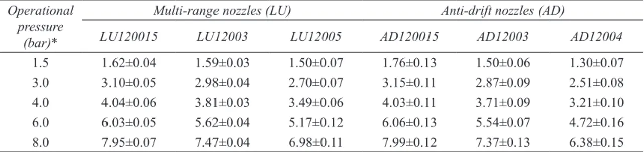
nozzle size, nozzle type, and strainer type, spray pressure was measured after adjusting the operating pressure. A digital manometer (Ref D2, 0.1%, 0-400 bar, SİKA GmbH & Co. KG), mounted between nozzle holder and cap determined the spray pressure of each nozzle combination. The mean values of spray pressures with regard to the operational pressures were given at Table 3.
In order to reveal the relation between the nozzle flow rate and spray pressure, a power regression model which is defined as the equation of Q= k∙Pn, was used. The “k” is known as orifice coefficient in reference to ASABE Standards (2009), and the slope of the line or curve displaying the relation between the dependent (flow rate) and independent (spray pressure) variables. The “n” is exponent coefficient of spray pressure and theoretically known as 0.50. The effects of the nozzle types, orifice sizes, and strainer types on LU and AD nozzles’ flow characteristics were tested based on their orifice coefficient (k) and exponent coefficient (n) of the spray pressure.
Table 3- Spray liquid pressure measured between the nozzle holder and cap location after regulating the operational pressure (bar, mean ± standard deviation)
Çizelge 3- İşletme basıncı ayarlandıktan sonra meme gövdesi ve başlığı arasında ölçülen akışkan basıncı (bar, ortalama ± standart sapma)
Operational pressure
(bar)*
Multi-range nozzles (LU) Anti-drift nozzles (AD)
LU120015 LU12003 LU12005 AD120015 AD12003 AD12004
1.5 1.62±0.04 1.59±0.03 1.50±0.07 1.76±0.13 1.50±0.06 1.30±0.07 3.0 3.10±0.05 2.98±0.04 2.70±0.07 3.15±0.11 2.87±0.09 2.51±0.08 4.0 4.04±0.06 3.81±0.03 3.49±0.06 4.03±0.11 3.71±0.09 3.21±0.10 6.0 6.03±0.05 5.62±0.04 5.17±0.12 6.06±0.13 5.54±0.07 4.72±0.16 8.0 7.95±0.07 7.47±0.04 6.98±0.11 7.99±0.12 7.37±0.13 6.38±0.15
*, spray pressure values adjusted by using a regulatory
2.6. Flow rate deviation of individual nozzle
The flow rate deviation limits of a nozzle should range within ±10% as defined in American Society of Agricultural and Biological Engineers Standards (ASABE Standards 2006). Flow rate deviation of individual nozzle was calculated using Equation (2)
(Huyghebaert et al 2001). The flow rate deviation marked positive denoted that the actual flow rate exceed the nominal flow rate of the nozzle, while negative marks showed that the measured flow rate was lower than that of the nominal flow rate of the nozzle. Likewise, the deviation limits of the flow rate at the confidence interval of 99% were
565
Ta r ı m B i l i m l e r i D e r g i s i – J o u r n a l o f A g r i c u l t u r a l S c i e n c e s 21 (2015) 558-571
separately tabulated based on their orifice size and strainer type in reference to the nozzle type.
9
𝜑𝜑𝜑𝜑 = �𝑄𝑄𝑄𝑄𝑎𝑎𝑎𝑎𝑎𝑎𝑎𝑎𝑎𝑎𝑎𝑎−𝑄𝑄𝑄𝑄𝑛𝑛𝑛𝑛𝑛𝑛𝑛𝑛𝑛𝑛𝑛𝑛
𝑄𝑄𝑄𝑄𝑛𝑛𝑛𝑛𝑛𝑛𝑛𝑛𝑛𝑛𝑛𝑛 � ∙ 100 (2)
2.7. Determination of the discharge coefficient
The theoretical flow rate was calculated using Equation (3) based on spray pressure (Srivastava et al 1993; Ballester & Dopazo 1994; Rashid et al 2012; Yu et al 2013):
𝑄𝑄𝑄𝑄𝑡𝑡𝑡𝑡ℎ𝑒𝑒𝑒𝑒𝑒𝑒𝑒𝑒= 𝐴𝐴𝐴𝐴 ∙ 𝑉𝑉𝑉𝑉 = 𝐴𝐴𝐴𝐴 ∙ �2∆𝑃𝑃𝑃𝑃𝜌𝜌𝜌𝜌� 𝑛𝑛𝑛𝑛
(3) The “n” coefficient, exponent of the spray pressure, taken account of the Equation (3) was 0.50 theoretically. Discharge coefficient (Cd), which is the ratio of the actual flow rate to the theoretical flow
rate, was also calculated based on Equation (4) (Srivastava et al 1993). The density of spray liquid, temperature of which is 15 °C, was settled for 999.1 kg m-3.
𝐶𝐶𝐶𝐶𝑑𝑑𝑑𝑑=𝑄𝑄𝑄𝑄𝑄𝑄𝑄𝑄𝑎𝑎𝑎𝑎ℎ𝑒𝑒𝑒𝑒𝑛𝑛𝑛𝑛𝑎𝑎𝑎𝑎𝑎𝑎𝑎𝑎𝑎𝑎𝑎𝑎 (4)
2.8. Statistical analysis
The orifice coefficient (k) and pressure exponent coefficient (n) data were obtained using the power regression analysis in SPSS statistical software. ANOVA (Analysis of Variance) test was performed to reveal the effects of the nozzle types used with the strainer types at different operational pressure onflow characteristics. A completely randomized design and SPSS statistical software were used for analysis of variance with a 95% confidence level (P= 0.05) and Duncan’s Multiple Range comparison test to determine the significant differences.
3. Results and Discussion
3.1. Evaluation of orifice coefficient (k)
The power regression model (𝑄𝑄𝑄𝑄 = 𝑘𝑘𝑘𝑘 ∙ 𝑃𝑃𝑃𝑃𝑛𝑛𝑛𝑛) explains the relation between the volumetric flow rate (Q) and
spray pressure (P) of a nozzle, where “k” is the orifice coefficient, and “n” is the exponent coefficient of the spray pressure.
The variation of the orifice coefficient (k) and exponent of the spray pressure (n) with regard to orifice sizes of the anti-drift (AD) and multi-range (LU) flat-fan nozzles used with different types of the strainers were given in the Table 4. AD nozzle used without strainer had the highest “k” mean value. The “k” mean values of LU nozzle without strainer were statistically the same as for those with the cup and slotted strainers, and cylindrical strainers of 40-mesh. Remarkably, the nozzles with ball-check strainers had the lowest “k” mean value as compared to the other strainers. Among the nozzle types, it was seen that the
“k” mean values of LU nozzle were higher than those of AD nozzle for all strainer types.
The volumetric flow rate of a spray nozzle is proportional to the square root of the spray pressure. Orifice coefficient, referred as “k” (ASABE Standards 2009), is the ratio of flow rate to the square root of spray pressure and the slope of the line clarifying the relation between the flow rate and spray pressure. The “k” might be an important comparison variable revealing the distinction between the flow characteristics of optimized nozzles which have different design features. Thus, the “k” mean values of the LU and AD nozzles used with ball-check strainers was lower than those of the cup screen, slotted and cylindrical strainers and without strainer.
3.2. Evaluation of exponent coefficient (n) of the spray pressure
While the mean values of “n” coefficient of the AD and LU nozzles used with the ball-check strainers were higher than 0.50, the mean values of the other strainer types were found notably close to 0.50 (Table 4). In general, the effect of orifice size on the “n” coefficient was statistically insignificant (P>0.05). For both nozzle types, the usage of ball-check strainer of 80-meshgave a higher “n” mean value as compared
(2)
2.7. Determination of the discharge coefficient
The theoretical flow rate was calculated using Equation (3) based on spray pressure (Srivastava et al 1993; Ballester & Dopazo 1994; Rashid et al 2012; Yu et al 2013):
9
𝜑𝜑𝜑𝜑 = �𝑄𝑄𝑄𝑄𝑎𝑎𝑎𝑎𝑎𝑎𝑎𝑎𝑎𝑎𝑎𝑎−𝑄𝑄𝑄𝑄𝑛𝑛𝑛𝑛𝑛𝑛𝑛𝑛𝑛𝑛𝑛𝑛
𝑄𝑄𝑄𝑄𝑛𝑛𝑛𝑛𝑛𝑛𝑛𝑛𝑛𝑛𝑛𝑛 � ∙ 100 (2)
2.7. Determination of the discharge coefficient
The theoretical flow rate was calculated using Equation (3) based on spray pressure (Srivastava et al 1993; Ballester & Dopazo 1994; Rashid et al 2012; Yu et al 2013):
𝑄𝑄𝑄𝑄𝑡𝑡𝑡𝑡ℎ𝑒𝑒𝑒𝑒𝑒𝑒𝑒𝑒= 𝐴𝐴𝐴𝐴 ∙ 𝑉𝑉𝑉𝑉 = 𝐴𝐴𝐴𝐴 ∙ �2∆𝑃𝑃𝑃𝑃𝜌𝜌𝜌𝜌� 𝑛𝑛𝑛𝑛
(3) The “n” coefficient, exponent of the spray pressure, taken account of the Equation (3) was 0.50 theoretically. Discharge coefficient (Cd), which is the ratio of the actual flow rate to the theoretical flow
rate, was also calculated based on Equation (4) (Srivastava et al 1993). The density of spray liquid, temperature of which is 15 °C, was settled for 999.1 kg m-3.
𝐶𝐶𝐶𝐶𝑑𝑑𝑑𝑑=𝑄𝑄𝑄𝑄𝑄𝑄𝑄𝑄𝑎𝑎𝑎𝑎ℎ𝑒𝑒𝑒𝑒𝑛𝑛𝑛𝑛𝑎𝑎𝑎𝑎𝑎𝑎𝑎𝑎𝑎𝑎𝑎𝑎 (4)
2.8. Statistical analysis
The orifice coefficient (k) and pressure exponent coefficient (n) data were obtained using the power regression analysis in SPSS statistical software. ANOVA (Analysis of Variance) test was performed to reveal the effects of the nozzle types used with the strainer types at different operational pressure onflow characteristics. A completely randomized design and SPSS statistical software were used for analysis of variance with a 95% confidence level (P= 0.05) and Duncan’s Multiple Range comparison test to determine the significant differences.
3. Results and Discussion
3.1. Evaluation of orifice coefficient (k)
The power regression model (𝑄𝑄𝑄𝑄 = 𝑘𝑘𝑘𝑘 ∙ 𝑃𝑃𝑃𝑃𝑛𝑛𝑛𝑛) explains the relation between the volumetric flow rate (Q) and
spray pressure (P) of a nozzle, where “k” is the orifice coefficient, and “n” is the exponent coefficient of the spray pressure.
The variation of the orifice coefficient (k) and exponent of the spray pressure (n) with regard to orifice sizes of the anti-drift (AD) and multi-range (LU) flat-fan nozzles used with different types of the strainers were given in the Table 4. AD nozzle used without strainer had the highest “k” mean value. The “k” mean values of LU nozzle without strainer were statistically the same as for those with the cup and slotted strainers, and cylindrical strainers of 40-mesh. Remarkably, the nozzles with ball-check strainers had the lowest “k” mean value as compared to the other strainers. Among the nozzle types, it was seen that the
“k” mean values of LU nozzle were higher than those of AD nozzle for all strainer types.
The volumetric flow rate of a spray nozzle is proportional to the square root of the spray pressure. Orifice coefficient, referred as “k” (ASABE Standards 2009), is the ratio of flow rate to the square root of spray pressure and the slope of the line clarifying the relation between the flow rate and spray pressure. The “k” might be an important comparison variable revealing the distinction between the flow characteristics of optimized nozzles which have different design features. Thus, the “k” mean values of the LU and AD nozzles used with ball-check strainers was lower than those of the cup screen, slotted and cylindrical strainers and without strainer.
3.2. Evaluation of exponent coefficient (n) of the spray pressure
While the mean values of “n” coefficient of the AD and LU nozzles used with the ball-check strainers were higher than 0.50, the mean values of the other strainer types were found notably close to 0.50 (Table 4). In general, the effect of orifice size on the “n” coefficient was statistically insignificant (P>0.05). For both nozzle types, the usage of ball-check strainer of 80-meshgave a higher “n” mean value as compared
(3) The “n” coefficient, exponent of the spray pressure, taken account of the Equation (3) was 0.50 theoretically. Discharge coefficient (Cd), which is the ratio of the actual flow rate to the theoretical flow rate, was also calculated based on Equation (4) (Srivastava et al 1993). The density of spray liquid, temperature of which is 15 °C, was settled for 999.1 kg m-3.
9
𝜑𝜑𝜑𝜑 = �𝑄𝑄𝑄𝑄𝑎𝑎𝑎𝑎𝑎𝑎𝑎𝑎𝑎𝑎𝑎𝑎−𝑄𝑄𝑄𝑄𝑛𝑛𝑛𝑛𝑛𝑛𝑛𝑛𝑛𝑛𝑛𝑛
𝑄𝑄𝑄𝑄𝑛𝑛𝑛𝑛𝑛𝑛𝑛𝑛𝑛𝑛𝑛𝑛 � ∙ 100 (2)
2.7. Determination of the discharge coefficient
The theoretical flow rate was calculated using Equation (3) based on spray pressure (Srivastava et al 1993; Ballester & Dopazo 1994; Rashid et al 2012; Yu et al 2013):
𝑄𝑄𝑄𝑄𝑡𝑡𝑡𝑡ℎ𝑒𝑒𝑒𝑒𝑒𝑒𝑒𝑒= 𝐴𝐴𝐴𝐴 ∙ 𝑉𝑉𝑉𝑉 = 𝐴𝐴𝐴𝐴 ∙ �2∆𝑃𝑃𝑃𝑃𝜌𝜌𝜌𝜌� 𝑛𝑛𝑛𝑛
(3) The “n” coefficient, exponent of the spray pressure, taken account of the Equation (3) was 0.50 theoretically. Discharge coefficient (Cd), which is the ratio of the actual flow rate to the theoretical flow
rate, was also calculated based on Equation (4) (Srivastava et al 1993). The density of spray liquid, temperature of which is 15 °C, was settled for 999.1 kg m-3.
𝐶𝐶𝐶𝐶𝑑𝑑𝑑𝑑=𝑄𝑄𝑄𝑄𝑄𝑄𝑄𝑄𝑎𝑎𝑎𝑎ℎ𝑒𝑒𝑒𝑒𝑛𝑛𝑛𝑛𝑎𝑎𝑎𝑎𝑎𝑎𝑎𝑎𝑎𝑎𝑎𝑎 (4)
2.8. Statistical analysis
The orifice coefficient (k) and pressure exponent coefficient (n) data were obtained using the power regression analysis in SPSS statistical software. ANOVA (Analysis of Variance) test was performed to reveal the effects of the nozzle types used with the strainer types at different operational pressure onflow characteristics. A completely randomized design and SPSS statistical software were used for analysis of variance with a 95% confidence level (P= 0.05) and Duncan’s Multiple Range comparison test to determine the significant differences.
3. Results and Discussion
3.1. Evaluation of orifice coefficient (k)
The power regression model (𝑄𝑄𝑄𝑄 = 𝑘𝑘𝑘𝑘 ∙ 𝑃𝑃𝑃𝑃𝑛𝑛𝑛𝑛) explains the relation between the volumetric flow rate (Q) and
spray pressure (P) of a nozzle, where “k” is the orifice coefficient, and “n” is the exponent coefficient of the spray pressure.
The variation of the orifice coefficient (k) and exponent of the spray pressure (n) with regard to orifice sizes of the anti-drift (AD) and multi-range (LU) flat-fan nozzles used with different types of the strainers were given in the Table 4. AD nozzle used without strainer had the highest “k” mean value. The “k” mean values of LU nozzle without strainer were statistically the same as for those with the cup and slotted strainers, and cylindrical strainers of 40-mesh. Remarkably, the nozzles with ball-check strainers had the lowest “k” mean value as compared to the other strainers. Among the nozzle types, it was seen that the
“k” mean values of LU nozzle were higher than those of AD nozzle for all strainer types.
The volumetric flow rate of a spray nozzle is proportional to the square root of the spray pressure. Orifice coefficient, referred as “k” (ASABE Standards 2009), is the ratio of flow rate to the square root of spray pressure and the slope of the line clarifying the relation between the flow rate and spray pressure. The “k” might be an important comparison variable revealing the distinction between the flow characteristics of optimized nozzles which have different design features. Thus, the “k” mean values of the LU and AD nozzles used with ball-check strainers was lower than those of the cup screen, slotted and cylindrical strainers and without strainer.
3.2. Evaluation of exponent coefficient (n) of the spray pressure
While the mean values of “n” coefficient of the AD and LU nozzles used with the ball-check strainers were higher than 0.50, the mean values of the other strainer types were found notably close to 0.50 (Table 4). In general, the effect of orifice size on the “n” coefficient was statistically insignificant (P>0.05). For both nozzle types, the usage of ball-check strainer of 80-meshgave a higher “n” mean value as compared
(4)
2.8. Statistical analysis
The orifice coefficient (k) and pressure exponent coefficient (n) data were obtained using the power regression analysis in SPSS statistical software. ANOVA (Analysis of Variance) test was performed to reveal the effects of the nozzle types used with the strainer types at different operational pressure on flow characteristics. A completely randomized design and SPSS statistical software were used for analysis of variance with a 95% confidence level (P= 0.05) and Duncan’s Multiple Range comparison test to determine the significant differences.
3. Results and Discussion
3.1. Evaluation of orifice coefficient (k)
The power regression model
9
𝜑𝜑𝜑𝜑 = �𝑄𝑄𝑄𝑄𝑎𝑎𝑎𝑎𝑎𝑎𝑎𝑎𝑎𝑎𝑎𝑎−𝑄𝑄𝑄𝑄𝑛𝑛𝑛𝑛𝑛𝑛𝑛𝑛𝑛𝑛𝑛𝑛
𝑄𝑄𝑄𝑄𝑛𝑛𝑛𝑛𝑛𝑛𝑛𝑛𝑛𝑛𝑛𝑛 � ∙ 100 (2)
2.7. Determination of the discharge coefficient
The theoretical flow rate was calculated using Equation (3) based on spray pressure (Srivastava et al 1993; Ballester & Dopazo 1994; Rashid et al 2012; Yu et al 2013):
𝑄𝑄𝑄𝑄𝑡𝑡𝑡𝑡ℎ𝑒𝑒𝑒𝑒𝑒𝑒𝑒𝑒= 𝐴𝐴𝐴𝐴 ∙ 𝑉𝑉𝑉𝑉 = 𝐴𝐴𝐴𝐴 ∙ �2∆𝑃𝑃𝑃𝑃𝜌𝜌𝜌𝜌� 𝑛𝑛𝑛𝑛
(3) The “n” coefficient, exponent of the spray pressure, taken account of the Equation (3) was 0.50 theoretically. Discharge coefficient (Cd), which is the ratio of the actual flow rate to the theoretical flow
rate, was also calculated based on Equation (4) (Srivastava et al 1993). The density of spray liquid, temperature of which is 15 °C, was settled for 999.1 kg m-3.
𝐶𝐶𝐶𝐶𝑑𝑑𝑑𝑑=𝑄𝑄𝑄𝑄𝑄𝑄𝑄𝑄𝑎𝑎𝑎𝑎ℎ𝑒𝑒𝑒𝑒𝑛𝑛𝑛𝑛𝑎𝑎𝑎𝑎𝑎𝑎𝑎𝑎𝑎𝑎𝑎𝑎 (4)
2.8. Statistical analysis
The orifice coefficient (k) and pressure exponent coefficient (n) data were obtained using the power regression analysis in SPSS statistical software. ANOVA (Analysis of Variance) test was performed to reveal the effects of the nozzle types used with the strainer types at different operational pressure onflow characteristics. A completely randomized design and SPSS statistical software were used for analysis of variance with a 95% confidence level (P= 0.05) and Duncan’s Multiple Range comparison test to determine the significant differences.
3. Results and Discussion
3.1. Evaluation of orifice coefficient (k)
The power regression model (𝑄𝑄𝑄𝑄 = 𝑘𝑘𝑘𝑘 ∙ 𝑃𝑃𝑃𝑃𝑛𝑛𝑛𝑛) explains the relation between the volumetric flow rate (Q) and
spray pressure (P) of a nozzle, where “k” is the orifice coefficient, and “n” is the exponent coefficient of the spray pressure.
The variation of the orifice coefficient (k) and exponent of the spray pressure (n) with regard to orifice sizes of the anti-drift (AD) and multi-range (LU) flat-fan nozzles used with different types of the strainers were given in the Table 4. AD nozzle used without strainer had the highest “k” mean value. The “k” mean values of LU nozzle without strainer were statistically the same as for those with the cup and slotted strainers, and cylindrical strainers of 40-mesh. Remarkably, the nozzles with ball-check strainers had the lowest “k” mean value as compared to the other strainers. Among the nozzle types, it was seen that the
“k” mean values of LU nozzle were higher than those of AD nozzle for all strainer types.
The volumetric flow rate of a spray nozzle is proportional to the square root of the spray pressure. Orifice coefficient, referred as “k” (ASABE Standards 2009), is the ratio of flow rate to the square root of spray pressure and the slope of the line clarifying the relation between the flow rate and spray pressure. The “k” might be an important comparison variable revealing the distinction between the flow characteristics of optimized nozzles which have different design features. Thus, the “k” mean values of the LU and AD nozzles used with ball-check strainers was lower than those of the cup screen, slotted and cylindrical strainers and without strainer.
3.2. Evaluation of exponent coefficient (n) of the spray pressure
While the mean values of “n” coefficient of the AD and LU nozzles used with the ball-check strainers were higher than 0.50, the mean values of the other strainer types were found notably close to 0.50 (Table 4). In general, the effect of orifice size on the “n” coefficient was statistically insignificant (P>0.05). For both nozzle types, the usage of ball-check strainer of 80-meshgave a higher “n” mean value as compared
explains the relation between the volumetric flow rate (Q) and spray pressure (P) of a nozzle, where “k” is the orifice coefficient, and “n” is the exponent coefficient of the spray pressure.
The variation of the orifice coefficient (k) and exponent of the spray pressure (n) with regard to orifice sizes of the anti-drift (AD) and multi-range (LU) flat-fan nozzles used with different types of the strainers were given in the Table 4. AD nozzle used without strainer had the highest “k” mean value. The “k” mean values of LU nozzle without strainer were statistically the same as for those with the cup and slotted strainers, and cylindrical strainers of 40-mesh. Remarkably, the nozzles with ball-check strainers had the lowest “k” mean value as compared to the other strainers. Among the nozzle types, it was seen that the “k” mean values of LU nozzle were higher than those of AD nozzle for all strainer types.
The volumetric flow rate of a spray nozzle is proportional to the square root of the spray pressure. Orifice coefficient, referred as “k” (ASABE Standards 2009), is the ratio of flow rate to the square root of spray pressure and the slope of the line clarifying the relation between the flow rate and spray pressure. The “k” might be an important comparison variable revealing the distinction between the flow characteristics of optimized nozzles which have different design features. Thus, the “k” mean values of the LU and AD nozzles used with ball-check strainers was lower than those of the cup screen, slotted and cylindrical strainers and without strainer.
3.2. Evaluation of exponent coefficient (n) of the spray pressure
While the mean values of “n” coefficient of the AD and LU nozzles used with the ball-check strainers were higher than 0.50, the mean values of the other strainer types were found notably close to 0.50 (Table 4). In general, the effect of orifice size on the “n” coefficient was statistically insignificant (P>0.05). For both nozzle types, the usage of ball-check strainer of 80-mesh gave a higher “n” mean value as compared to the ball-check strainer of 50-mesh (Table 4). Both of the ball-check strainers had higher “n” mean values than those of the other strainers. The “n” coefficient mean values of the nozzles used with or without strainer remarkably increased as the orifice size increased.
566
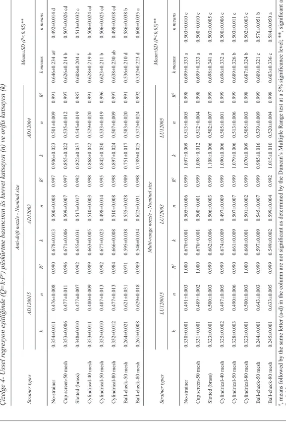
Ta r ı m B i l i m l e r i D e r g i s i – J o u r n a l o f A g r i c u l t u r a l S c i e n c e s 21 (2015) 558-571Table 4- Orifice coefficient (k) and exponent coefficient (n) of spray pr
essur e in the power r egr ession model of Q=k∙P n Çizelge 4- Üssel r egr esyon eşitliğinde (Q=k∙P n) püskürtme basıncın
ın üs kuvvet katsayısı (n) ve orifis katsayısı (k)
Strainer types
Anti-drift nozzle - Nominal size
Mean±SD (P<0.05)** AD120015 AD12003 AD12004 k n R 2 k n R 2 k n R 2 k means n means No-strainer 0.354±0.01 1 0.476±0.008 0.990 0.678±0.013 0.500±0.008 0.997 0.906±0.023 0.501±0.009 0.991 0.646±0.234 a# 0.492±0.014 d
Cup screen-50 mesh
0.353±0.006 0.477±0.01 1 0.996 0.671±0.006 0.509±0.007 0.997 0.855±0.022 0.535±0.012 0.997 0.626±0.214 b 0.507±0.026 cd Slotted (brass) 0.348±0.010 0.477±0.007 0.992 0.655±0.031 0.517±0.017 0.992 0.822±0.037 0.545±0.019 0.987 0.608±0.204 c 0.513±0.032 c Cylindrical-40 mesh 0.353±0.01 1 0.480±0.009 0.989 0.663±0.005 0.510±0.003 0.998 0.868±0.042 0.529±0.020 0.991 0.628±0.219 b 0.506±0.024 cd Cylindrical-50 mesh 0.352±0.010 0.487±0.013 0.992 0.677±0.023 0.498±0.014 0.995 0.842±0.030 0.533±0.019 0.996 0.623±0.21 1 b 0.506±0.025 cd Cylindrical-80 mesh 0.352±0.012 0.477±0.013 0.984 0.666±0.008 0.510±0.008 0.998 0.897±0.024 0.507±0.009 0.997 0.638±0.230 ab 0.498±0.018 cd Ball-check-50 mesh 0.264±0.021 0.621±0.031 0.971 0.595±0.038 0.555±0.028 0.989 0.751±0.017 0.583±0.020 0.991 0.536±0.210 d 0.586±0.038 b Ball-check-80 mesh 0.261±0.008 0.629±0.018 0.989 0.546±0.034 0.622±0.031 0.998 0.789±0.025 0.572±0.024 0.992 0.532±0.223 d 0.608±0.035 a Strainer types
Multi-range nozzle - Nominal size
Mean±SD (P<0.05)** LU120015 LU12003 LU12005 k n R 2 k n R 2 k n R 2 k means n means No-strainer 0.330±0.001 0.491±0.003 1.000 0.670±0.001 0.505±0.006 0.999 1.097±0.009 0.513±0.005 0.998 0.699±0.333 a 0.503±0.010 c
Cup screen-50 mesh
0.331±0.001 0.489±0.002 1.000 0.670±0.001 0.500±0.001 0.999 1.098±0.012 0.512±0.004 0.998 0.699±0.333 a 0.500±0.010 c Slotted (brass) 0.323±0.001 0.500±0.003 0.999 0.662±0.006 0.506±0.003 0.999 1.108±0.006 0.502±0.007 0.999 0.698±0.341 a 0.503±0.005 c Cylindrical-40 mesh 0.325±0.002 0.497±0.005 0.999 0.674±0.009 0.497±0.009 0.999 1.090±0.006 0.505±0.001 0.999 0.696±0.332 a 0.500±0.006 c Cylindrical-50 mesh 0.328±0.003 0.490±0.006 0.990 0.661±0.009 0.507±0.007 0.999 1.079±0.006 0.513±0.006 0.999 0.689±0.326 b 0.503±0.01 1 c Cylindrical-80 mesh 0.323±0.001 0.500±0.003 1.000 0.668±0.001 0.501±0.002 0.999 1.070±0.009 0.505±0.003 0.998 0.687±0.324 b 0.502±0.003 c Ball-check-50 mesh 0.244±0.001 0.643±0.003 0.999 0.597±0.009 0.545±0.007 0.999 0.985±0.016 0.539±0.009 0.999 0.609±0.321 c 0.576±0.051 b Ball-check-80 mesh 0.245±0.001 0.633±0.005 0.999 0.549±0.002 0.599±0.004 0.992 1.015±0.010 0.520±0.004 0.998 0.603±0.336 c 0.584±0.050 a #, means followed by the same letter (a-d) in the column are not significant as determined by the Duncan’ s Multiple Range test at a 5% significance level; **, significant at P< 0.05
The Effects of Strainer Types on Flow Characteristics of Anti-Drift (AD) and Multi-range (LU) Flat-Fan Nozzles, Sayıncı & Kara
567
Ta r ı m B i l i m l e r i D e r g i s i – J o u r n a l o f A g r i c u l t u r a l S c i e n c e s 21 (2015) 558-571
According to the hydraulic principles, the exponent coefficient (n) of the spray pressure in the power regression model
9
2.7. Determination of the discharge coefficient
The theoretical flow rate was calculated using Equation (3) based on spray pressure (Srivastava et al 1993; Ballester & Dopazo 1994; Rashid et al 2012; Yu et al 2013):
𝑄𝑄𝑄𝑄𝑡𝑡𝑡𝑡ℎ𝑒𝑒𝑒𝑒𝑒𝑒𝑒𝑒= 𝐴𝐴𝐴𝐴 ∙ 𝑉𝑉𝑉𝑉 = 𝐴𝐴𝐴𝐴 ∙ �2∆𝑃𝑃𝑃𝑃𝜌𝜌𝜌𝜌� 𝑛𝑛𝑛𝑛
(3) The “n” coefficient, exponent of the spray pressure, taken account of the Equation (3) was 0.50 theoretically. Discharge coefficient (Cd), which is the ratio of the actual flow rate to the theoretical flow
rate, was also calculated based on Equation (4) (Srivastava et al 1993). The density of spray liquid, temperature of which is 15 °C, was settled for 999.1 kg m-3.
𝐶𝐶𝐶𝐶𝑑𝑑𝑑𝑑=𝑄𝑄𝑄𝑄𝑄𝑄𝑄𝑄𝑎𝑎𝑎𝑎ℎ𝑒𝑒𝑒𝑒𝑛𝑛𝑛𝑛𝑎𝑎𝑎𝑎𝑎𝑎𝑎𝑎𝑎𝑎𝑎𝑎 (4)
2.8. Statistical analysis
The orifice coefficient (k) and pressure exponent coefficient (n) data were obtained using the power regression analysis in SPSS statistical software. ANOVA (Analysis of Variance) test was performed to reveal the effects of the nozzle types used with the strainer types at different operational pressure onflow characteristics. A completely randomized design and SPSS statistical software were used for analysis of variance with a 95% confidence level (P= 0.05) and Duncan’s Multiple Range comparison test to determine the significant differences.
3. Results and Discussion
3.1. Evaluation of orifice coefficient (k)
The power regression model (𝑄𝑄𝑄𝑄 = 𝑘𝑘𝑘𝑘 ∙ 𝑃𝑃𝑃𝑃𝑛𝑛𝑛𝑛) explains the relation between the volumetric flow rate (Q) and
spray pressure (P) of a nozzle, where “k” is the orifice coefficient, and “n” is the exponent coefficient of the spray pressure.
The variation of the orifice coefficient (k) and exponent of the spray pressure (n) with regard to orifice sizes of the anti-drift (AD) and multi-range (LU) flat-fan nozzles used with different types of the strainers were given in the Table 4. AD nozzle used without strainer had the highest “k” mean value. The “k” mean values of LU nozzle without strainer were statistically the same as for those with the cup and slotted strainers, and cylindrical strainers of 40-mesh. Remarkably, the nozzles with ball-check strainers had the lowest “k” mean value as compared to the other strainers. Among the nozzle types, it was seen that the
“k” mean values of LU nozzle were higher than those of AD nozzle for all strainer types.
The volumetric flow rate of a spray nozzle is proportional to the square root of the spray pressure. Orifice coefficient, referred as “k” (ASABE Standards 2009), is the ratio of flow rate to the square root of spray pressure and the slope of the line clarifying the relation between the flow rate and spray pressure. The “k” might be an important comparison variable revealing the distinction between the flow characteristics of optimized nozzles which have different design features. Thus, the “k” mean values of the LU and AD nozzles used with ball-check strainers was lower than those of the cup screen, slotted and cylindrical strainers and without strainer.
3.2. Evaluation of exponent coefficient (n) of the spray pressure
While the mean values of “n” coefficient of the AD and LU nozzles used with the ball-check strainers were higher than 0.50, the mean values of the other strainer types were found notably close to 0.50 (Table 4). In general, the effect of orifice size on the “n” coefficient was statistically insignificant (P>0.05). For both nozzle types, the usage of ball-check strainer of 80-meshgave a higher “n” mean value as compared
is 0.50. But, reportedly by Spraying Systems Co. (2014), the
“n” coefficient is 0.44 for full cone nozzles -wide
spray and wide square spray, and 0.46 for full cone nozzles -standard square, oval and large capacity. These results showed that the “n” coefficient is able to vary based on the nozzle’s design parameters.
As seen in Table 4, the mean value of “n” coefficient for the nozzles used without strainer was similar to those of the cup screen, slotted and cylindrical strainers. But, the ball-check strainers conduced to substantially vary the flow characteristic of both nozzle types. For the usage without strainer, the “n” coefficient of the AD and LU nozzles was
determined as 0.492 and 0.503, respectively. The “n” coefficients of the AD and LU nozzles used with the cup screen, slotted and cylindrical strainers were very close to 0.50. The “n” coefficient of the AD nozzle used with the ball-check strainers of 50- and 80- meshes was determined as 0.586 and 0.608, respectively. As for the LU nozzle used with the ball-check strainers of 50- and 80- meshes, the “n” coefficient was found as 0.576 and 0.584, respectively.
3.3. Individual flow rate deviation
At spray pressure of 2.8 bars, the measured flow rates for the nozzle types were found lower than the nominal flow rates and displayed with negative marks as shown in Table 5. Excluding the nozzles
Table 5- The upper and lower limits of the flow rate deviation determined at the confidence interval of 99% for the spray pressure of 2.8 bars
Çizelge 5- % 99 güven aralığında 2.8 bar püskürtme basıncında belirlenen debi sapma oranının üst ve alt limitleri Strainer types
Anti-drift nozzles
Mean±SD (P<0.05)**
AD120015 AD12003 AD12004
Lower
limit Upper limit Lower limit Upper limit Lower limit Upper limit
No-strainer -1.6 3.6 -3.4 1.8 -3.1 2.1 -0.1±2.4 c Cup screen-50 mesh -1.8 3.4 -3.4 1.8 -5.4 -0.2 -0.9±2.0 c Slotted (brass)-50 mesh -3.2 2.0 -5.2 0.0 -8.2 -3.0 -2.9±3.4 b Cylindrical-40 mesh -1.4 3.8 -4.6 0.7 -4.6 0.6 -0.9±2.7 c Cylindrical-50 mesh -1.2 4.1 -3.8 1.4 -7.1 -1.9 -1.4±3.1 bc Cylindrical-80 mesh -2.0 3.2 -4.3 1.0 -3.5 1.7 -0.7±2.4 c Ball-check-50 mesh -15.4 -10.2 -10.7 -5.5 -13.0 -7.8 -10.5±3.8 a Ball-check-80 mesh -15.6 -10.4 -12.4 -7.2 -9.5 -4.3 -9.9±3.4 a Strainer types Multi-range nozzles Mean±SD (P<0.05)**
LU120015 LU12003 LUD12005
Lower
limit Upper limit Lower limit Upper limit Lower limit Upper limit
No-strainer -4.6 -4.0 -2.1 -0.9 -3.1 -1.8 -2.8±1.3 e Cup screen-50 mesh -4.6 -4.0 -2.6 -1.4 -3.0 -1.8 -2.9±1.1 e Slotted (brass)-50 mesh -5.9 -5.3 -3.1 -1.9 -3.2 -1.9 -3.5±1.6 d Cylindrical-40 mesh -5.6 -5.0 -2.3 -1.1 -4.4 -3.2 -3.6±1.6 d Cylindrical-50 mesh -5.3 -4.6 -3.3 -2.1 -4.7 -3.4 -3.9±1.1 d Cylindrical-80 mesh -5.9 -5.2 -2.7 -1.5 -6.3 -5.0 -4.4±1.8 c Ball-check-50 mesh -17.8 -17.2 -9.2 -8.0 -10.7 -9.4 -12.0±4.2 b Ball-check-80 mesh -18.3 -17.6 -11.8 -10.6 -9.7 -8.5 -12.8±4.0 a
1, means followed by the same letter (a-d) in the column are not significant as determined by the Duncan test at a 5% significance level;
568
Ta r ı m B i l i m l e r i D e r g i s i – J o u r n a l o f A g r i c u l t u r a l S c i e n c e s 21 (2015) 558-571used with ball-check strainers, the flow rate deviation was found within ±10%. As seen in Table 5, for both nozzle types, the usage of cup screen and without strainer caused the flow rate to be at the lowest level. The highest flow rate deviation was obtained from the usage of ball-check strainers. Generally, the deviation of the AD nozzles was lower than the LU nozzles. However, the flow rate deviation for both of the nozzle types with the ball-check strainers exceeded ±10% at the confidence interval of 99%, especially for lower limit of the flow rate deviation.
The ball-check strainers caused the nozzles to decrease volumetric flow rate in reference to the other strainers. The body of ball-check strainer has a spring and a ball preventing dropping any pesticide from the exit orifice of a nozzle. The spring in a strainer body takes on a restrictor task which is indispensable for nozzle holders without membrane. The restrictor effect means that the quality standard of the nozzle is inappropriate in terms of production standards because the deviation limit of flow rate exceeds the rate of ±10%.
The ball-check strainers caused the individual flow rate deviation of the nozzles to increase. The individual flow rate deviation of the nozzles used with the ball-check strainers of 50- and 80-meshes was found as -10.5% and -9.9% for the AD nozzle, respectively, and -12.0% and -12.8% for the LU nozzle, respectively. The cup screen, slotted and cylindrical strainers, and the usage of without strainer caused the individual flow rate deviation to range between -2.9% and -0.1% for the AD nozzle, and -4.4% and -2.8% for the LU nozzle. These intervals were negligible for the AD and LU nozzles.
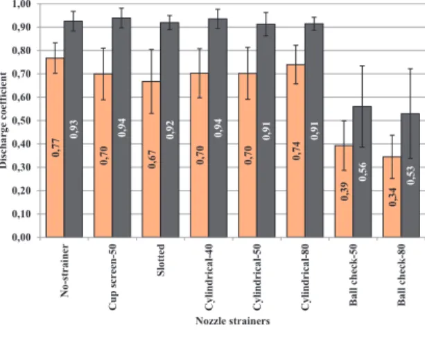
3.4. Evaluation of discharge coefficient (Cd)
Figure 4 shows the mean value of discharge coefficient (Cd) of the multi-range (LU) and anti-drift (AD) nozzles obtained from using together with the strainer types. For the cup screen, slotted, cylindrical strainers and the usage without strainer, the Cd means ranged from 0.67 to 0.77 for the AD nozzle, and 0.91 to 0.94 for the LU nozzle. These results clearly showed that the Cd means of the LU nozzle were found higher than those of the
AD nozzle. The results of the Cd data showed that the ball-check strainers caused the Cd to decrease compared to the other strainer types and the usage without strainer (Figure 4). The Cd means of the nozzles used with the ball-check strainers of 50- and 80- meshes was determined as 0.39 and 0.34 for the AD nozzle, respectively, and 0.56 and 0.53 for the LU nozzle, respectively.
13 The ball-check strainers caused the individual flow rate deviation of the nozzles to increase. The individual flow rate deviation of the nozzles used with the ball-check strainers of 50- and 80-meshes was found as -10.5% and -9.9% for the AD nozzle, respectively, and -12.0% and -12.8% for the LU nozzle, respectively. The cup screen, slotted and cylindrical strainers, and the usage of without strainer caused the individual flow rate deviation to range between -2.9% and -0.1% for the AD nozzle, and -4.4% and -2.8% for the LU nozzle. These intervals were negligible for the AD and LU nozzles.
3.4. Evaluation of discharge coefficient (Cd)
Figure 4 shows the mean value of discharge coefficient (Cd) of the multi-range (LU) and anti-drift (AD) nozzles obtained from using together with the strainer types. For the cup screen, slotted, cylindrical strainers and the usage without strainer, the Cdmeans ranged from 0.67 to 0.77 for the AD nozzle, and 0.91 to 0.94 for the LU nozzle. These results clearly showed that the Cdmeans of the LU nozzle were found higher than those of the AD nozzle. The results of the Cddata showed that the ball-check strainers caused the Cdto decrease compared to the other strainer types and the usage without strainer (Figure 4). The Cdmeans of the nozzles used with the ball-check strainers of 50- and 80- meshes was determined as 0.39 and 0.34 for the AD nozzle, respectively, and 0.56 and 0.53 for the LU nozzle, respectively.
Figure 4- The effect of strainer types on discharge coefficient (Cd) for Anti-drift (AD) and Multi-range (LU) flat-fan nozzles (mean±standard deviation)
Şekil 4- Düşük sürüklenme potansiyelli (AD) ve yüksek etki alanlı (LU) yelpaze hüzmeli memelerin akış katsayısına (Cd) süzgeç tipinin etkisi (ortalama±standart sapma)
In Table 6, the Cdmean values of the AD and LU nozzles used with different types of strainers and orifice sizes were displayed. In general, while the increasing orifice sizes for both nozzle types caused the
Cdmean values to decrease, the Cdmeans increased for both nozzles used with the ball-check strainers.
0, 77 0, 70 0, 67 0,70 0,70 0,74 0, 39 0, 34 0, 93 0,94 0, 92 0,94 0, 91 0,91 0, 56 0, 53 0,00 0,10 0,20 0,30 0,40 0,50 0,60 0,70 0,80 0,90 1,00 N o-s tr ai ne r C up screen -5 0 Sl ot te d C yl in dr ic al -4 0 C yl in dr ic al -5 0 C yl in dr ic al -8 0 Ba ll ch ec k-50 Ba ll ch ec k-80 D isch arg e co ef fici en t Nozzle strainers
Anti-drift (AD) nozzle Multi-range (LU) nozzle
Figure 4- The effect of strainer types on discharge
coefficient (Cd) for Anti-drift (AD) and Multi-range
(LU) flat-fan nozzles (mean±standard deviation)
Şekil 4- Süzgeç tipinin düşük sürüklenme potansiyelli (AD) ve yüksek etki alanlı (LU) yelpaze
hüzmeli memelerin akış katsayısına (Cd) etkisi
(ortalama±standart sapma)
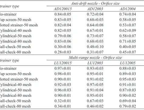
In Table 6, the Cd mean values of the AD and LU nozzles used with different types of strainers and orifice sizes were displayed. In general, while the increasing orifice sizes for both nozzle types caused the Cd mean values to decrease, the Cd means increased for both nozzles used with the ball-check strainers.
The discharge coefficient (Cd) is a significant design parameter revealing the flow characteristic of nozzles. The Cd of a nozzle exit orifice depends on the size of the orifice and nozzle design regarding its geometry (Srivastava et al 1993) and clarify energy loss from eddies and friction through the exit orifice (Womac & Bui 2002).
569
Ta r ı m B i l i m l e r i D e r g i s i – J o u r n a l o f A g r i c u l t u r a l S c i e n c e s 21 (2015) 558-571
Wilkinson et al (1999) has stated that the Cd for spray nozzles varied between 0.15 and 0.65. Sayıncı et al (2013) determined that the discharge coefficient for disc-core type of hollow cone nozzles with different core types ranged from 0.14 to 0.61. Reportedly by Womac & Bui (2002), the Cd value was approximately 0.95±0.02 and typically ranged from 0.60 to 0.80 for orifices with sharp edges (ASME 1961). Zhou et al (1996) presented that the Cd of ten flat-fan nozzles belonging to two manufacturers, those with spray angles between 15° and 110°, ranged from 0.91 to 0.98.
The Cd data determined in this study were compatible with the literature findings. The most important parameters affecting the Cd of the nozzle were found to be the nozzle type, strainer type, and orifice size. The higher Cd mean value of the LU nozzle compared to the AD nozzle proved
that the nozzle design based on its geometry was one of the most important parameter. There were minor differences among the Cd mean values of cup screen, slotted, cylindrical strainers and the usage without strainer. The most important variation between the strainer types was found at ball-check strainers because of the lowest Cd mean values for both nozzle types.
4. Conclusions
Based on the results of this study, the following conclusions could be drawn:
• The orifice coefficient (k) of the multi-range (LU) and anti-drift (AD) flat-fan nozzles, which is the slope of the line referring the relation between the flow rate and spray pressure, used with the ball-check strainers were lower than
Table 6- The variation of the discharge coefficient (Cd) for the anti-drift (AD) and multi-range (LU) flat-fan
nozzles used with different types of the strainers with regard to the nozzle orifice sizes (mean±standard deviation)
Çizelge 6- Meme orifis ölçülerine göre farklı tip süzgeçlerle işletilen düşük sürüklenme potansiyelli (AD) ve
yüksek etki alanlı (LU) yelpaze hüzmeli memeler için akış katsayısının (Cd) değişimi (ortalama±standart sapma)
Strainer type AD120015Anti-drift nozzle - Orifice sizeAD12003 AD12004
No-strainer 0.84±0.05 0.72±0.04 0.74±0.04 Cup screen-50 mesh 0.83±0.05 0.68±0.03 0.58±0.05 Slotted strainer-50 mesh 0.82±0.04 0.64±0.08 0.53±0.07 Cylindrical-40 mesh 0.82±0.05 0.67±0.01 0.62±0.09 Cylindrical-50 mesh 0.79±0.06 0.73±0.07 0.58±0.07 Cylindrical-80 mesh 0.83±0.06 0.68±0.03 0.71±0.05 Ball-check-50 mesh 0.30±0.06 0.48±0.10 0.40±0.05 Ball-check-80 mesh 0.28±0.03 0.31±0.07 0.45±0.07
Strainer type LU120015Multi-range nozzle - Orifice sizeLU12003 LU12005
No-strainer 0.97±0.01 0.93±0.03 0.88±0.03 Cup screen-50 mesh 0.98±0.01 0.95±0.01 0.89±0.03 Slotted strainer-50 mesh 0.90±0.01 0.91±0.02 0.95±0.03 Cylindrical-40 mesh 0.92±0.03 0.97±0.05 0.91±0.01 Cylindrical-50 mesh 0.96±0.03 0.91±0.04 0.87±0.03 Cylindrical-80 mesh 0.90±0.01 0.95±0.01 0.90±0.02 Ball-check-50 mesh 0.32±0.01 0.67±0.03 0.69±0.04 Ball-check-80 mesh 0.34±0.01 0.46±0.02 0.79±0.02