MinIAQ-II: A Miniature Foldable Quadruped with an Improved Leg
Mechanism
Mohammad Askari
*, Cem Karakadıo˘glu
*, Furkan Ayhan, and Onur ¨
Ozcan
Bilkent University, Mechanical Engineering Department, Ankara, Turkey
Abstract— Origami has long been renowned as a simple yet
creative form of art and its folding techniques have recently inspired advances in design and fabrication of miniature robots. In this work, we present the design and fabrication novelties, enhancements, and performance improvements on MinIAQ (Miniature Independently Actuated-legged Quadruped), an origami-inspired, foldable, miniature quadruped robot with individually actuated legs. The resulting robot, MinIAQ-II, has a trajectory-optimized leg actuation mechanism with longer stride, improved traction, less flexure joint bending, and smaller leg lift resulting in faster and smoother walking, better maneu-verability, and higher durability and joint life. In order to max-imize the joint fatigue life while keeping the leg design simple, the initial four-bar mechanism is optimized by manipulating the joint locations and changing the leg link into a non-straight knee shape with a fixed-angle lock. Despite having a 1 cm longer frame to embed its new actuation mechanism, the overall weight and dimensions are similar to its first version as its legs are no longer extended beyond its frame. As a result, MinIAQ-II is 12-cm-long, 6-cm-wide, 4.5-cm-high and weighs 23 grams. The test results demonstrate the improvement in speed over its predecessor from 0.65 to more than 0.8 bodylengths/s at 3 Hz, and an approximate decrease in body’s roll±21◦ to±9◦ and pitch from 0◦–11◦ to 0◦–7◦. The independent actuation and control over each leg enables such a robot to be used for gait studies in miniature scale, as is the next direction in our research.
Index Terms— Origami-Inspired Robots, Foldable Robots,
Miniature Robots, Legged Robots, Mechanism Design, Uncon-ventional Manufacturing.
I. INTRODUCTION
Robots can come in a variety of shapes and sizes, but certain tasks can only be accomplished by a small group of miniature robots. Constraints such as low-cost, rapid and mass fabrication, customizability, and modularity make small scale robots potential candidates for many applications. Their agility, silent operation, and lightweight structures make miniature robots capable of performing tasks such as inspection, surveillance, exploration, and search and rescue missions in inaccessible or hazardous environments [1], [2]. Such robots have also recently become indispensable part of research, education, and swarm studies due to their inexpensive yet rapid prototyping [3], [4]. However, the main challenges in miniature robotics lie in the manufacturing, actuation and control at the small scale.
One of the original solutions in fabrication of small scale robots is the Smart Composite Manufacturing (SCM) method developed in UC Berkeley [5], [6], which has yielded many successful early miniature robots such as DASH [7] and
∗These authors contributed equally to this work.
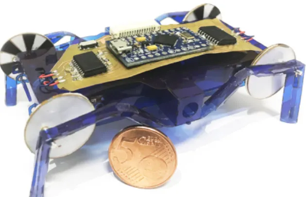
Fig. 1. MinIAQ-II: A foldable miniature quadruped robot with independent leg actuation and improved mechanism design.
family of RoACH robots [8], [9]. In later years, some other fabrication methods are born out of SCM, such as PC-MEMS [10] and pop-up MEMS [1]. At the same time, roboticists have combined these techniques with the knowledge gener-ated from origami and kirigami arts and started the foldable robotics field [11] in which a robot is made out of a single sheet of material by successive folding over a crease pattern. Several interesting foldable robots are reported that can accomplish tasks such as grasping [12], [13], [14], crawling [15], [16], flying [17], and walking [4], [18].
Even though there are several examples of foldable and/or miniature robots, there are very few studies on miniature or microrobot locomotion and gait studies [19]. The main reason is the actuation challenge of these robots. Since most miniature scale actuators do not have absolute encoders, it is very hard to adjust and control gaits at this scale. Therefore, locomotion and gaits are often initially optimized and are locked into the robot using mechanism design such as in [18]. While these robots function perfectly, they cannot change gait and thus cannot be used for gait studies in small scale. Due to this lack of gait studies for miniature robots, we still do not know if modifying gait under certain environmental factors would improve the locomotion.
We have originally designed MinIAQ with individually actuated legs to answer this need [20]. However, the original version is relatively slow, and it cannot maneuver properly due to the easy-to-make leg mechanism which has a poor trajectory. Through designing the first version of our robot, we have gained a lot of experience on mechanism design for foldable robots and we have used this knowledge to create an improved foldable mechanism for higher traction and better stability. The improved mechanism requires links that are not flat, essentially joints that are fixed to a specific angle.
Proceedings of the 2017 IEEE
International Conference on Robotics and Biomimetics December 5-8, 2017, Macau SAR, China
In this paper, we demonstrate these design enhancements, as well as present the new version of our robot. The major contributions of this paper are the enhanced easy-to-fold four-bar leg mechanism design of the new version of MinIAQ as well as a systematic approach to create non-straight rigid foldable links, i.e. link designs with fixed-angle joints in the middle. We believe that the novelties in our design of foldable structures in the original and new version robots can be applied to similar foldable or conventional microrobots and mechanisms. Like its predecessor, the current version of our robot, named MinIAQ-II (see Fig. 1), weighs 23 grams, is 12 cm in length, 6 cm in width, 4.5 cm in height, and can walk forward with a speed of more than 0.8 bodylengths/sec at 3 Hz stride frequency. Having optimized the actuation mechanism trajectory and observed comparable performance improvements of MinIAQ-II, we intend to use this robot to perform gait studies in miniature scale robots.
II. MINIAQ-II DESIGN
A. Rigid Linkages, Flexure Joints and the Body
In MinIAQ-II, 100-micrometer-thick PET sheets, same as the material used in the original MinIAQ [20], are used as the main structural material. To create kinematic chains, the well-known compliant flexure joints and triangular rigid beams are utilized. Most of the kinematic chain uses the conventional foldable robot links and joints. However, this easy-to-make, straight rigid link shape has to be altered into a non-straight link for one of the links in the kinematic chain to improve the trajectory of the mechanism. Details on the kinematic analysis and the non-straight link fabrication are given in sections II-B and II-C.
Due to the nature of foldable robot fabrication that em-ploys a single thin sheet of material as the main structural element, integrity of the main frame and rigid linkages are very important. To achieve a reasonable degree of structural integrity, several types of tab-and-fastener locking mecha-nisms are embedded into the original design. In the original MinIAQ design, we have introduced T-folds to increase bending stiffness of the main frame of the body, U-shaped fastener tabs to keep the folded structures locked, and tight fit tab-and-slot fasteners to block sliding dislocations on structure planes. The T-folds are created as a crease pattern of three parallel lines on the main frame part of the sheet. When the three parallel lines are folded inwards 90 degrees, outwards 180 degrees, and outwards 90 degrees, respectively, they form a T-shaped structure in the body [20]. If T-folds, U-fasteners and tight fit tab-and-slots are used together in right spots, the T-folds become I-beam like structures and the main body frame enclosure becomes very stiff; it does not bend, twist, or buckle during operation. In Fig. 2, the T-folds are shown as green, whereas the U-fasteners are blue and tight fit tab-and-slots are yellow.
Since the actuation is done by four different DC mo-tors and they are controlled with the feedback of four IR reflectance sensors, appropriate housing and placement for these components are done on T-folds. For a single DC motor housing, tight circular openings on two set of parallel T-folds
are made (two pairs of T-folds are used on each side of the main frame), and the IR sensors are placed inside the outer T-folds with a small opening for emitter and receiver. Part of the large gap in between the inner T-folds is used for battery placement that can be seen in Fig. 2. The battery can easily be accessed, removed for charging or replaced using the bottom hatch door shown as purple in Fig. 2. The remaining space can be used for any potential components to be added in the future versions.
Fig. 2. The robot’s main frame showing T-folds (green) with motor and sensor housings, double-sided coupled locking tabs for T-folds (red), U-shaped fasteners (blue), tight fit extension tab-and-slots (yellow), and the bottom hatch door (purple) for battery placement (brown).
B. Locomotion Mechanism Optimization
The original easy-to-fold four-bar leg design in MinIAQ has a relatively poor trajectory, therefore, the robot is quite bouncy and slow [20]. Essentially, a flatter and more ellip-tical trajectory is needed in order to maximize the lateral motion during ground contact and reduce the bounciness. Altering the straight coupler link into a knee-shaped link, as can be observed in many animals, can shift the trajectory of the tip of the leg more in parallel with the ground. But this alteration is not straight-forward due to restrictions of the manufacturing process and 2D unfolded design complexities. Thus, the simplest solution to tackle a non-straight rigid link design is to make a fixed-angle locking joint and incorporate that to the coupler link design.
The kinematic analysis of the mechanism of MinIAQ initiates with the assumption that the planar coordinates of the node A (point attached to the robot’s frame) and node B (motor location) are fixed and the crank angle φ is known, meaning that the unknowns are the coordinates of the nodes C, D and E (Fig. 3). Since the length of the cam shaft encoders (link 2), is known, the exact coordinates for the node D can be determined as:
xD= xB+ l2cos(φ) (1)
yD= yB+ l2sin(φ) (2)
Here,li is the length of theithlink andxi andyi are the planar coordinates of the nodes. The other unknown is the position of the node C,xC andyC , which can be found by making use of the fact that the links 3 and 4 have constant lengths. By writing the lengths l3 and l4 in terms of the planar coordinates of the nodes A and C, the following set of equations can be obtained:
Fig. 3. A schematic of the generalized modified four-bar leg mechanism considered in the design of MinIAQ-II locomotion. The red dashed lines indicate the nodal design constraints and the blue dashed curve represents the ideal goal trajectory used in the optimization algorithm.
(xC− xA)2+ (yC− yA)2= l24 (3)
(xC− xD)2+ (yC− yD)2= l23 (4)
Substituting the lengths and known coordinates, the equa-tions (3) and (4) become two quadratic equaequa-tions with two unknowns, xC and yC. Solving for these unknowns yields two sets of solution for the xC and yC. This ambiguity arises from the fact that the mechanism has two closures and it can be eliminated by imposing a condition on the solutions such that the solution set with higher yC, i.e. open assembly configuration, is preferred over the crossed assembly configuration.
Last unknown coordinates, xE andyE, can be found by considering the fact that the links 3 and 5 are fixed to each other with a constant angle of ψ in between, making them practically one rigid link. Note that, an angle of ψ = 0 essentially gives the kinematics of the original version of MinIAQ. To utilize this fact, the angle of link 3,β needs to be determined as:
β = arctan((yD− yC)/(xD− xC)) (5) The angle of link 5 and consequently coordinates of the point E can be found by:
θ = β − ψ (6)
xE= xD+ l5cos(θ) (7)
yE= yD+ l5sin(θ) (8) The kinematic analysis outlined above provides the basis of the position-based optimization methodology that is em-ployed to determine a set of design parameters for the best achievable trajectory for this specific four-bar leg design. In optimizing the mechanism, certain criteria and design constraints are imposed. The algorithm is to carefully define regions in which each individual node can be relocated incrementally such that the resulting leg trajectory is as close as possible to the ideal trajectory. These constraint regions for nodes as well as the ideal walking trajectory, with straight parallel contact with the ground, are shown with dashed lines
on Fig. 3. It should also be noted that even though there are many straight-line linkages known, most of them require several of the joints making full (or close to full) rotations. Such joints cannot be fabricated using foldable techniques, hence the optimization outlined in this section is conducted. Selection of the constraint regions are not done arbitrarily to avoid unnecessary customization of the original robot’s crease pattern. The coordinates of the motor, i.e. node B, is fixed at its location. Node A, which connects to the robot’s main frame is restricted to be shifted only along x-direction and away from the other links, at most by a few millimeters. This constraint on xA allows a less stressed flexure joint bending (smaller maximum bending angle between links 3 and 4) which has been the primary cause of robot’s failure due to fatigue. Similarly, the constraint region for node C, which correlates with the link lengthsl3 andl4, is selected relatively wider along horizontal direction to eliminate pos-sible undesired solutions with highly bent flexure joints. The constraint on node D is defined as a relatively small region to ensure that the length of the crank, i.e. encoders, are neither too small nor too big. Lastly, a large region is defined for the coordinates of the tip of the leg, node E, which in other words correspond to different coordinates by varying fixed-angle ψ lock and leg link l5. Thus, the design parameters for optimization algorithm are xA, xC, yC, l2, l5, and ψ. The optimization algorithm seeks for the best set of design variables that minimizes the cost function, being the least square error between the resulting tip trajectory and the ideal desired trajectory. Fig. 4 illustrates the trajectories of the final configuration of the optimized mechanism as well as the trajectory of the original MinIAQ’s mechanism. With the resulting mechanism, MinIAQ-II benefits from a longer stride length, improved lateral ground contact, smaller leg lift (bounciness), and less flexure joint bending.
(a) (b)
Fig. 4. (a) Original locomotion mechanism trajectory of MinIAQ. (b) Optimized mechanism trajectory of MinIAQ-II.
C. Fixed-Angle Knee Joint Design
The implementation of the enhanced mechanism requires an unfolded crease pattern to precisely obtain a required fixed angle lock between two triangular rigid beams. There are examples of non-straight members such as in gripping structure of [14] in literature. However, to the best of our knowledge, no detail is given on how to systemically design and control the locking angle of such rigid bent links, therefore implementing similar designs for other researchers are very hard. For this reason, many design iterations are done to get a rigid-enough locking mechanism at any desired design angle specified. The majority of the changes in
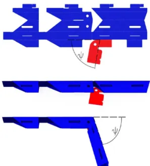
MinIAQ-II design, compared to the original MinIAQ, comes from its optimized leg mechanism shown in Fig. 5. The figure illustrates how a single leg is folded in two main steps to form the final shape. The proposed design for the knee-shaped link consists of two regular triangular beams connected with a short flexure joint and an inclined fixed-angle tab-and-fastener locking mechanism next to it. Note that the angle between the inclined fastener and the leg orientation on the unfolded structure is equal to the resulting desired fixed-angle lock between the folded beams. With the proposed design, any two triangular beams can potentially be locked together at any desired acute or obtuse angles. If one requires to lock the right portion of the leg with a downwards orientation, similar to MinIAQ-II, the triangular beams can be folded in the reverse direction and the locking mechanism can be placed accordingly to be folded and locked in reverse. In the original MinIAQ, the triangular beams have been folded upwards, but they are folded downwards in MinIAQ-II to enable the 81◦ fixed-angle lock.
Fig. 5. A schematic representation of the unfolded to folded structure of the new leg design. The knee shaped triangular beam link consists of two triangular beams and a fixed angle joint that is locked in place with the help of the inclined fastener.
D. Actuation, Electronics and Power
With the intention of independent actuation of each leg, MinIAQ is designed with four very small and lightweight (approx. 1.25 grams each) motors (Pololu, Sub-Micro Plastic Planetary Gearmotor). The major drawback of using these motors is the lack of any type of built-in encoders. For this reason, it is necessary to design a feedback controller for each motor to properly adjust the speed and position of each leg. Therefore, small IR sensors are selected to house next to the motors and custom cam encoders with black and white stripes are made and attached to the motors.
The IR sensors need three connections (power, ground and signal) to operate in order to provide feedback signal to the controller. To avoid complex wiring and soldering of each sensor, a flexible PCB that will be located inside the
body frame is designed, which can be cut into shape and extended to the sensors. This inner flexible board powers every sensor and transfers the signals to the controller (see Fig. 6(a)). A copper clad polyimide flexible sheet is chosen as the PCB material (Dupont, Pyralux). The inner flexible PCB interconnects the two sensor couples by two 90 degree folds (Fig. 6-1). Signal and power traces of the inner PCB are combined and bundled in a foldable extension that comes out of the top frame, to be connected to the main controller PCB, which is located on top of the robot, through a socket (Fig. 6-2).
To run the robot, a single cell 3.7 V, 150 mAh LiPo battery is used and its voltage is boosted to 5 V with a step-up regulator located on the inner flexible PCB (Fig. 6-3)) to power the sensors, the motor drivers, and the microcontroller. The battery is placed between the inner T-folds and is connected to the inner flexible PCB with a socket for easy removal through the hatch door underneath the main frame (see Fig. 2).
The Arduino Pro Micro microcontroller (Fig. 6-4) is placed on the main controller PCB located on top of the main frame, along with two L293DD motor driver ICs (Fig. 6-5), 16 SMT capacitors, on-off slider switch (Fig. 6-6) and an FFC/FPC socket (Fig. 6-2) to connect the inner flexible PCB to the main controller PCB. The main controller PCB can be seen in Fig. 6(b). The inner flexible PCB distributes the regulated 5 V power to the sensors and the main controller PCB and also transfers the signals generated by the sensors.
(a) (b)
Fig. 6. CadSoft Eagle drawing of the PCBs used in MinIAQ-II: (a) Inner flexible PCB for sensor connections and power regulation and distribution. (b) Main controller PCB for controls and driving the actuators. Red color lines show traces on top layer. There are additional ground and power connections that exist on the bottom layer of the PCBs, which are not shown to improve the legibility. The labeled numbers indicate the soldering position of components and connectors described in text.
III. FABRICATION ANDASSEMBLY
Before starting the assembly process of the robot, boards introduced in section II-D must be fabricated and compo-nents must be soldered. The PCBs are manufactured by
coating a mask material on the flexible sheets, ablating the coating with a laser engraver (Universal Laser Systems, VLS 6.60) in raster-scan mode to generate the appropriate mask, and etching the copper at the unmasked locations. Since the board material used is a thin flexible sheet, it must be flattened perfectly and bonded to a flat surface to prevent any wrinkles during ablation process. Before coating the mask material, the surface is cleaned from dust and oils. After initial cleaning, the surface is coated by using a dark, varnish-based paint. Afterwards, the mask material is ablated with a laser engraver to form a positive mask. Unmasked copper regions are then etched using HCl3solvent and the PCB traces remain with mask material on them. The remaining mask material is cleaned with acetone and finally components are soldered to the boards using solder paste and a heat gun. The whole process takes about 4 to 5 hours due to the slow speed of laser raster, relative complexity of the circuits, and the number of components that needs to be soldered.
After the electronics are ready, the robot’s body is fab-ricated and assembled. The PET sheets are cut in the same laser engraver used in manufacturing of the PCBs. The crease pattern used in MinIAQ-II is very similar to the one used originally in MinIAQ. The major design differences are the 10-mm-elongation of the main frame, the change of link lengths of the optimized mechanism (as explained in section II-B), and the fixed angle knee joints (as explained in section II-C). The assembly stage consists of consecutively folding and fastening the T-folds, placing electronics and motors inside, closing and fastening the sides and the top cover, and folding the legs, which is very similar to the initial version of the robot. The difference between MinIAQ-II’s and the original MinIAQ’s assembly processes is the fixed angle knee joint and how it is folded. The assembly time of the robot is about two hours, fairly similar to its predecessor. The folded structure of MinIAQ-II is approximately 6 cm wide, maximum of 4.5 cm high, and 12 cm long. The untethered version weighs 23 grams in total, 3.5 grams of which is the body weight, 5 g is its motors, 5 g is its battery, and the other 9.5 grams comes from its boards, electronic components, encoders, and pins.
IV. OPERATION ANDCONTROL OFMINIAQ-II
A. Control Problem
Inspired by the gait analysis of quadruped animals, we expect trot gait to be ideal for MinIAQ’s general forward locomotion. Trot gait resembles a form of locomotion in which adjacent legs are moved out of phase (180◦) with respect to each other resulting in a relatively stable and one-at-a-time step-wise motion. In the actual tests, the leg synchronization and gait control is observed to be crucial for proper walking motion. Therefore, regarding the control problem, not only the speeds of individual legs have to be matched, but also the phases of the leg motion have to be controlled so that the robot can time its steps.
Due to the lack of encoders on our actuators, a custom absolute encoder is designed to be used in pack with analog
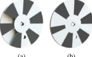
IR reflectance sensors. These custom encoders are utilized to characterize the motors and output a signal providing information to estimate both speed and position of each leg during locomotion. The output values of reflectance sensors are highly dependent on both distance and field of view of the optical emitter and receiver. In the original MinIAQ, we take advantage of the distance sensitivity and use 3D cam shafts (Fig. 7(a)) by which the black stripe in the back layer generates a relatively lower peak voltage than the other front stripes. This smaller peak serves as a reference to identify the actual leg position over one period. A control algorithm has been developed based on such signal and successfully utilized in trot gait synchronization [20]. However, the 3D cam shafts are prone to issues related to the high sensitivity of sensor-cam distance such that a little shift in cams location with respect to the sensor can result in complete disappearance of the small reference peak.
In order to increase control robustness, the encoder design is modified to give a more reliable signal of same form so that we can use the original control algorithm with minimal modifications. The new cam design incorporates a single thinner black stripe (Fig. 7(b)) that benefits from the IR reflectance field of view and generates relatively the same signal with a lower reference peak.
(a) (b)
Fig. 7. (a) 3D cam shaft encoder. (b) Cam shaft encoder with a single thin band.
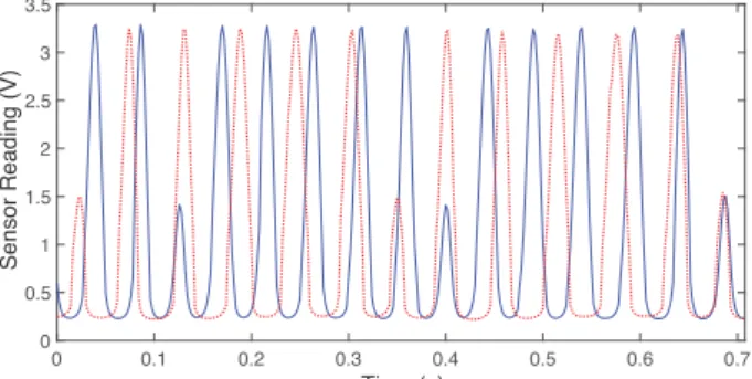
The signal from each motor is used to estimate both the frequency of rotation (based on two consecutive peaks) and relative position of each leg (with respect to the smaller reference peak). Fig. 8 shows the block diagram of the implemented control algorithm. It consists of two interre-lated PD control loops which are fed with the information extracted from the IR sensor signals. The frequency control serves primarily to adjust the speed of all motors to a relatively similar frequency and the position control loop synchronizes the relative phase between the signals with respect to each other. Note that the encoders also serve as the crank links of the actuation mechanism, and to achieve proper trot gait with 180◦ phase difference between legs, we place the corresponding crank pin locations with 180◦ offset on each pair of adjacent encoders. Fig. 9 illustrates the relative synchronization between two motor signals where the frequencies are adjusted and they are brought into same phase, corresponding to a 180◦ phase offset on actual legs.
B. Performance of MinIAQ-II
MinIAQ-II’s performance on straight walking and turning are tested in several experiments and the new version’s per-formance is compared to its predecessor. MinIAQ-II can run about 30 minutes on a single fully charged 150mAh battery and the flexure joints last a few hours of constant operation
Fig. 8. MinIAQ’s closed loop control algorithm block diagram. 0 0.1 0.2 0.3 0.4 0.5 0.6 0.7 Time (s) 0 0.5 1 1.5 2 2.5 3 3.5 Sensor Reading (V)
Fig. 9. Synchronization of two motor signals with respect to each other with 0 phase difference, corresponding to a 180◦ phase offset on actual legs.
before fatigue failure. The kinematic simulation of an ideal trot gait driven at 3 Hz (Fig. 10) is done in SolidWorks for both versions of the robot with correct physical and material properties. While the robot has shown successful performance at different stride frequencies, it is generally run at 3 Hz for tests and simulations because MinIAQ-II achieves a more natural and stable quadrupedalism behavior at 3 Hz stride frequency. The simulation results show the new version’s superiority over the original MinIAQ. The results not only imply larger stride length, but also suggest a more stable walk due to smaller leg lift. Several experiments are conducted to verify the performance increase suggested by the simulations. The experiments demonstrate an increase in average forward locomotion speed from 0.65 bodylengths/s (7.5 cm/s) in original MinIAQ to more than 0.8 bodylengths/s (9.7 cm/s) in MinIAQ-II.
Fig. 10. Comparison between forward leg trajectory for ideal trot gait simulation of MinIAQ-II (top) and MinIAQ (bottom).
Figure 11 shows the simulation results of pitch and roll angle variations at 3 Hz-drive, together with snapshots of experimental results for maximum pitch and roll. The experi-ments are in good agreement with the simulation results. Due to the improved mechanism, MinIAQ-II has a more stable walk and much better maneuverability due to an approximate decrease in body’s roll from±21◦to±9◦and a lower pitch
Fig. 11. Estimation of pitch and roll angles variations from simulation at 3 Hz for both versions of MinIAQ. The snapshots on the right show the maximum recorded pitch and roll from actual tests.
angle of 0◦-7◦ compared to the original MinIAQ’s 0◦-11◦ pitch.
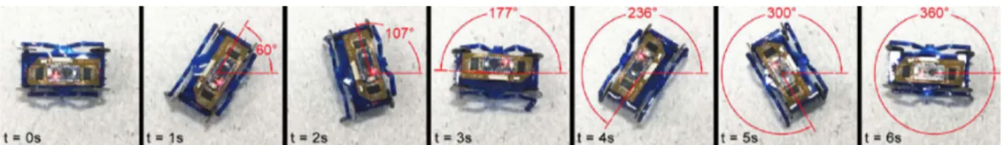
The relatively better stabilization and balance in locomo-tion of MinIAQ-II helps the robot to have a more uniform load distribution on its feet. This uniform load distribution results in improved maneuverability of MinIAQ-II, where its predecessor lacks the most. The feet of the previous version of the MinIAQ cannot keep traction properly due to the varied load distribution and results with an in-place turning with an inconsistent angular speed and low success rate. On the other hand, MinIAQ-II can successfully turn in-place in every trial with an almost constant angular speed. Fig. 12 shows the capability of the robot to turn in-place with a speed of 60◦/s at 3 Hz motor frequency.
V. CONCLUSION ANDFUTUREWORK
In this paper, we present the design and operation of MinIAQ-II, the 2nd generation of our origami-inspired fold-able miniature quadruped with individually actuated legs and an improved locomotion mechanism. The robot is fabricated out of a single PET sheet, weighing only 23 grams. The performance of original MinIAQ suffers from the poor trajectory of its relatively easy-to-make mechanism. The leg mechanism of MinIAQ-II is optimized to achieve a flatter and more elliptical trajectory with larger stride length to improve the traction and the speed, less flexure joint bending to increase joint’s fatigue life, and smaller leg lift to reduce the frame’s bounciness. The new leg design resembles a knee-shaped link which incorporates a novel fixed-angle locking mechanism to obtain non-straight rigid hollow triangular foldable links. The control algorithm performance is also improved by modifying the custom camshaft encoders to generate a more robust signal. The resulting robot benefits from a much smoother walking, better maneuverability, and longer joint life compared to its predecessor. In comparison with the first version robot, MinIAQ-II runs at more than 2 cm/s higher speed with an estimated rate of 0.8 bodylengths/s at 3 Hz motor frequency. It is also capable of performing more reliable in-place turns with 60◦/s angular speed. The maximum roll angle of the robot is more than halved from 21◦ to 9◦ and pitch angles improved from 11◦ to 7◦.
Fig. 12. Snapshots of MinIAQ-II’s improved maneuverability during a zero-radius in-position turning test at 3 Hz drive frequency.
There are several studies that will be done following this work. Even though the design enhancements has served well in improving the overall performance, the leg slip still re-mains a problem. To improve the traction and ground contact, foldable footpads are to be sought and implemented into the leg design. The robot also suffers mainly from fatigue failure at the flexure joints. A fatigue study on foldable flexure joints can play an important role on characterizing their behavior to maximize robot’s lifespan. Last but not least, one of the primary reasons of having individual leg actuation in MinIAQ is to have full control on robot’s gait, which will enable us to perform a thorough gait study on miniature scale robots in recent future.
ACKNOWLEDGMENTS
The authors would like to thank members of Bilkent Miniature Robotics Laboratory for their invaluable assistance throughout this project. This work is funded by the Scientific and Technological Research Council of Turkey (T ¨UB˙ITAK) grant no. 115C107.
REFERENCES
[1] A. T. Baisch, O. Ozcan, B. Goldberg, D. Ithier, and R. J. Wood, “High speed locomotion for a quadrupedal microrobot,” The International
Journal of Robotics Research, vol. 33, no. 8, pp. 1063–1082, 2014.
[2] O. Ozcan, A. T. Baisch, D. Ithier, and R. J. Wood, “Powertrain selection for a biologically-inspired miniature quadruped robot,” in
2014 IEEE International Conference on Robotics and Automation (ICRA). IEEE, 2014, pp. 2398–2405.
[3] A. M. Mehta and D. Rus, “An end-to-end system for designing mechanical structures for print-and-fold robots,” in 2014 IEEE
In-ternational Conference on Robotics and Automation (ICRA). IEEE, 2014, pp. 1460–1465.
[4] S. T. Kalat, S. G. Faal, U. Celik, and C. D. Onal, “Tribot: A minimally-actuated accessible holonomic hexapedal locomotion platform,” in
Intelligent Robots and Systems (IROS), 2015 IEEE/RSJ International Conference on. IEEE, 2015, pp. 6292–6297.
[5] E. Shimada, J. Thompson, J. Yan, R. Wood, and R. Fearing, “Proto-typing millirobots using dextrous microassembly and folding,” Proc.
ASME IMECE/DSCD, vol. 69, no. 2, pp. 933–940, 2000.
[6] R. Wood, S. Avadhanula, R. Sahai, E. Steltz, and R. Fearing, “Micro-robot design using fiber reinforced composites,” Journal of Mechanical
Design, vol. 130, no. 5, p. 052304, 2008.
[7] P. Birkmeyer, K. Peterson, and R. S. Fearing, “Dash: A dynamic 16g hexapedal robot,” in Intelligent Robots and Systems, 2009. IROS 2009.
IEEE/RSJ International Conference on. IEEE, 2009, pp. 2683–2689.
[8] A. M. Hoover, E. Steltz, and R. S. Fearing, “Roach: An autonomous 2.4 g crawling hexapod robot,” in Intelligent Robots and Systems,
2008. IROS 2008. IEEE/RSJ International Conference on. IEEE, 2008, pp. 26–33.
[9] A. O. Pullin, N. J. Kohut, D. Zarrouk, and R. S. Fearing, “Dynamic turning of 13 cm robot comparing tail and differential drive,” in
Robotics and Automation (ICRA), 2012 IEEE International Conference on. IEEE, 2012, pp. 5086–5093.
[10] K. L. Hoffman and R. J. Wood, “Myriapod-like ambulation of a segmented microrobot,” Autonomous Robots, vol. 31, no. 1, p. 103, 2011.
[11] C. D. Onal, R. J. Wood, and D. Rus, “Towards printable robotics: Origami-inspired planar fabrication of three-dimensional mecha-nisms,” in Robotics and Automation (ICRA), 2011 IEEE International
Conference on. IEEE, 2011, pp. 4608–4613.
[12] M. Salerno, K. Zhang, A. Menciassi, and J. S. Dai, “A novel 4-dof origami grasper with an sma-actuation system for minimally invasive surgery,” IEEE Transactions on Robotics, 2016.
[13] E. Vander Hoff, D. Jeong, and K. Lee, “Origamibot-i: A thread-actuated origami robot for manipulation and locomotion,” in 2014
IEEE/RSJ International Conference on Intelligent Robots and Systems.
IEEE, 2014, pp. 1421–1426.
[14] C. D. Onal, M. T. Tolley, R. J. Wood, and D. Rus, “Origami-inspired printed robots,” IEEE/ASME Transactions on Mechatronics, vol. 20, no. 5, pp. 2214–2221, 2015.
[15] C. D. Onal, R. J. Wood, and D. Rus, “An origami-inspired approach to worm robots,” IEEE/ASME Transactions on Mechatronics, vol. 18, no. 2, pp. 430–438, 2013.
[16] K. Zhang, C. Qiu, and J. S. Dai, “Helical kirigami-enabled centimeter-scale worm robot with shape-memory-alloy linear actuators,” Journal
of Mechanisms and Robotics, vol. 7, no. 2, p. 021014, 2015.
[17] Y. Mulgaonkar, B. Araki, J.-s. Koh, L. Guerrero-Bonilla, D. M. Aukes, A. Makineni, M. T. Tolley, D. Rus, R. J. Wood, and V. Kumar, “The flying monkey: A mesoscale robot that can run, fly, and grasp,” in 2016
IEEE International Conference on Robotics and Automation (ICRA).
IEEE, 2016, pp. 4672–4679.
[18] M. Agheli, S. G. Faal, F. Chen, H. Gong, and C. D. Onal, “Design and fabrication of a foldable hexapod robot towards experimental swarm applications,” in 2014 IEEE International Conference on Robotics and
Automation (ICRA). IEEE, 2014, pp. 2971–2976.
[19] R. S. Pierre and S. Bergbreiter, “Gait exploration of sub-2 g robots using magnetic actuation,” IEEE Robotics and Automation Letters, vol. 2, no. 1, pp. 34–40, Jan 2017.
[20] C. Karakadioglu, M. Askari, and O. Ozcan, “Design and operation of miniaq: An untethered foldable miniature quadruped with individually actuated legs,” in 2017 IEEE International Conference on Advanced