Multipath Fading Effect on Terrestrial Microwave
LOS Radio Links
Polat Goktas1, Satilmis Topcu2, Ezhan Karasan1 and Ayhan Altintas1,2 1Department of Electrical - Electronics Engineering, Bilkent University
Ankara, TR-06800, Turkey {pgoktas, ezhan, altintas}@ee.bilkent.edu.tr
2Bilkent University, Communications and Spectrum Management Research Center (ISYAM)
Ankara, TR-06800, Turkey [email protected]
Abstract—In this paper, the calculation of both the total re-ceived power with the effect of the ground reflection and the fade margin to find out the link availability for terrestrial microwave LOS (line-of-sight) radio links is proposed. The expressions are derived from clear-air, rainfall propagation mechanisms and multipath fading due to multipath arising from surface reflection along the defined microwave LOS radio link. We verify the mathematical model by using the ATDI ICS telecom software over sample microwave LOS radio links located in Turkey.
I. INTRODUCTION
The quality of point-to-point microwave LOS/NLOS ra-dio link communication is expressed by the received power. In the literature, prediction models for deep-fading range of the multipath fading distribution have been in exis-tence for several years. The best known techniques are Morita [1] for Japan, Barnett-Vigants [2], [3] for the United States and Rec. ITU-R P. 530 [4] in the worldwide. In accordance with Olsen-Tjelta [5] paper, the application of three methods for many regions around the world clearly shows that the ITU-R model [4] gives the best overall per-formance in modelling flat-fading statistics on overland links and also on links in rugged inland regions. In this study, the multipath fading outage prediction method proposed by Rec. ITU-R P. 530 model [4] is studied. Rec. ITU-R P. 530 multipath fading prediction model [4] is composed of four significant clear-air and rainfall propagation mechanisms on terrestrial microwave LOS/NLOS radio links: attenuation due to atmospheric gases and rain, fading due to the multipath effects like diffuse reflections among the defined path profile and diffraction losses over terrain obstructions.
This paper is divided into two parts. The first part figures out the calculation process of the total received power with the effect of the diffuse reflection points among the path profile and analyses link unavailability as a function of fade margin. The second part compares the overall performance in terms of the received power over some microwave LOS radio links with ATDI ICS telecom software platform [6]. Due to space limitation and to reduce the number of figures, we will present only one sample case study which illustrated results of both the proposed method and other model via ATDI ICS telecom software platform [6].
II. THEORY OFGROUNDREFLECTIONLINKBUDGET AND FADEMARGINEVALUATION
Rec. ITU-R P. 530 model [4] provides a procedure of esti-mating the path losses for clear-air and precipitation conditions and outage probability on the terrestrial microwave radio links, but the available signal power formulation at the receiver with the effect of the diffuse reflection coefficient is not defined in the multipath fading prediction model. We also enhance the fade margin calculation according to the calculated received power in order to find the exact link availability value.
A free space loss, LF SL (dB), is calculated using the Friis
transmission loss formula expressed as [4]
LF SL= 92.45 + 20log(d) + 20log(f ) (1)
where d is the distance between the Tx (transmitter) and Rx (receiver) antennas in km and f is the frequency in GHz.
The available signal power at the receiver site according to direct signal without ground reflection effect formulated as
Pr = Ptx+Gtx+Grx−CL−(LF SL+Ag+Ar+Adif f) (2)
whereby, Ptxis the transmitted power in dBm, Gtx and Grx
are the gain of the Tx and Rx antennas in dB, CL is the cable loss in dB, Ag and Ar are attenuation due to atmospheric
gases and rain in dB, and Adif f is the diffraction loss over
the terrain profile in dB.
The total received power with the effect of the ground reflection in dBm is given by Ptotal= 10 log(10 Pr 10 × (1 − 10 −min(Ls) 20 )) (3)
where Ls are the reflection losses of all reflection point
candidates among the path profile in dB. The fade margin calculation is also given by
A = Ptotal− PN− SN R (4)
where PN is the noise power in dBm and SNR is target
signal-to-noise ratio in dB.
For the unavailability due to multipath, the average worst month value, pw, is calculated as a function of the calculated
fade margin, terrain roughness, geoclimatic factor, path length and frequency parameters described in Rec. ITU-R P. 530 [4].
918
Moreover, the worldwide terrain roughness data provided by ITU-R is too coarse so that we change the resolution of terrain roughness data and investigate its effect on the link availability [7].
III. SIMULATIONRESULTS
To verify the proposed method in the microwave per-formance analysis, we applied simulations on terrestrial microwave LOS radio links located in Ankara, Turkey. A path profile between transmitter and receiver sites generated using a Digital Terrain Elevation Data (DTED 1) that has a post spacing with 3-arc seconds (approximately 100 meters). Some main parameters used for simulation are summarized in Table I. The terrain path profile of the terrestrial microwave LOS radio link is presented in Fig. 1. The obtained results are also summarized in Table II and III.
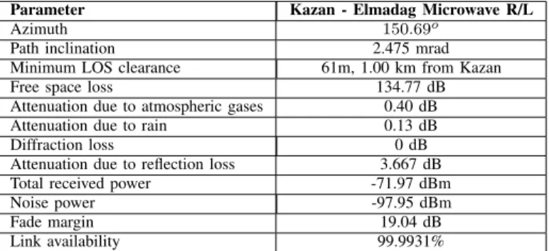
The analysis of overall performance in terms of the total received power over sample microwave LOS radio link shows that the proposed method is compatible with the other model via ATDI ICS telecom software platform [6].
TABLE I
TERRESTRIAL LINK PARAMETERS FORKAZAN- ELMADAG MICROWAVE
LOSRADIO LINK
Parameter Kazan - Elmadag Microwave R/L
Transmitter station, Kazan 40
oN 18037.60”
32oE 360 43.00”
Receiver station, Elmadag 39
oN 4803.30”
32oE 590 2.00”
Altitude of transmitter station (a.s.l) 1665 m Altitude of receiver station (a.s.l) 1825 m
Antenna height (a.g.l) 15 m
Radio frequency 2 GHz
Transmitted power 25 dBm
Transmitter/Receiver antenna gain 22 dBi
HPBW 8o
Cablo losses 2×1 dB
Target SNR 6.95 dB
Bandwith 40 MHz
Diffraction method Delta-Bullington
Time percentage for rain attenuation 0.01%
Polarization type Vertical
Ground type Medium Dry Ground
Season type Winter
TABLE II
LINK STUDY SIMULATION RESULTS ONKAZAN- ELMADAG TERRESTRIAL MICROWAVELOSRADIO LINK
Parameter Kazan - Elmadag Microwave R/L
Azimuth 150.69o
Path inclination 2.475 mrad
Minimum LOS clearance 61m, 1.00 km from Kazan
Free space loss 134.77 dB
Attenuation due to atmospheric gases 0.40 dB
Attenuation due to rain 0.13 dB
Diffraction loss 0 dB
Attenuation due to reflection loss 3.667 dB
Total received power -71.97 dBm
Noise power -97.95 dBm
Fade margin 19.04 dB
Link availability 99.9931%
TABLE III
RESULTS OFATDI ICSTELECOM SOFTWARE ONKAZAN- ELMADAG TERRESTRIAL MICROWAVELOSRADIO LINK
Parameter Kazan - Elmadag Microwave R/L
Free space loss 135 dB
Attenuation due to atmospheric gases 0.40 dB Attenuation due to rain (27.66 mm/h) 0.20 dB
Diffraction loss 0 dB
Attenuation due to reflection loss 3.0 dB
Total received power -71.24 dBm
Fig. 1. Kazan - Elmadag microwave LOS radio link profile over terrain with the terrain elevations in above sea level adjusted for 4/3 effective Earth radius curvature. (The blue and the red curve indicate the First Fresnel zone and the 0.6 First Fresnel zone, respectively.)
IV. CONCLUSIONS
In this paper, the performance analysis in terms of both total received power and link availability of terrestrial microwave LOS radio link have been simulated and evaluated. The effect of the ground reflection is investigated on the worst month link availability of the microwave LOS radio link. The link analysis for the proposed method is approved by using the ATDI ICS telecom software platform [6]. The ongoing work will be focused on field measurements which will be used for better comparison of the results of the proposed method.
REFERENCES
[1] K. Morita, “Prediction of Rayleigh fading occurrence probability of line-of-sight microwave links”, Rev. Elec. Commun. Lab., vol. 18, pp. 810– 821, December 1970.
[2] W. T. Barnett, “Multipath propagation at 4, 6 and 11 GHz”, Bell Syst. Tech. J., vol. 51, pp. 311–361, February 1972.
[3] A. Vigants, “Space diversity engineering”, Bell Syst. Tech. J., vol. 54, pp. 103–142, January 1975.
[4] International Telecommunication Union, “Propagation data and prediction methods required for the design of terrestrial line-of-sight systems,” Recommendation ITU-R P. 530-15, 2013.
[5] R. L. Olsen and T. Tjelta, “Worldwide techniques for predicting the multipath fading distribution on terrestrial LOS links: Comparison with regional techniques”, IEEE Trans. Antennas Propag., vol. 51, pp. 23–30, January 2003.
[6] http://www.atdi.com/ics-telecom/
[7] P. Goktas, A. Altintas, S. Topcu and E. Karasan, “The effect of terrain roughness in the microwave line-of-sight multipath fading estimation based on Rec. ITU-R P. 530-15”, General Assembly and Scientific Symposium (URSI GASS), 2014 XXXIth URSI, August 2014.