Optimization and tunability of deep
subwavelength resonators for metamaterial
applications: complete enhanced transmission
through a subwavelength aperture
Kamil Boratay Alici,1, 2* Filiberto Bilotti,3 Lucio Vegni,3 and Ekmel Ozbay1, 2, 41Nanotechnology Research Center, Bilkent University, Bilkent, 06800 Ankara, Turkey. 2Department of Physics, Bilkent University, Bilkent, 06800 Ankara, Turkey 3
Department of Applied Electronics, University of Roma Tre Via della Vasca Navale, 84-00146, Rome, Italy. 4Department of Electrical and Electronics Engineering, Bilkent University, Bilkent, 06800 Ankara, Turkey
*Corresponding author: [email protected]
Abstract: In the present work, we studied particle candidates for
metamaterial applications, especially in terms of their electrical size and resonance strength. The analyzed particles can be easily produced via planar fabrication techniques. The electrical size of multi-split ring resonators, spiral resonators, and multi-spiral resonators are reported as a function of the particle side length and substrate permittivity. The study is continued by demonstrating the scalability of the particles to higher frequencies and the proposition of the optimized particle for antenna, absorber, and superlens applications: a multi-spiral resonator with λ/30 electrical size operating at 0.810 GHz. We explain a method for tuning the resonance frequency of the multi-split structures. Finally, we demonstrate that by inserting deep subwavelength resonators into periodically arranged subwavelength apertures, complete transmission enhancement can be obtained at the magnetic resonance frequency.
© 2009 Optical Society of America
OCIS Codes: (160.3918) Materials: Metamaterials; (260.5740) Physical optics: Resonance. (260.2065) Physical optics: Effective medium theory.
References and links
1. R. A. Shelby, D. R. Smith, and S. Schultz, “Experimental verification of a negative index of refraction,” Science 292, 77-79 (2001).
2. J. B. Pendry, A. J. Holden, W. J. Stewart, and I. Youngs, “Extremely low frequency plasmons in metallic mesostructures,” Phys. Rev. Lett. 76, 4773-4776 (1996).
3. J. B. Pendry, A. J. Holden, D. J. Robbins, and W. J. Stewart, “Magnetism from conductors and enhanced nonlinear phenomena,” IEEE Trans. Microwave Theory Tech. 47, 2075-2084 (1999).
4. K. B. Alici and E. Ozbay, “Characterization and tilted response of a fishnet metamaterial operating at 100 GHz,” J. Phys. D: Appl. Phys. 41, 135011.
5. M. Gokkavas, K. Guven, I. Bulu, K. Aydin, R. S. Penciu, M. Kafesaki, C. M. Soukoulis, and E. Ozbay, “Experimental demonstration of a left-handed metamaterial operating at 100 GHz,” Phys. Rev. B 73, 193103 (2006).
6. B. D. F. Casse, M. O. Moser, J. W. Lee, M. Bahou, S. Inglis, and L. K. Jian, “Towards three-dimensional and multilayer rod-split-ring metamaterial structures by means of deep x-ray lithography,” Appl. Phys. Lett. 90, 254106 (2007).
7. S. Zhang, W. Fan, K. J. Malloy, S. R. J. Brueck N. C. Panoiu, and R. M. Osgood, “Near-infrared double negative metamaterials,” Opt. Express 13, 4922-4930 (2005).
8. K. Buell, H. Mosallaei, and K. Sarabandi, “A substrate for small patch antennas providing tunable miniaturization factors,” IEEE Trans. Microwave Theory Tech. 54, 135-146 (2006).
9. Alu, F. Bilotti, N. Engheta, and L. Vegni, “Subwavelength compact resonant patch antennas loaded with metamaterials,” IEEE Trans. Antennas Propag. 55, 13-25 (2007).
10. K. B. Alici and E. Ozbay, “Electrically small split ring resonator antennas,” J. Appl. Phys. 101, 083104 (2007).
11. K. B. Alici and E. Ozbay, “Radiation properties of a split ring resonator and monopole composite ,” Physica Solidi Status B 244, 1192-1196 (2007).
12. Erentok and R. Ziolkowski, “A hybrid optimization method to analyze metamaterial-based electrically small antennas,” IEEE Trans. Antennas Propag. 55, 731-741 (2007).
13. Alu, F. Bilotti, N. Engheta, and L. Vegni, “Metamaterial covers over a small aperture,” IEEE Trans. Antennas Propag. 54, 1632-1643 (2006).
14. D. Sievenpiper, L.Zhang, R. F. J. Broas, N. G. Alexopolous, and E. Yablonovitch, “High-impedance electromagnetic surfaces with a forbidden frequency band,” IEEE Trans. Microwave Theory Tech. 47, 2059-2074 (1999).
15. Ourir, A. Lustrac, and J. M. Lourtioz, “All-metamaterial-based subwavelength cavities (λ/60) for ultrathin directive antennas,” Appl. Phys. Lett. 88, 084103 (2006).
16. J. Garcia-Garcia, F. Martin, F. Falcone, J. Bonache, J. d. Baena, I. Gil, E. Amat, T. Lopetegi, M. A. G. Laso, J. A. M. Iturmendi, M. Sorolla, and R. Marques, “Microwave filters with improved stopband based on sub-wavelentgh resonators,” IEEE Trans. Microwave Theory Tech. 53, 1997-2006 (2005).
17. J. Bonache, I. Gil, J. Garcia-Garcia, and F. Martin, “Novel microstrip bandpass filters based on complementary split-ring resonators,” IEEE Trans. Microwave Theory Tech. 18, 265-271 (2006). 18. F. Falcone, F. Martin, J. Bonache, M. A. G. Laso, J. Garcia-Garcia, J. D. Baena, R. Marques, and M.
Sorolla, “Stop-band and band-pass characteristics in coplanar waveguides coupled to spiral resonators,” Microw. Opt. Techn. Lett. 42, 386-388 (2004).
19. G. Parazzoli, R. B. Greegor, K. Li, B. E. C. Koltenbah, and M. Tanielian, “Experimental Verification and simulation of negative index of refration using Snell’s law,” Phys. Rev. Lett. 90, 107401 (2003). 20. S. He, Y. Jin, Z. Ruan, and J. Kuang, “On subwavelength and open resonators involving matematerials of
negative refraction index,” New J. Phys. 7, 210 (2005).
21. J. B. Pendry, D. Schurig, and D. R. Smith, “Controlling electromagnetic fields,” Science 312, 1780 (2006). 22. Alu and N. Engheta, “Plasmonic materials in transparency and cloaking problems: mechanism, robustness,
and physical insights,” Opt. Express 15, 3318-3332 (2007).
23. S. Guenneau, S. A. Ramakrishna, S. Enoch, S. Chakrabarti, G. Tayeb, and B. Gralak, “Cloaking and imaging effects in plasmonic checkerboards of negative ε and µ and dielectric photonic crystal checkerboards,” Photonics Nanostruct. 5, 63-72 (2007).
24. L. Zhang, G. Tuttle, and C. M. Soukoulis, “GHz magnetic response of split ring resonators,” Photonics Nanostruct. 2, 155-159 (2004).
25. O. Sydoruk, A. Radkovskaya, O. Zhuromskyy, E. Shamonina, M. Shamonin, C. J. Stevens, G. Faulkner, D. J. Edwards, and L. Solymar, “Tailoring the near field guiding properties of magnetic metamaterials with two resonant elements per unit cell,” Phys. Rev. B 73, 224406 (2006).
26. K. Aydin and E. Ozbay, “Capacitor-loaded split ring resonators as tunable metamaterial components,” J. Appl. Phys. 101, 024911 (2007).
27. Gil, J. Garcia-Garcia, J. Bonache, F. Martin, M. Sorolla, and R. Marques, “Varactor-loaded split ring resonators for tunable notch filters at microwave frequencies,” Electron. Lett. 40, 1347-1348 (2004). 28. M. C. K. Wiltshire, J. B. Pendry, I. R. Young, D. J. Larkman, D. J. Gilderdale, and J. V. Hajnal,
“Microstructured magnetic materials for RF flux guides in magnetic resonance imaging,” Science 291, 849-851 (2001).
29. M. C. K. Wiltshire, E. Shamonina, I. R. Young, and L. Solymar, “Dispersion sharacteristics of magneto-inductive waves: comparison between theory and experiment,” Electron. Lett. 39, 215-217 (2003). 30. J.D. Baena, R. Marques, F. Medina, and J. Martel, “Artificial magnetic metamaterial design by using
spiral resonators,” Phys. Rev. B 69, 014402 (2004).
31. R. R. A. Syms, I. R. Young, and L. Solymar, “Low loss magneto-inductive waves,” J. Phys. D 39, 3945-3951 (2006).
32. K. B. Alici, F. Bilotti, L. Vegni, and E. Ozbay, “Miniaturized negative permeability materials,” Appl. Phys. Lett. 91, 071121 (2007).
33. F. Bilotti, A. Toscano, L. Vegni, K. Aydin, K. B. Alici, and E. Ozbay, “Equivalent-Circuit models for the design of metamaterials based on artificial magnetic inclusions,” IEEE Trans. Microwave Theory Tech. 55, 2865-2873 (2007).
34. F. Aznar, M. Gil, J. Bonache, J. Garcia-Garcia, and F. Martin, “Metamaterial transmission lines based on broad-side coupled spiral resonators,” Electron. Lett. 43, 530-532 (2007).
35. Bahl and P. Bhartia, Microwave Solid State Circuit Design, 2nd ed. (Wiley, New York, 2003), 57-63. 36. Th. Koschny, M. Kafesaki, E. N. Economou, and C. M. Soukoulis, “Effective medium theory of
lefthanded materials,” Phys. Rev. Lett. 93, 107402 (2004).
37. K. B. Alici and E. Ozbay, “Complete characterization and far field radiation pattern of a negative index metamaterial slab operating at the milli-meter wave regime,” submitted.
38. User Manual, Version 5.0, CST GmbH, Darmstadt, Germany, 2005, http://www.cst.de.
39. F. Bilotti, A. Toscano, and L. Vegni, “Design of spiral and multiple split-ring resonators for the realization of miniaturized metamaterial samples,” IEEE Trans. Antennas Propag. 55, 2258-2267 (2007).
40. J. Panagamuwa, A. Chauraya, and J. C. Vardaxoglou, “Frequency and beam reconfigurable antenna using Photoconducting switches,” IEEE Trans. Antennas Propag. 54, 449-454 (2006).
42. G. T. W. Ebbesen, “Light in tiny holes,” Nature 445, 39-46 (2007).
43. N. Katsarakis, Th. Koschny, M. Kafesaki, E. N. Economou, and C. M. Soukoulis, “Electric coupling to the magnetic resonance of split ring resonators,” Appl. Phys. Lett. 84, 2943-2945 (2004).
1. Introduction
The concept of metamaterials enables us to design a medium with the desired electromagnetic response at any narrow frequency band of the spectrum. The fundamental parameters of the medium: electric permittivity (ε) and magnetic permeability (µ) determine its response to the incident wave. These parameters can be controlled for metamaterials by specifying the shape and content of their periodically arranged elements. Metamaterial media can thereby have negative and near zero permittivity (ENG, ENZ), permeability (MNG, MNZ), and an index of refraction (NIM). Particles composed of non-magnetic metal and dielectric substrates were used as the unit cell of the metamaterials [1]. Long thin wires provided a plasmonic system with negative permittivity below the plasma frequency (ωp) [2], and shaped metallic
resonators provided a negative permittivity medium around the resonance frequency (f0) [3].
Metamaterials in the form of rectangular slab were realized by utilizing planar substrate based fabrication techniques such as printed circuit board technology [4], optical [5], deep x-ray [6], and e-beam lithography [7] techniques. The performance of current devices in the fields of radiation [8-13], reflection [14, 15], transmission [16-18], absorption, and refraction [19, 20] have been improved and novel devices such as electromagnetic cloak [21-23] have been invented as a consequence of the metamaterial study. In these applications, the subwavelength resonators provided the magnetic response and a rather small electrical size is of importance for the performance of the metamaterial loaded devices.
The most common negative permeability medium element is a split ring resonator (SRR): a metallic flat ring with a split etched on the substrate [1, 24]. The typical electrical size of the SRR is λ0/10, where λ0 is the free space wavelength at the magnetic resonance frequency.
Loading an SRR gap with lumped elements, especially capacitors, is one way to reduce its electrical size [25-27]. However, the synthesis of a negative permeability medium via capacitor loaded particles is a tedious procedure. Another method is to wind metal sheets as coils, by which an electrical size of λ0/68 can be achieved as in the case of a ‘Swiss Roll’
structure [28]. The drawback of the Swiss Roll type and lumped element loaded resonators [29] is that it is rather difficult to realize their multi-dimensional arrays to compose a slab with negative permeability. Spiral resonators form a good example of the utilization of the available space with proper metal geometry [30-34]. These particles are well known in microwave engineering as lumped inductors [35].
In the present work, we studied electrically small negative permeability medium particles that can be fabricated via the standard planar substrate based fabrication techniques and can be packed into one-, two- and three- dimensional arrays for the metamaterial applications. The particles are multi-split ring resonators (MSRRs) and spiral resonators (SRs). Here we extended our previous study [32] to include the effect of the particle side length and substrate properties on the electrical size. Moreover, we introduced a novel resonator: multi-spiral resonator (MSR), which states a compromise between the electrical size and resonant response strength. Furthermore, we discuss the size scalability of the particles to higher frequencies under the limitations of printed circuit board technology. We finalize the study by demonstrating a method for tuning the multi-split structures and, complete transmission enhancement from an array of subwavelength apertures.
2. Experimental and numerical analysis methods
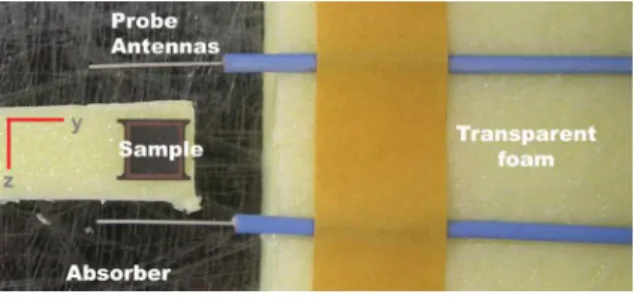
In our experiments, we used two coaxial probe antennae operating at the reactive near field region as transmitter and receiver antennae. We performed measurements by using homemade loop antennas. However, the alignment of the resonator was much easier when we used the probe antennas. For the loop antenna measurements, we had to move the two loop antennas
individually and also it was difficult to see the particle under test during the measurement as the loop antennas had to be placed on the top and bottom of the particle. Moreover, we found out that the probe antennas couple to the resonators better than loop antennas. In the following metamaterial related measurements such as subwavelength imaging it is rather difficult to use loop antennas, as their physical sizes are large and thereby we can not place them close enough to measure subwavelength resolution. Because of these reasons we preferred using probe antennas instead of loop antennas. The sample is inserted into the space between the antennae, wherein we obtained the strongest response, as shown in Fig. 1. There were absorbers placed under the sample and an Agilent N5230A Vector Network Analyzer was used during the experiments. At the magnetic resonance frequency of the particles, we observed a stop-band at the transmission spectra. We determined whether the stop-band was magnetically originated or not by using the concepts of the qualitative effective medium theory [36, 37], i.e. we also measured the shorted version of the MSRRs and observed the disappearance of the stop-band at the magnetic resonance frequency (not shown here).
Fig. 1. Experiment setup
The numerical calculations are performed by using a commercial fullwave code, CST Microwave Studio, which is based on the finite integration technique [38]. The particle under test is inserted into the simulation domain with periodic boundary conditions at the lateral directions (x- and y- directions). In our calculations, the B-field was at the x-direction, the E-field was at the y-direction, and the propagation direction was at the –z-direction, in which we measured the transmitted signals via point probes.
3. Results of the parametric study
3.1. Multi-split ring resonators
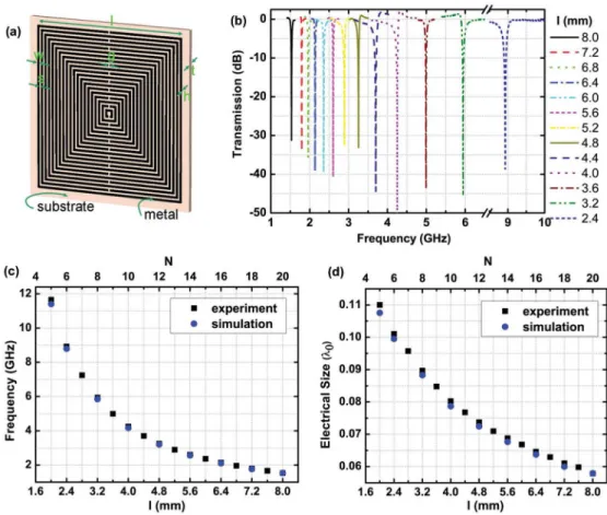
The geometry and parameters of the MSRR particle are shown in Fig. 2(a). The substrate used in our particles was Rogers RT/Duroid 5880 with εr = 2.0 and tanδ = 0.0009. The thickness of
the substrate, t = 254 µm and deposited copper thickness, h = 9 µm. The MSRR parameters were as follows: width of the strips, w = 100 µm, separation between the strips, s = 100 µm, the split width, g = 100 µm, side length of the particles varies from l = 2.4 mm to l = 8.0 mm, and number of rings varies from N = 5 to N = 20. In Fig. 2, we show how the resonant response and electrical size change as we change the side length and the number of rings of the MSRRs, simultaneously. In Ref. [32] we demonstrated the effect of increasing number of rings as side length was fixed. In that work, a standard for the definition of the electrical size was introduced. We identify the radius of the minimum sphere (a) that encloses the particle, and define the physical size as the diameter of this sphere, i.e. 2a. From the minimum of the stop-band, we identify the free space operation wavelength, λ0, and define the electrical size
as u = 2a / λ0. We observed that as we increase the side length via adding new rings to the
particle, the operation frequency decreases, as shown in Fig. 2(c). This result was expected because the increase of physical size decreases the operation frequency in general. On the other hand, the results shown in Fig. 2(d) demonstrated that the electrical size also reduced. These results are in good agreement with the numerical calculations and can be explained by
using the quasi-static LC-circuit models as developed in the theoretical paper of Bilotti et al. [39]. In Fig. 2(b), the resonant response of the MSRRs are shown, in which we obtained quite strong responses and the average of the dip values was on the order of -35 dB. As to the MSRRs, multiple resonances can be seen. However, higher order modes are not under interest for metamaterial related applications since the first magnetic resonance mode provides us the smallest electrical size. In addition, the more we go up in frequency, the electrically larger are the inclusions and, thus, they are not useful anymore as building blocks of metamaterials. The effect of the number of rings (N) while keeping the side length (l) fixed was our first analysis and given in the mentioned Ref. [32]. Changing l, s, and w while keeping N fixed was given in Table I. The structures we studied were composed of discrete elements and we considered almost all the possible parameter changes. Since some parameters are linked to each other, it was not possible to change them independently.
Fig. 2. The multi-split ring resonator (MSRR) response (a) Geometry of the multi-split ring resonator (MSRR), l = 8 mm, w = s = g = 100 µm, h = 9 µm, t = 254 µm. (b) Experimental transmission data as a function of the frequency. (c) Resonance frequency (d) Calculated electrical size as a function of the simultaneously changing N and l.
3.2. Spiral Resonators
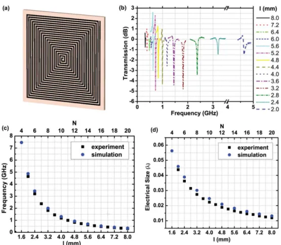
Fig. 3. The spiral resonator (SR) response (a) Geometry of the spiral resonator (SR), l = 8 mm, w = s = 100 µm, h = 9 µm, t = 254 µm. (b) Experimental transmission data as a function of the frequency. (c) Resonance frequency (d) Calculated electrical size as a function of the simultaneously changing N and l.
We also studied the effect of changing the side length and number of turns for the spiral resonators, whose schematic is shown in Fig. 3(a). Similar to the MSRR behavior: as we increased the number of turns the operation frequency decreased and the electrical size also reduced. In Figs. 3(c) and 3(d), after some point the miniaturization factor saturates i.e. adding more turns does not lead to a much smaller electrical size. The miniaturization factor for SRs is larger than MSRRs. The drawback of SRs is that we did not see a strong resonant response. As shown in Fig. 3(b), the minima of the stop-bands are on the order of -2.5 dB on average, which is due to the long length of the metal strips with respect to the operation wavelength. According to the theory developed in Ref [33], the magnetic inclusion can be represented as an RLC series circuit. Therefore, the related quality factor is given by the equation:
(
)
Q= L C R . R accounts for the losses in the material. In the case of the SR, the strip is much longer and the related ohmic losses are quite high. In addition, the capacitance C is higher than in the case of any other resonator here presented. Consequently, the resonance of the SR is expected to be less pronounced if compared to the one of the MSRR. Another way around to see this is to write the quality factor, by definition, as
(
)
(
)
0 stored diss 0
expression. Anyhow, in this form, it is clear that the lower is the resonance frequency, the less pronounced is the resonance. The effect of losses, then, further lowers the resonance strength. This drawback encouraged us to investigate a novel resonator: multi-spiral resonator (MSR).
3.3. Multi-spiral Resonators
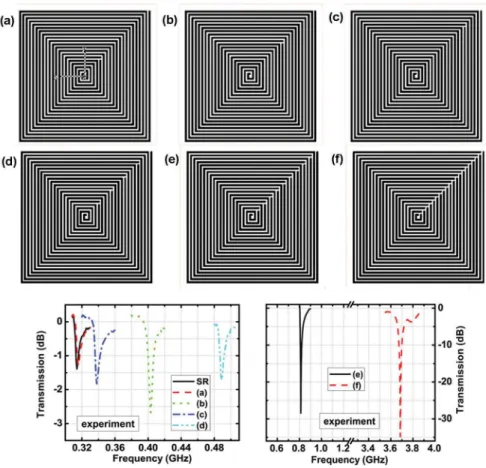
We introduced several splits to the SRs to increase the strength of the resonant response. We fabricated six examples, which are shown in Fig. 4. We introduced one split to the SR particle with N = 20 and l = 8 mm, and changed the position of the split as shown in Figs. 4(a)-4(c). We increased the number of the splits to 4, as shown in Fig. 4(d). However, for these particles the resonant strength was similar to the corresponding SR particle, and we did not observe a significant increase in the resonance strength. We continued in this fashion and obtained the particles as shown in Figs. 4(e) and 4(f) for which a much stronger resonance strength was obtained. The MSR shown in Fig. 4(f) is similar to MSRR shown in Fig. 2(a) geometrically. In this MSR structure, we had a split at every turn similar to the MSRR. As expected the resonance frequency of this structure is almost the same as the MSRR with the same l, N, s and w parameters. The shift at the resonance frequency of the multi-spiral resonator that is shown in Fig. 4(e) is acceptable and it constitutes a good trade-off between the resonance strength and electrical size. Its side length, l = 8 mm and resonance frequency, f0 = 0.81 GHz,
electrical size, u = λ0/30, and stop-band minimum is -27 dB. This particle is low profile and
easy to fabricate, and thereby it is a good candidate for metamaterial applications.
Fig. 4. The multi-spiral resonator (MSR) response. Geometry of the particles analyzed (top). Experimental transmission data of each resonator as a function of frequency (bottom).
3.4. Substrate Effects
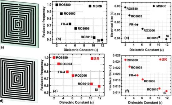
We numerically studied the substrate effects on the design of electrically small negative permeability medium particles. As shown in Figs. 5(a) and 5(d), we selected the MSRR and SR resonators with l = 4 mm, and N = 10 for this analysis. The resonance frequency and electrical size of the particles were calculated for different substrates that are available in the standard printed circuit board and optical lithography processes. In these calculations we ignored the metallic and substrate losses, which do not have any significant effect on the resonance frequency, but do on the simulation time. In Figs. 5(b) and 5(c) we plotted the resonance frequency in reduced units, i.e. we scaled the frequency to the case in which RT 5880 substrate was used. We see that even though the substrate permittivity is a universal scale factor to first order, the MSRR and SR cases do not overlap exactly in Fig. 5. The root of this difference is in the effect of the split capacitance of the MSRR. These capacitances, in fact, sum up with the distributed capacitance between two adjacent rings and do not have a counterpart in the SR case. In Figs. 5(e) and 5(f) we showed that increasing the substrate permittivity approx. 6 times reduced the electrical size by approx. 2 times. Therefore, the miniaturization factor can be improved by using higher permittivity substrates. In our experiments, the substrate was RT/duroid 5880 with εr = 2.0 and we expect higher
miniaturization factors for different substrates, which are shown in Fig. 5.
Fig. 5. (a) Geometry of the multi-split ring resonator (MSRR) particle, N = 10, l = 4 mm, s = w = g = 100 µm. (b), (e) Resonance frequency in reduced units (fred). For the MSRR fred = f0 / (4.17), for SR fred = f0 / (1.307), where 4.17 and 1.307 are the resonance frequency for RT5880 substrate in GHz units, respectively. (d) Geometry of the spiral resonator (SR) particle, N = 10, l = 4 mm, s = w = 100 µm. (c), (f) Calculated electrical size as a function of the substrate permittivity. The permittivity of the substrates: RO5880: ε = 2.0, RO3003: ε = 3.0, FR-4: ε = 4.9, RO3006: ε = 6.15, RO3010: ε = 10.2, Si: ε = 11.9.
3.5. Size scaling of particles and the resonant response at higher frequencies
We finalize this section by searching the limits of the particles that can be produced via the current printed circuit board technology. In Table 1, we showed the measured resonance frequency of the MSRR and SR particles with N = 20, l=20 s+w and the separation
(
)
between the strips (s) and width of the strips (w) were pushed simultaneously down to 50 µm.As the overall particle size reduced the resonance frequency shifted to higher frequencies. By the size scaling of composing individual particles many different combinations of media with controllable permeability can be designed.
Table 1. Geometric parameters and resonance frequencies for the particles (MSRRs and SRs) with a number of rings (turns) N = 20 scaled to operate at higher frequencies. The side length (l), strip width (w), separation between the
strips (s), and resonance frequency (f0) are shown.
s = w (µm) 125 100 75 50
f0 (GHz)
MSRR 1.26 1.55 2.03 3.09
SR - 0.31 0.41 0.60
4. Tunability of multi-split resonators
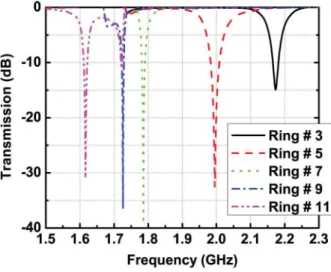
One of the key advantages of the multi-split elements is that they can be tuned by shorting the split-rings independently. We investigated the resonance of a MSRR when one of the splits is closed at a time. Here we fabricated the resonators as shorted. Figure 6 displays the results of digital tunability. As we shorted the second outer most ring (Ring # 3) of the MSRR with N = 12, l = 8 mm, we saw that the resonance frequency shifts from 1.53 GHz to 2.17 GHz. Measurements for the other cases shown in Fig. 6 were also performed. It is possible to short any arbitrary combination of splits, for the MSRR resonator there are 211 combinations each of which will yield to a different resonance frequency. One of the most suitable techniques for tuning multi-split elements is to incorporate photo-switches at the split area of the rings. Photoconducting switches for microwave applications were discussed by Vardaxoglou et al. [40]. In the presented technique a semiconductor substrate is placed or deposited to cover the split area of the rings. When a light is focused on the split region the photoconductor shorts the corresponding ring and the resonator starts to operate at another frequency.
Fig. 6. The shorted multi-split ring resonator (MSRR) response. Here the resonators were fabricated as shorted and photoconductive switches were not used.
5. Enhancement of transmission passing through a subwavelength aperture array by using multi-split resonators
In 1940s Bethe studied transmission and diffraction of light passing through an aperture of size much smaller than the incident wavelength. The transmission efficiency normalized to the aperture area is demonstrated to be dependent on the aperture size and the incoming light
wavelength [41]. By properly deciding the geometry of the metal around the aperture and thereby exciting surface plasmon resonances Ebbesen et. al. demonstrated an enhanced transmission efficiency [42].
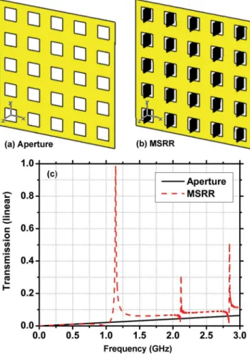
We propose here an alternative solution to enhance the light passing through a subwavelength aperture. We inserted the MSRRs in the hole regions as shown in Fig. 7. In this configuration, the MSRR was excited both electrically and magnetically [43]. At the resonance frequency incident electromagnetic field is strongly localized at around the deep subwavelength element. At each element of the localized modes couple to the free space at the other side of the metallic holes. On the other side, we observe the reemitted radiation of the waveguide modes excited by the elements of the deep subwavelength resonator array. At around the resonance frequency of the MSRR (N = 20, l = 8 mm, s = w = 0.1 mm) the transmission was 98%. Thereby, by utilizing deep subwavelength resonators complete transmission can be achieved from the array of subwavelength apertures.
Fig. 7. (a) Geometry of the subwavelength (a) square hole array only, (b) MSRRs inserted (c) Simulated transmission response of the two cases. At the magnetic resonance frequency of the MSRRs transmission was 0.98.
6. Conclusions
To sum up, we have demonstrated the results of our parametric study on the electrically small negative permeability medium particles that were fabricated via the standard printed circuit board technology. Increasing the side length of the particles and using higher permittivity
substrates in turn decreases the electrical size significantly. On the other hand, there is a trade-off between the electrical size and the resonance strength of the particles. We analyzed a novel particle: the multi-spiral resonator and obtained ~ - 30 dB resonant dip with λ0/30
electrical size at 0.81 GHz. Our particles are low profile and can be easily packed into three-dimensional arrays for antenna, superlens and absorber applications. Moreover, we obtained particles with strip width and separation as low as 50 µm and scaled them to operate at higher frequencies. We explained a method for digitally tuning the resonance frequency of the multi split structures. Finally, we have demonstrated that by inserting deep subwavelength resonators into periodically arranged subwavelength apertures complete transmission enhancement can be obtained at around the magnetic resonance frequency. The proposed application of the enhanced transmission is certainly an example of something extremely interesting for people working in optics and suggests a possible way to obtain it even at near-infrared and visible regimes. The only difference would be in the technology (for instance electron beam lithography instead of regular microwave printed circuit technology).
Acknowledgments
This work is supported by the European Union under the projects EU-METAMORPHOSE, EU-PHOREMOST, EU-PHOME, and EU-ECONAM, and TUBITAK under the Project Numbers 105E066, 105A005, 106E198, and 106A017. One of the authors (E.O.) also acknowledges partial support from the Turkish Academy of Sciences.