A STUDY FROM JUNK MARKET TO THE PRODUCTION OF 5.25% EFFICIENT DYE-SENSITIZED SOLAR CELLS
1Sunay TURKDOGAN
1Department of Electrical and Electronics Engineering and Department of Energy Systems Engineering, Faculty of Engineering, University of Yalova, Yalova, 77200, Turkey
(Geliş/Received: 20.04.2017; Kabul/Accepted in Revised Form: 10.07.2017)
ABSTRACT: This paper reveals that having limited facilities is just an excuse not to do any experimental research in most of the universities and institutions all over the world. This may sound impractical for developed countries; however, it is one of the most fundamental problems for underdeveloped and even for some of the developing countries. In this paper, a study of building a laboratory mostly using homemade devices from junks is explained. This paper might be a good and encouraging reference especially for low-income countries, some universities/institutions with very limited budget around the world as well as some students/researchers who want to have their own tools to conduct a research. After a brief explanation to build some of the tools using junks, the production of dye-sensitized solar cells using homemade equipments with up to 5.25% power conversion efficiency (PCE) will be demonstrated under AM1.5 simulated light emission. Structural, electrical and photovoltaic properties of the fabricated devices will also be investigated using scanning electron microscopy (SEM), X-ray diffraction spectroscopy (XRD), and current-voltage (IV) characterization tools in this paper.
Key Words: Dye-sensitized solar cells, Homemade, Optical tachometer, Oven, Photovoltaics (PV), , Spin coater /
centrifuge.
Hurda Pazarından %5.25 Verimli Boya Duyarlı Güneş Hücrelerinin Üretimine Uzanan Bir Çalışma ÖZ: Bu çalışma birçok üniversite ve kurumda sınırlı donanıma sahip olmanın herhangi bir deneysel araştırma yapılmaması için sadece bir bahane olduğunu ortaya koymaktadır. Bu, gelişmiş ülkeler için garip gelebilir; ancak, az gelişmiş ve bazı gelişmekte olan ülkeler için bile en temel sorunlarından biridir. Bu yazıda, çoğunlukla atık/hurda ev cihazları kullanarak bir laboratuvar oluşturma çalışması ve bu laboratuvardaki cihazları kullanarak boya duyarlı güneş hücrelerinin üretimi anlatılmaktadır. Bu çalışmanın özellikle düşük gelirli ülkeler, çok sınırlı bir bütçeye sahip üniversiteler ve araştırma yapmak isteyen öğrenciler ve araştırmacılar için tetikleyici ve cesaret verici bir referans olacağı düşünülmektedir. Hurda malzemeler kullanılarak tasarlanan bazı cihazların kısaca açıklanmasından sonra, AM1.5 benzetimi altında %5.25 güç dönüşüm verimliliğine (PCE) sahip boya duyarlı güneş hücrelerinin üretimi ev yapımı ekipmanlar kullanılarak gösterilecektir. Üretilen cihazların yapısal, elektriksel ve fotovoltaik özellikleri taramalı elektron mikroskopu (SEM), X-ışınları difraksiyonu (XRD), akım-gerilim (IV) karakterizasyon araçları kullanılarak bu çalışmada araştırılmıştır.
Anahtar Kelimeler: Boya Duyarlı Güneş Hücreleri, Ev Yapımı, Optik Takometre, Etüv, Fotovoltaik, Spin
INTRODUCTION
Studying/working in highly prestigious universities/institutions is the most valuable asset in people’s life as they provide all the necessary facilities and opportunities to conduct world-class research. However the situation in other universities/institutions in a developing stage is not the same because there is no enough budget to purchase all necessary tools to conduct all kinds of research on faculty members’ or students’ demands. As an author of this paper after the utilization of the world’s most advanced laboratories and developing the first semiconductor based monolithic multicolor lasers (Fan et al., 2013; Turkdogan, 2012; Fan et al., 2015; Turkdogan, 2015;) and LEDs (Turkdogan, 2016) in those labs, the limited budget related difficulties were met in a very young university and the story of building the cost effective equipments/tools using junks and their use to build practical devices were essentially drove us to conduct this research.
In this paper, a few homemade devices along with few commercial ones were employed. Centrifuge, magnetic stirrer and spin coater were designed using high rpm brushless HDD motor with the control circuits and the optical tachometer was designed using Arduino Nano Board. In addition to those a homemade furnace was also designed by transforming a regular residential-type salvage oven into a precisely temperature controllable scientific grade furnace via PID temperature controller (REX-C100), solid-state relay (FOTEK SSR-40A) and K-type thermocouple. Although all these devices are enough to conduct a research on an emerging technology of dye-sensitized solar cells and some others, we are also developing new equipments such as DC magnetron sputter coater, PID controlled split hinge tube furnace and pyranometer from junks. Our aim by designing such low cost tools is to bring the science and research for everyone at anywhere. After building all these tools, we are going to employ them to create new projects in the field of photonics/optoelectronics and those are going to bring high value-added devices. In the literature there are similar works explaining the production of scientific grade equipments from junks (Bianchi et al., 2006; El-Agez and Taya, 2014) but this paper is going to be its first kind explaining the production of more than one equipment as well as their use to fabricate/construct a practical device.
In addition to explaining the development of the equipments from junks, the secondary aim of this research is to build dye-sensitized solar cells with relatively high power conversion efficiency (PCE). The increasing demand for energy forces us to seek new energy sources and those should come from clean energy sources for a sustainable world. Sun is the main source of all renewable energies (wind, tides, biomass, hydro and solar) with the exception of geothermal and among all these options solar energy is the most dependable and able to cover the world energy demand (Ellabban et al., 2014; Gevorkian, 2007). The energy emitted by sun in just one hour is able to meet the world’s annual energy demand. Since it has that huge potential, a great number of people are working on the improvement of photovoltaic cells, which directly transform sun light into electricity. In order to bring the cost of electricity produced by PV cells down new materials and device architectures should be used or the efficiency of current commercial cells should be increased by some techniques because the cost of energy produced by PV cells is still high compared to the energy produced from conventional sources (IEA, 2014; Feldman, 2014; Shankleman and Martin, 2017). PV cells are grouped as 1st generation (sc-Si, poly-Si, a-Si), 2nd generation (Thin films - CdTE, CIGS) and 3rd generation (Nanostructure based, Organic, Perovskite, Dye-sensitized, CZTS solar cells) and each cell technology has its own advantages and disadvantages compared to each other (Parida et al., 2011). Since the fabrication process of the DSSCs are relatively easy (Gratzel, 2003) compared to the widely used 1st and 2nd generation solar cells such as sc-Si, poly-sc-Si, CdTe thin film, a dye-sensitized solar cell is going to be built using the aforementioned equipments as a proof of concept. Although DSSCs are not comparable with the current commercial PV cells at the current stage they show a great promise as they are less sensitive to impurities, temperature and angle of incident light, they have relatively high PCE and they can be fabricated with low cost on either flexible or rigid substrates (Jose et al., 2009).
MATERIALS AND METHOD
The details of designing homemade equipments from junks and fabrication of dye-sensitized solar cells with the characterization methods will be given in the subsections below.
Building a Homemade PID Controlled Laboratory Oven
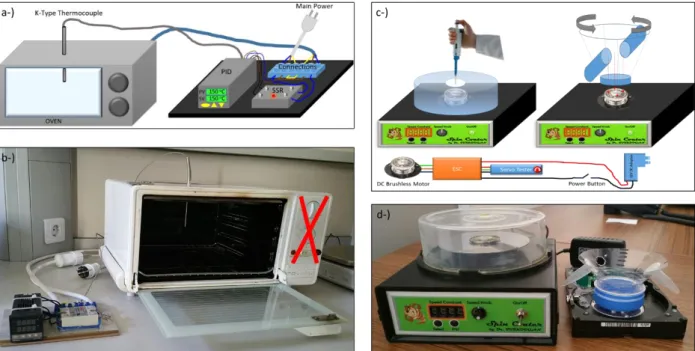
A must have laboratory ovens provide uniform temperature throughput and can be used for various applications such as drying, curing, annealing, and so on with the temperature range over 350°C. In order to build an oven which is needed for synthesizing the materials and annealing the samples in our case a salvage residential type oven was purchased from a junk market for $4. The analog thermometer of the oven was broken, but the heating elements were in a working condition. That was what we actually needed because temperature could be controlled via PID controller (REX-C100) and a K-type thermocouple more precisely. In order to do that K-type thermocouple ($4) was inserted into center of the oven from the top side (see Fig. 1a-b) and the temperature value was read by a PID controller ($14 w/ SSR). PID controller keeps the set value inside the oven by switching on and off the solid state relay which supplies energy to the heating elements. Bottom and top resistances of the oven are connected in series to lower the flowing current through the heating elements and therefore this slow down the heating up rate compared to only one-resistance or parallel resistances in use (1000W vs. 2000W & 4000W). The control circuit is suitable to control the temperature between 25-1000°C, but due to the type of heating elements used in the oven our controllable temperature range is limited between 25-350°C. Instead of buying an oven for $1000 we paid only $22 in total and designed a precisely temperature controllable oven which can be comparable to the commercial ones.
Building a Homemade Spin Coater
Spin coater is a widely used tool especially in semiconductor processing and it is used to deposit uniform thin films to a flat substrate through the centrifugal force. When the substrate is rotated at high rpms, the substance (coating material) is spread over by centrifugal force and the thickness of the uniform coating becomes inversely proportional to the square root of the spinning speed (Scriven, 1988). The thickness also depends on the viscosity of the coating materials. Commercial spin coaters usually cost thousands of dollars. In order to design a homemade spin coater with very low cost a 3-phase 9600rpm brushless DC motor recovered from a junk HDD was used as a main part. Motor was controlled using an Electronic Speed Controller (ESC) (XXD HW30A) which is widely used among hobbyists. In order to control ESC we employed an inexpensive servo motor tester (HJ Digital Servo Tester/ESC), which has a reading on it depending on the pulse-duty ratio of the signal sent to servos or ESCs. By connecting all these together as illustrated in the bottom of Fig. 1c and placing all the electronics inside a plastic box and high rpm motor on top of the box with a CD case with holes on it to introduce the coating material, a spin coater was built with extremely low cost. (HDD: 1$, ESC: 6$, Servo Tester: 6$, Plastic Box: 2$, CD case: 0.5$, power switch: 0.5$, 12V power supply: 2$ and 18$ in total compared to thousands of dollars) With our spin coater, double-sided tape should be used to fix the substrate to the rotor, but a chuck with a groove to secure the substrate is another option for a vacuum free spin coater.
Building Homemade Centrifuge and Magnetic Stirrer
Centrifuge machine is another tool widely used in laboratories. It puts an object in rotation around a fixed axis. Sedimentation principle is the main working principle in which the centripetal acceleration causes denser substances and particles to move outward in the radial direction while the less dense objects are displaced and move to the center. In our case a laboratory centrifuge is used to sediment the
synthesized powder which will be dissolved in another solvent and used to be coated on the substrate. In order to design a centrifugal machine the spin coater was utilized because the idea is the same but the only difference is the purpose. Instead of putting substrates onto a spinning plane we need to put vials in an angle and pointing outward direction to utilize the centrifugal force. Since a spin coater was already designed, we used the same device, but converted it to a centrifuge by placing the neck of a plastic bottle with some holes on it to hold the vials as seen in Fig. 1c-d. In order to keep the balance and eliminate any vibration we need to put the same amount of sample to the opposite slots. Since 5lt plastic water bottle is free of charge cost of the centrifuge also came out free. In addition to all those, a strong magnet recovered from a junk HDD was attached to the rotor and with the help of a stage (CD case) to hold the beakers over the magnet spin coater was utilized as a magnetic stirrer. In another words the cost of spin coater, centrifuge and magnetic stirrer all able to spin up to 9600rpm is 18$ in total.
Figure 1. Schematic illustrations and real color images of homemade laboratory oven (a-b), spin coater and centrifuge (c-d). Bottom part of (c) shows the electronic control diagram of spin coater, centrifuge
and magnetic stirrer. Designing an Optical Tachometer using a Microprocessor
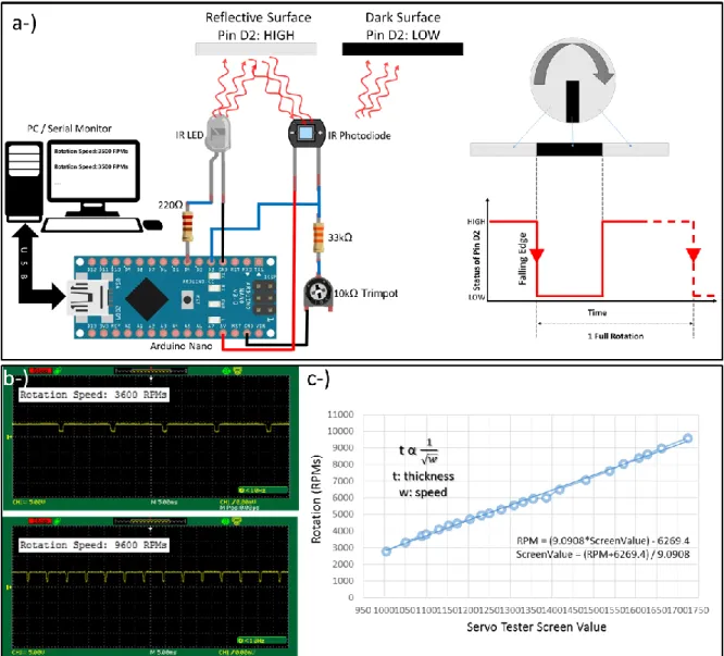
In order to measure the rotation speed of the spin coater and centrifuge an optical tachometer was designed utilizing Arduino microcontroller with two resistors and IR LED-photodiode pair taken from a salvage computer mouse. As mentioned in the previous paragraphs 3 phase brushless DC motor recovered from a junk HDD is controlled using an ESC which is widely used among hobbyists. In order to control ESC we employed an inexpensive servo motor tester, which has a reading on it depending on the pulse-duty ratio of the signal sent to servos or ESCs. For the sake of easiness, this value was aimed to be taken as a reference to give speed information. In order to do the transformation an optical tachometer was needed. Figure 2 shows the circuit diagram of the optical tachometer designed and it basically measures how many transition from high to low occurs in a second and then transforms this value by multiplying by 60 to get rpm value by considering the number of triggering black tapes adhered on the spinning plane. This value was reflected on either LCD display or PC serial monitor. Since a black sticky tape was placed on the rotating reflective plane and so that for each rotation we get a trigger from high to low and by utilizing Arduino’s interrupt function rpm value was figured out. The photodiode in the circuit was used in photoconductive mode and therefore it was reverse biased and the current flowing from the PD due to incident IR light is transformed into processable voltage signal via
resistors connected in series to PD. Besides fixed resistor a trimpot was also used to adjust the detection sensitivity of the transition from reflective to dark surface(s). The codes used with Arduino are given in Appendix 1 and by using those codes and given circuit diagram everyone can build their own optical tachometer for various purposes.
Figure 2b shows the captured oscilloscope screens of Pin D2 (Interrupt 0) when the spin coater was spinning at 3600 and 9600 rpms, respectively. As seen from the curves when the reflective surface faces the PD, signal at “pin D2” becomes logic “HIGH” and when it faces dark sticky tape the same pin changes the logic status and becomes “LOW”. As shown in Fig. 2b as the spinning speed increases the number of transition in a given time increases and this is reflected in terms of RPMs on the serial monitor (Figure 2b insets). By utilizing the designed optical tachometer a number of values read in the servo tester were tested and their real rpm values saved. By plotting rotation speed vs. Servo tester reading in Fig. 2c we figured out their dependence and any rotation speed required by user can be found in terms of servo tester reading value using the extrapolated formula and adjusted accordingly.
Figure 2. (a) Schematic of the optical tachometer with the illustration of photodetectors’s signal as PD facing the reflective and dark surfaces on the spinning plane. (b) Pin D2’s signal input taken from the
Oscilloscope screen when the spin coater rotates at 3600rpms and 9600rpms, respectively. Insets with white background show the serial monitor output. (c) Rotation speed of the spin coater as a function of
The way we followed in this research is somewhat indirect, but we areplanning to design a motor driver circuit, which is going to give an option of putting the required rotation speed directly.
Fabrication of Dye-Sensitized Solar Cells
In order to fabricate a dye-synthesized solar cell within the scope of this paper TiO2 and ZnO tandem layers as photoanode and conventional Pt counter electrodes were employed. ZnO nanostructures were hydrothermally synthesized and Titanium(IV) Oxide nanoparticles purchased from Sigma Aldrich was used as is. Zinc Nitrate hexahydrate was used as a source material for ZnO and 60mg of Zn(NO3)2 .6H2O was dissolved in 40ml deionized water under magnetic stirring. A few drops of Ammonia were added into the solution to adjust the pH level to 10 and then the whole solution was poured into a Teflon lined stainless steel autoclave (Kilic et al., 2012; Kilic and Çelik, 2015). ZnO nanoparticles were synthesized at 200°C for the course of 8 hours. Precipitated products after the growth of ZnO were centrifuged at 5400rpm for 10min to obtain ZnO powder. The collected powder at the bottom of the vials was dried at 100°C for an hour in the oven and then both TiO2 nanoparticles and ZnO powder were dissolved by Nitric Acid in the milk consistency to be coated on the ITO layer. Since the work function of TiO2 is smaller than that of ZnO (Ji et al., 2012), TiO2 layer was first coated via spin coater rotating at 4000rpm for 2 min and then annealed at 300°C for half an hour. After that ZnO was spin coated over ITO/TiO2 at 5000rpm for about 2min and followed by annealing at 300°C for an hour. N719 dye molecules were adsorbed by the photoanode and KI/I3 electrolyte was used as redox couples. To construct the cell (ITO/TiO2/ZnO/N719) / (Pt/ITO) layers were sandwiched by binder clips (see Fig. 4b) and electrolyte was introduced between counter electrode and sensitized photoanode by capillary force and cell became ready for the IV measurements.
Characterization Methods
The structural properties of the samples were carried out using scanning electron microscope (SEM- FEI QUANTA FRG 450) at 15kV and chemical compositions of the constituent materials were figured out using energy dispersive spectroscopy (EDS) detector embedded in the SEM microscope. Crystallographic properties, phases and structural quality were investigated by x-ray diffraction (XRD- figure out the electrical and photovoltaic properties were performed using Keithley 2400 SourceMeter under dark and AM 1.5 simulated light emission.
RESULTS AND DISCUSSION
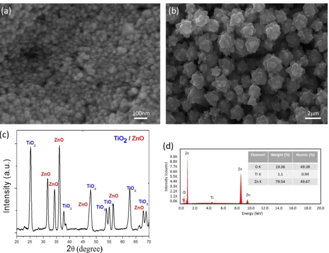
SEM images in Fig.3a-b show the typical morphologies of TiO2 nanoparticles and synthesized ZnO nanostructures. As seen in Fig. 3a the coated spherical particles are 20-30nm in diameter and 3D ZnO nanostructures seen in Fig. 3b have 3D
flower-By changing the pH value of the solution before hydrothermal growth morphology of the structures can be tuned. EDS analysis result in Fig.3d proved that the prepared hybrid photoanode has the composition of Zn, O and Ti; however, since the penetration depth of electrons is around 1um in the EDS analysis we see only a tiny bit amount of Ti which comes from the bottom layer of TiO2. If we exclude the Ti peak we can say that the products are perfectly stoichiometric and have no significant defects. XRD spectra in Fig. 3c show that photoanode constituent materials, TiO2 and ZnO, exhibit sharp peaks therefore very high crystalline quality and the characteristic peaks of TiO2 and ZnO films are centered at 25.17, 37.7, 47.81 degrees and 31.59, 34.19, 36.05 degrees, respectively. Those peaks are well matched with the diffraction lines of the materials seen in the literature (Downs and Hall-Wallace, 2003) and correspond respectively to (210), (102), and (321) for TiO2 and to (100), (002) and (101) for ZnO.
Figure 3. Top view SEM images of (a) TiO2 and (b) ZnO nanostructures. (c) XRD spectra of TiO2/ZnO hybrid structures in the photoanode region where we see the characteristic peaks of both TiO2 and ZnO. (d) EDS spectra of TiO2/ZnO hybrid structures with the quantification results that prove
the formation of ZnO on top of TiO2.
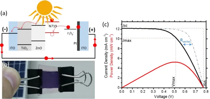
Photovoltaic properties of DSSC constructed with ITO/TiO2/ZnO/N719 photoanode and Pt/ITO CE were investigated under solar simulator with AM1.5G simulated solar radiation. The layers and band alignment (Ji et al., 2012) with the movement of electrons as a result of photon absorption is shown in Fig. 4a and constructed solar cell’s real color image is seen in Fig. 4b. Photovoltaic properties of the cell are very promising and it exhibits 5.25% power conversion efficiency. Although it is not the upper limit of DSSC technology (the highest efficiency is 11.9% (Green et al., 2017)) it is relatively high considering that the cells were fabricated with very low cost and using homemade laboratory equipments. IV measurements of the cells with 0.25 cm2 active surface area (mask with 0.25 cm2 holes was used) were performed and all the photovoltaic properties is given in Table 1. It is worth to note that the role of ZnO on top of TiO2 is to increase the conductivity and charge collection efficiency through the interface engineering and it is believed to be the reason of getting relatively high efficiency from such cells. On the other hand 3D ZnO structures with many branches provide a large surface area for the adsorption of dye molecules and therefore increased number of photon absorber molecules with a better band alignment cause to increase the short circuit current of the cells. In Fig. 4c Rseries resistance was indicated and that would be fixed using some intermediate materials such as graphene and carbon nanotube in both photoanode and CE region to decrease the transition resistance and increase the conductivity. Researchers around the world utilized those and the results show a great improvement on the PCE of the solar cells (Sun et al., 2010; Yang et al., 2010; Yang et al., 2013; Kilic et al., 2016).
Figure 4. (a) Schematic illustration of TiO2/ZnO hybrid structure based DSSC w/ Pt counter electrode (b) Real color image of the constructed cell. (c) JV and PV curves of the corresponding solar cell
with the indication of some important parameters.
Table 1. Photovoltaic properties of DSSCs based on TiO2/ZnO photoanode w/ Pt counter electrode under AM 1.5G simulated light emission (100mW/cm2).
CONCLUSION
We highly believe that this work is going to encourage a great number of people and stimulate them to initiate a research in different fields in which case they do not have enough facility. It is believed to be a valuable guiding reference for diverse communities. This work is of great interest for the development of new equipments, tools as well as functional devices in many areas. Although we utilized the homemade equipments for dye-sensitized solar cells, they are of more great interest for the production of other emerging solar cell technologies such as perovskites and organics. We brought the cost of the aforementioned devices down to tens of dollars compared to thousands of dollars. This study not only bring the price of laboratory equipments down to several dollars but also become an encouraging and explanatory guide for a wide community. In addition to encouraging the people to be more creative and producing inexpensive convenient devices this paper reveals important results for the clean and green energy future. DSSCs with TiO2/ZnO tandem construction was demonstrated with 5.25% PCE and they show a great promise to replace the conventional energy sources; however, the drawbacks of DSSCs in general should be addressed before commercialization and we need to work further to optimize our cells to increase the conversion efficiency.
ACKNOWLEDGEMENT
We would like to thank Assoc. Prof. Dr. Bayram KILIC for his encouragement on this exciting research and having fruitful discussions about dye-sensitized solar cells.
REFERENCES
Bianchi, R. F., Panssiera, M. F., Lima, J. P. H., Yagura, L., Andrade, A. M., Faria, R. M., 2006, "Spin Coater based on Brushless DC Motor of Hard Disk Drivers", Progress in Organic Coatings, Vol. 57, No. 1, pp. 33-36.
Downs, R. T., Hall-Wallace, M., 2003, "The American Mineralogist Crystal Structure Database", American Mineralogist, Vol. 88, pp. 247-250.
El-Agez, T. M., Taya, S. A., 2014 "Design of a Spectroscopic Ellipsometer by Synchronous Rotation of the Polarizer and Analyzer in Oppositedirections", Microwave and Optical Technology Letters, Vol. 56, No. 12, pp. 2822–2826.
Ellabban, O., Abu-Rub, H., Blaabjerg, F., 2014, "Renewable Energy Resources: Current Status, Future Prospects and Their Enabling Technology", Renewable and Sustainable Energy Reviews, Vol. 39, pp. 748–764.
Fan, F., Liu, Z., Yin, L., Nichols, P. L., Ning, H., Turkdogan, S., Ning, C. Z., 2013, "Simultaneous Two-Color Lasing in a Single CdSSe Heterostructure Nanosheet", Semiconductor Science and Technology, Vol. 28, No. 6, pp. 065005.
Fan, F., Turkdogan, S., Liu, Z., Shelhammer, D., Ning, C. Z., 2015, "A Monolithic White Laser", Nature Nanotechnology, Vol. 10, No. 9, pp. 796-803.
Feldman, D., 2014, Photovoltaic (PV) Pricing Trends: Historical, Recent, And Near-Term Projections, https://escholarship.org/uc/item/06b4h95q
Gratzel, M., 2003, "Dye-sensitized Solar Cell", Journal of Photochemistry and Photobiology C, Vol. 4, pp. 145– 153.
Gevorkian, P., 2007, Sustainable Energy Systems Engineering: The Complete Green Building Design Resource, McGraw Hill Professional.
Green, M. A., Emery, K., Hishikawa, Y., Warta, W., Dunlop, E. D., 2017, "Solar Cell Efficiency Tables (Version 49)", Progress in Photovoltaics: Research and Applications, Vol. 25, pp. 3-13.
IEA, 2014, Technology Roadmap: Solar Photovoltaic Energy.
Jose, R., Thavasi, V., Ramakrishna, S., 2009, "Metal Oxides for Dye‐Sensitized Solar Cells", Journal of the American Ceramic Society, Vol. 92, no. 2, pp. 289-301.
Ji, I., Park, M. J., Jung, J. Y., Choi, M. J., Lee, Y. W., Lee, J. H., Bang, J. H., 2012, "One-dimensional Core/Shell Structured TiO 2/ZnO Heterojunction for Improved Photoelectrochemical Performance", Bulletin of the Korean Chemical Society, Vol. 33, No. 7, pp. 2200-2206.
Shankleman, J., Martin, C., 2017, "Solar Could Beat Coal to Become the Cheapest Power on Earth". Bloomberg View, Bloomberg LP, Retrieved 3 January 2017.
Kilic, B., Omay, D., Kosa, E., Trabzon, L., Kizil, H., 2012, "Growth of ZnO Nanostructures on Biopolymer Films", Journal of Materials Science and Engineering A, Vol. 2, No. 12A, pp. 761.
Kılıç, B., Çelik, V, 2015, "Self-assembled Growth of Tandem Nanostructures based on TiO2 Mesoporous/ZnO Nanowire Arrays and Their Optoelectronic and Photoluminescence Properties", Applied Physics A, Vol. 119, No. 2, pp. 783-790.
Kilic, B., Turkdogan, S., Astam, A., Ozer, O. C., Asgin, M., Cebeci, H., Urk, D., Mucur, S. P., 2016, "Preparation of Carbon Nanotube/TiO2 Mesoporous Hybrid Photoanode with Iron Pyrite (FeS2) Thin Films Counter Electrodes for Dye-Sensitized Solar Cell", Scientific Reports, Vol. 6, pp. 27052.
Levelized Cost and Levelized Avoided Cost of New Generation Resources, US Energy Information Administration, Annual Energy Audit 2016, 5 Aug. 2016.
Parida, B., Iniyan, S., Goic, R., 2011, “A Review of Solar Photovoltaic Technologies”, Renewable and Sustainable Energy Reviews, Vol. 15, no. 3, pp. 1625-1636.
Scriven, L. E., 1988, "Physics and Applications of Dip Coating and Spin Coating", In MRS Proceedings, Vol. 121, pp. 717.
Sun, S., Gao, L., Liu, Y., 2010, "Enhanced Dye-Sensitized Solar Cell using Graphene-TiO2 Photoanode Prepared by Heterogeneous Coagulation", Applied Physics Letters, Vol. 96, No. 8, pp. 083113. Turkdogan, S., 2012, Nanowire Synthesis and Characterization: Erbium Chloride Silicate and Two Segment
Cadmium Sulfide-Cadmium Selenide Nanowires and Belts, Master Thesis, Arizona State University, Electrical Engineering, Tempe.
Turkdogan, S., 2015, Growth and Characterization of Multisegment Chalcogenide Alloy Nanostructures for Photonic Applications in a Wide Spectral Range, PhD Dissertation, Arizona State University, Electrical Engineering, Tempe.
Turkdogan, S., Fan, F., Ning, C. Z., 2016, "Color‐Temperature Tuning and Control of Trichromatic White Light Emission from a Multisegment ZnCdSSe Heterostructure Nanosheet", Advanced Functional Materials, Vol. 26, No. 46, pp. 8521-8526.
Yang, N., Zhai, J., Wang, D., Chen, Y., Jiang, L., 2010, "Two-dimensional Graphene Bridges Enhanced Photoinduced Charge Transport in Dye-Sensitized Solar Cells", ACS Nano, Vol. 4, No. 2, pp. 887-894.
Yang, Z., Liu, M., Zhang, C., Tjiu, W. W., Liu, T., Peng, H., 2013, "Carbon Nanotubes Bridged with Graphene Nanoribbons and Their Use in High‐Efficiency Dye‐Sensitized Solar Cells", Angewandte Chemie International Edition, Vol. 52, No. 14, pp. 3996-3999.
APPENDICES
Appendix 1. Arduino codes for the optical tachometer #define irLED 4 // The Infrared LED is connected to pin#4 volatile byte intNum; // "volatile" should be used with interrupts unsigned int rpm; //rpm might be either negative or positive
int mtime=1000; //Measurement time in which number of interrupts were detected. Min detectable rpm becomes 60*1000/mtime.
int ntape=1; //Number of tape on a rotating plane void int_count() // Counting the number of interrupts {
intNum++; //each interrupt increases the intNum by 1 }
void setup() {
Serial.begin(9600);
attachInterrupt(0, int_count, FALLING); //IR dedector is connected to pin 2 which is interrupt 0. Triggers when it goes from HIGH to LOW and calls int_count.
pinMode(irLED, OUTPUT); // Make irLED pin output digitalWrite(irLED, HIGH); // Turn on IR LED
intNum = 0; rpm = 0; }
void loop() {
delay(mtime); // Update RPM every defined millisecond (mtime)
rpm = (60 * 1000 * intNum / mtime / ntape); // Calculates the rotation per minute depending on the measure time and # of triggering tapes on the spinning plane.
Serial.print("Rotation Speed: "); Serial.print(rpm);
Serial.println(" RPMs"); Serial.println();
intNum = 0;
attachInterrupt(0, int_count, FALLING); //Restart the interrupt processing }