489 METALURGIJA 52 (2013) 4, 489-492
L. DAHIL, A. KARABULUT, S. BASPINAR
DAMPING PROPERTIES OF OPEN PORE ALUMINUM
FOAMS PRODUCED BY VACUUM CASTING
AND NaCl DISSOLUTION PROCESS
Received – Prispjelo: 2013-02-05 Accepted – Prihvaćeno: 2013-04-20 Preliminary Note – Prethodno priopćenje ISSN 0543-5846 METABK 52(4) 489-492 (2013) UDC – UDK 669.71:539.21:539.67:530-145=111
L. Dahil, Istanbul Arel University, Department of Mechanical and Metal Technologies, Turkey, A. Karabulut, Afyon Kocatepe University, Faculty of Technology, MechanicalEngineering, Turkey, S. Baspınar, Afyon Ko-catepe University, Technical EducationFaculty, Turkey
In this study,damping ratios of 3 samples made of aluminum foam material, which have diff erent-density pores, were calculated, the eff ects pore density on damping were examined. Experimental modal analysis method was used for examining of the eff ects of the pore density on damping. In experimental modal analysis method, frequency charts were obtained by driving to the sample with a hammer. Through these frequency charts, damping ratios of each 3 samples were calculated with ME’scope VES program. It was observed in calculated damping ratios that pore density has infl uences on damping; thus, damping accordingly increases as the number of pores increases. It is seen that criti-cal damping constant decreases as the material structure changes in terms of volume and density.
Key words: aluminum foam material, pore, damping, vibration
INTRODUCTION
Nowadays, metallic foam materials become increas-ingly more important due to their specifi c properties. Energy absorption ability of metallic foam materials is high and they have abilities such as lightness, thermal insulation and damping resistance. Aluminum based metallic foams, especially, takes a great part in engi-neering practices. Aluminum foams can absorb more energy than many metals.
Besides, variety and ease of use of these metallic foams in the areas of usage make these materials a re-search subject. Metallic foams are a kind of cellular structures such as wood, corap and sponge. They are not natural products. ‘Foam’ term cannot explain the exact mean.
A sponge-shaped and open-porous structure occurs rather thana foam. So, it is generally stated as ‘metallic foam’
Nowadays, metallic foams are produced from many metals. Metallic foams have a porous structure such like a sponge. Porous structure is obtained through special methods. Dimensions of the pores affect to the mechan-ic properties.
Damping coeffi cient depends on the porosity of po-rous material. Damping increases with increasing the porosity. Damping coeffi cient of porous magnesium is greater than non-porous magnesium. Mechanical dam-ping in cellular metallic materials depends on structural factors and test conditions [1]. Researches about the
us-ing of HIDAMETS alloys, which have NİTİ shape logi-cal due to their high damping property, in the active and passive shock, vibration and noise controls, have been continue [2]. Vibration damping of a hollow short-trunk added-elbowed beam with granular items is modeled and is examined. The source of damping is granular items that fi ll relatively the short trunk; thus, inner fric-tion contact can cause a great deal of energy loss; this helps to the structure for vibration damping [3]. In civil structures, it is frequently benefi ted from viscous-fl ow damping tools to prevent vibrations of earthquake and wind. It has been realized that viscous-fl ow damping is a powerful and economic energy damping to develop seismic resistances of structures [4]. In room tempera-ture, thermoelastic damping’s effect is broader than air damping’s effect to the micro beam resonators [5]. Fi-nite element modeling of fl exure damping of the loose wire cables are examined by using homogenized Ray-leigh damping [6]. Shape logical alloy rod is formed to examine the macroscopic damping effects were set off by fi rst rank phase transformation [7]. Behaviors of Free layer damping (FLD) beams were analyzed. As a nu-meric example, dynamic behavior of cantilever beams was studied [8]. It was studied on unnatural damping, with Mutigrid (MG) method and coarse grid method, to the solution of high oscillatory problems [9]. Simula-tion working was made for the effect of suspension damping on tool drive [10]. Experimental evidence of thermoelastic damping, in silicon diapausing, was made [11]. In our study, by using experimental modal analysis method, we calculated damping of 3 samples are manu-factured from aluminum foamwhich has different den-sity pore, researched the effect of pore denden-sity on damp-ing.
490 METALURGIJA 52 (2013) 4, 489-492 L. DAHIL et al.: DAMPING PROPERTIES OF OPEN PORE ALUMINUM FOAMS PRODUCED BY VACUUM CASTING...
MATERIALS AND METHODS
Production of Aluminum Foam Materials
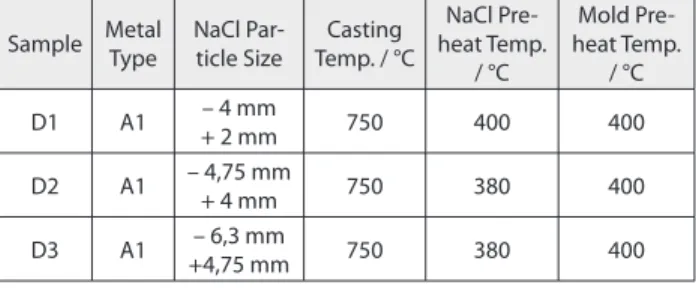
Figure 1shows the design of the vacuum casting sys-tem. System contains vacuum chamber, mold holder, gage and valves. Aluminum fi lter was used to prevent escaping of the free NaCl space holders to the vacuum line. 50mmx100mm (inner diameter x height) steel mold was used for the casting. Pure aluminum was used for the metal foam production. Description of the sam-ples, production parameters are given in Table 1. Stand-ard samples were produced and production variables were determined by trial and error method with several attempt. - 0,8 bar vacuum was applied for the all sample series. NaCl particle was crushed and seized from the bulk NaCl rock. Aluminum was melted in the SiC cru-cibles. Both mold and NaCl were heated before the casting. By preheating, sudden solidifi cation of the melt on the mold and NaCl space holder surfaces were pre-vented. Therefore, better infi ltration conditions created. Table 1 Sample types and production parameters
Sample Metal Type NaCl Par-ticle Size Casting Temp. / °C NaCl Pre-heat Temp. / °C Mold Pre-heat Temp. / °C D1 A1 – 4 mm + 2 mm 750 400 400 D2 A1 – 4,75 mm + 4 mm 750 380 400 D3 A1 – 6,3 mm +4,75 mm 750 380 400
NaCl preheat temperature decreased with increasing space holder size. When the space holder size increased, infi ltration became easier than smaller particle size.
Before the casting, heated NaCl particles were fi lled approximately 75% fi ll height of the heated mold for all sample series. Temperature of the mold and NaCl parti-cles were measured by optical pyrometer. After casting, samples were cut into 50x70 mm (diameter x height) size. Figure 2 shows the differentresulting cross section of the foams.
In Figure 2 samples since the samples have open cell structure waterimmersionmethod for the density meas-urements cannot be applied to the samples. Density of the samples was measured by calculating simple mass/ volume ratio of the samples. For this purpose, samples were prepared to regular shape by mill cutter (Figure 1). Young modulus and plastic collapse strength (or plateau stress) read from the deformation curves. Young modu-lus calculated from the slope of the elastic region of the deformation curves. Relative densities were calculated for the determination of the %pore volume by dividing density values to the density of the metal without pores. Density of the Al was taken as 2,7 gr/cm3. Compressive test was applied with a deformation speed of 1mm/min until 50% deformation.
Table 2 Strength-density relation of the metallic foams Sample E /GPa σpl /MPa Relative Density /ρ*/ρk ρ* gr/cm3 % Porevo-lume D1 2,5 7,50 0,352 0,951 64,8 D2 1,0 1,65 0,347 0,937 65,3 D3 1,0 1,01 0,332 0,896 66,8
Vibration Analysis
Experimental modal analysis has been recently used in many researches. Theoretical and experimental stud-ies have been made in determining of vibration charac-teristics of a structure. Modal analysis has been used in examining of complex structures. By using modal anal-ysis method, it is possible to obtain the dynamic charac-teristics which include the mode shape that is a value depends on a natural frequency, damping ratio and structural deformation of a structure.
Among the causes of need to experimental modal analysis, mathematical model of system is set off while the theoretical analysis of the systems is done. The re-sults obtained by experimental are compared with the results obtained from mathematical model. Accuracy of mathematical model is thereforedemonstrated.
To design a machine, we need to the defi nition of resonance and to know how will be the reaction of sys-tem when a force is applied to the syssys-tem. Mode shapes and vibration type of system will be useful for the engi-neer in designing of system. Modal analysis can vali-date analytical model in use, if results are proper with physical model, this analytical model can be used for the further changes and analyses. In addition, it helps Figure 1 Vacuum casting system
491 METALURGIJA 52 (2013) 4, 489-492
L. DAHIL et al.: DAMPING PROPERTIES OF OPEN PORE ALUMINUM FOAMS PRODUCED BY VACUUM CASTING...
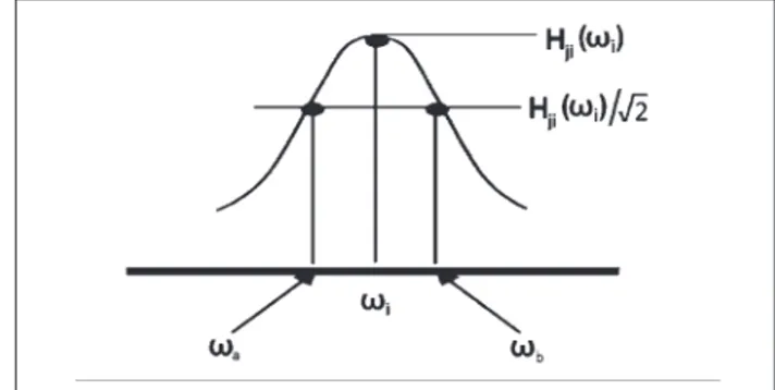
tics. By using FRF diagrams, damping ratio can be found as ζ value. As shown at Figure 4.ωaandωbvalues are acquired by dividing peak point of FRF diagram into 2 . Here,ωiis resonance frequency.
According to these, damping ratio can be found by using = equation. The effect of peak point value, ωitakes a big part in damping ratio.
Experimental Apparatus
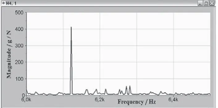
Magnitude frequency values were acquired, after the 3 samples, which were used in study, had been sepa-rately subjected to vibration analysis.
Testing apparatus, which was used in our study, is shown at Figure 5.The samples were hung, elongation, to a fi xed point with a thin rubber in order to be meas-ured through the multiple DOF system.Accelerometer was separately connected to 3 points, and was hit with a hammer from 3 different points. Thus, in total, 9 fre-quency charts were acquired. Damping ratios were ob-tained from these obob-tained frequency-magnitude charts.
Figure 6, 7 and 8 showsthedampingratewas ob-tainedfrequency-magnitude graphics and these charts puts in order from with minimal pores to with maxi-mum pores.
determining of structural weaknesses as getting how can be moved dynamically; besides, it will be useful for resolving the problems of noise and vibration. At the same time, the measurements that are periodically done have been vital needs in order to being worked of looms andstructures in the proper safe operating environ-ments.
Experimental Modal Analysis
In experimental modal analysis method, a force is applied to the system and reaction of the system to this force is measured. A hammer is used for applying a force to the system, an accelerometer is used for meas-uring the reaction of the system and a signal analyzer is used for evaluating obtained data.
The most important measurement values required to modal analyses are (Fourier Response Function) FRF. Simply, it’s the percentage of exit response to entry force. For this measurement, it should be used FFT (Fast Fourier Transform) analyzer or a program that performs FFT functions.
By using FFT that provides Fourier transform, ac-tion-reaction functions are transformed from time envi-ronment into frequency envienvi-ronment.
By using frequency behavior functions, natural fre-quencies, mode shapes and damping ratios of system are determined. A FRF occurs between each drive point and measuring point. All collected data can be consid-ered as matrix of FRF. Each line shows a response point and each pillar shows the drive point.
Many machines and structures are constant systems that involve infi nitely manydegrees of freedom. But, load affects from fi nite number point (from degree of freedom) in practical tests and the response is measured from fi nite number point (degree of freedom). Degree of freedom number (DOF) that states the greatness of abstract model shows how much it is approached to the real (constant) system. Used DOF number varies de-pending on goal of test, geometry of system and mode number of signifi cant range of frequencies.
Mode shapes are shown at Figure 3.As a result of affect force, the workpiece forms 4 different mode shapes. 2 of them are bending, the other 2 are torsion.
Damping ratio of workpiece, which is exposed to vibration, determined one of the dynamic
characteris-Figure 3 Formation of mode shapes Figure 4 Finding of damping ratio
492 METALURGIJA 52 (2013) 4, 489-492 L. DAHIL et al.: DAMPING PROPERTIES OF OPEN PORE ALUMINUM FOAMS PRODUCED BY VACUUM CASTING...
When we arrange in order the damping ratios from with minimal pores to with maximum pores;
Table 3 Alignment of damping ratios
Material Damping ratios ζ
With minimal pores 0,0419
With medium pores 0,0566
With maximum pores 0,0107
CONCLUSION
There is a connection between the number of pore and frequency of material. Amount of mass and spring-back affect to the frequency. We see that an alteration occurs on the springback and mass amount of material by changing the number of pores into the volume of material used in study. ω = k /m equation informs us about frequency of material. For the occurrence of the resonance, frequency of warning force must coinci-dence with natural frequency of material. Natural fre-quency of the material is determined by mass and spring rating. The measurement was done on 3 different
mate-rials obtained from this study. Damping ratios were found by changing the number of pores on the same material. As seen from the charts, damping ratio numer-ically decreases as the number of pores increases. And it shows that the spring rating of this material increases. So, it can be said that as the number of pores increases, transposition rate of the material under a load also in-creases. It is seen that the damping ratio of the material will be more if it have more pores against to exogenous forces. In other words, whose damping ratio smaller nu-merically than the others, enhances the amplitude of the material. A time lag occurs as an increase of amplitude. This time lag enlarges the phase angle. As seen from the charts, the mode that depend on the number of pore, takes the frequency values into resonance at low fre-quencies; it’s an important data for designing.
In this way, the transmission of effective force will substantially decrease. The most important cause of this depends on ζ value that is indicated as damping ratio. In conclusion, damping ratio increases as the number of pores increases.
REFERENCES
[1] L. Dahil, S. Başpınar, A. Karabulut, Damping effect of po-rous materials. Afyon Kocatepe University Journal of Science, 9 (2011), 1, 21-26.
[2] Z. Bao, S. Guo, et al. Development of NiTiNbin-situcom-posite with high damping capacity and high yield strength. Materials İnternational, 21(2011), 293-300.
[3] K.T Andrews, M. Shillor, Vibrations of a beam with adam-ping tip body. Mathematical and Computer Modelling, 35(2002), 1033-1042.
[4] W. Pong, C. S. Tsai et al. Simulation methods for seismic behaviour of buildings in unbounded soil media with ra-diation damping. Mathematical and Computer Modelling, 46(2007), 1300-1313.
[5] Y. Sun, D. Fang, Ai. Kah Soh, Thermoelastic damping in micro-beam resonators. Solid sand Structures, 42 (2006), 3213-3229.
[6] Z. H. Zhu, S. A. Meguid, Non linear FE-based investiga-tion of fl exural damping of slacking wire cables. Solid and Structures, 44 (2007), 5122-5132.
[7] L. X. Wang, Roderic V. N. Melnik, Numerical model for vibration damping resulting from the fi rst-order phase transformation. Applied Mathematical Modelling, 31 (2007), 2008-2018.
[8] F. Cortes, M. J. Elejabbarrieta, Structural vibration of fl exural beams with thick unconstrained layer damping. Internatioanl Journal of Solidand Structures, 45 (2008), 5805-5813.
[9] S. Kim, Artifi cial damping in multigrid methods. Applied Mathematics Letters 14 (2001), 359-364.
[10] X. M. Sun, Y. Chu, et al, Research of simulation on the effect of suspension damping on vehicle ride. Energy Pro-cedia, 17 (2012), 145-151.
[11] C. Muller, et al. Experimental evidence of thermoelastic damping in silicon tuning fork. Procedia Chemistry, 1 (2009), 1395-1398.
Note: The responsible translator for English language: Gülsen Bozdemіr,Ankara, Turkey
Figure 6 Chart of the sample with minimum pores
Figure 7 Chart of the sample with medium pores