82
An International Journal of Optimization and Control: Theories & Applications ISSN: 2146-0957 eISSN: 2146-5703
Vol.9, No.2, pp.82-88 (2019)
https://doi.org/10.11121/ijocta.01.2019.00703
*Corresponding author RESEARCH ARTICLE
Control and application of accuracy positioning estimation based real-time
location system
Ahmet Aktas
*Department of Electrical Electronic Engineering, Simav Technology Faculty, Kutahya Dumlupinar University, Turkey [email protected]
ARTICLE INFO ABSTRACT
Article history:
Received: 31 August 2018 Accepted: 11 December 2018 Available Online: 4 February 2019
Nowadays, with the development of ultra-wide band antennas and internet of thing technologies, tracing systems are being developed in many fields such as security, health, mining and transportation. The accuracy location estimation issue is becoming very important in areas of application where occupational health and safety are high. In these applications, the transfer of information between the target and the manager, whose location must be accuracy known, has become indispensable. Especially when the target person is human, the movement parameters such as speed, acceleration, position and altitude compose the calculation parameters of the central management system. The information to be sent by the worker in emergency situations and warnings explain the need for real-time location systems to avoid a possible occupational accident. This paper includes real-time location system structure and improved accuracy location control algorithm, which are being used in occupational health and safety, hospital, storage, mine and tracing areas. The real-time location system was designed using a DWM1000 location sensor module with an ultra-wide band integrated antenna. Product usage time has been extended in designed real-time location cards with low power consuming processors. An accuracy positioning control algorithm has been improved to quickly and exactly locate the target to be tracked. With this algorithm, a new approach to real-time location systems has been introduced and worker tracing, information and warning systems are made with fast response time. The control cards developed in a sample workspace were tested and the application results on the developed computer virtual map interface were given.
Keywords:
Real-time location system Accuracy positioning Ultra-wide band
Positioning control algorithm Worker tracking
AMS Classification 2010: 68U35, 93C95
1. Introduction
The major role of the real-time location systems (RTLS) in its growth phase is the development of technologies for radio frequency identification (RFID), ultra-wide band (UWB) and bluetooth low energy (BLE). The reduction in the cost of RTLS technology and the improved data accuracy ensure more efficient, widespread and secure use [1].
Together with technological improvements, actual sensor applications such as RFID ensure the correct and proper use of worker protective equipment. In the literature, systems for remote tracing, pressure sensors and location technologies are integrated for occupational health and safety. The RTLS platform was created to evaluate the personal safety performances of workers with the virtual structure realized. It has been observed that there is a problem
in transferring data transfer depending on weather conditions in a system using bluetooth communication network. In addition, the biggest problem in the implementation phase is that workers have shown that they need more time to using the RTLS system, which can delay the program of the projects to be carried out [2].
RTLS is also used to help multiple animals take their positions simultaneously and automatically evaluate them. With the work done, a RTLS was realized by integrating an animal into the ear tag. It has been determined that an average of 9% of the data losses is taken in the animal tracking system. In this system, which operates with the Euclidean distance measurement algorithm, the average accuracy of the measured data is increased to 2.7 m before filtering and 2.0 m after filtering [3].
In another study, a statistical case sequence model was developed to estimate different safety situations. An effective monitoring system has been established for managers with a method of predicting dangerous situations with recorded past data. With RTLS, an algorithm was developed to analyze the walking paths of the field workers in advance. It is defined as dangerous, risky or safe according to the status of the target object in the danger zone according to the predefined work areas [4].
Another use of RTLS is hospitals. Some hospitals in the U.S. have used RFID, ultrasound, ZigBee, and UWB based RTLS technologies to track staff and patients. At 23 hospitals, a technology infrastructure using RTLS for 3 years, analysis of the functionality and degree of functionality of the software has been examined. In hospitals using UWB technology, high accuracy positioning has been achieved. These technologies have resulted in many advantages such as staff and patient tracking in hospitals. However, as a result of the analysis, it had serious barriers to the use of the systems, due to the substandard functionality of low-cost used RTLS and administrative constraints of the hospitals [5].
A decision-making model has been developed that can select financial, technical and application factor parameters for the selection of RTLS to be used in different areas. A model for the selection of the correct RTLS was created using fuzzy logic in the study. Regarding the selection of the RTLS system planned for use in hospitals in Turkey compared to others with the proposed algorithm it has been chosen as the best alternative [6].
In another work, a virtual map is designed using RTLS. The study of the system with eight virtual workstations for the positioning of production resources has been examined [7].
National Institute of Occupational Health and Safety have developed smart software on the RTLS system. This smart software determines how work-based workers will settle around dangerous machines. The smart software, which is tested in the field of mines, evaluates the working site security conditions by reporting the locations of the workers to the system in real time. When the mine worker enters a dangerous machine or work area, the algorithm alerts. It has been found that the use of a smart proximity determining system, especially in hazardous and narrow working areas, helps to prevent possible work and worker accidents. For the safety of miners, the use of such proximity determining systems has come to the conclusion that workers should be accepted [8, 9]. Different RTLS systems have been developed for RFID based closed area positioning. Since the position accuracy is low in RFID systems, the position deviation error is eliminated by using the Kalman filter in the system for real locating. RFID readers have been used in areas limited by dual effective RFID tags. It has been shown that fast results are
obtained with RFID location information system which is calculated using Kalman filter method. In addition, the system is combined with a bluetooth-based RFID reader for viewing on an Android-bluetooth-based smart phone [10].
In this study, wireless fidelity (Wi-Fi) and UWB network technology infrastructure were used together so there was no disconnection or delay during data transfer. It is sufficient to have the designed RTLS transmitter on the user or worker. In case of emergency, the operator informs the manager by pressing the emergency button which is easy to reach on the worker. In addition, when a situation such as a fall is encountered thanks to the acceleration sensor in the tag, the system emits an emergency signal via the central information screen very quickly. At the same time, emergency sirens in the anchor are used to inform people that there is a work accident. Thus, with this accuracy positioning control algorithm, it provides early intervention by receiving very fast feedback in a possible job accident (timely warning). Designed with these features, RTLS has a serious commitment in the occupational health and safety. This study presents a new approach to RTLS application areas, with the complete accuracy positioning algorithm developed together with the designed product, to the need for the accuracy location technology that has just begun to be used.
2. Real-time location system
By using evolving sensor technology, many techniques, methods and products have been designed to effectively tracing personnel and equipment. RFID tags are provided to ensure materials to be monitored when the scanners pass through predetermined points. Although materials can be traced through RFID technological infrastructure, it is insufficient in terms of personnel location in real time with this technology. In order to more accurate and precise location tracking, real-time location system technology has been developed. GPS based tracking systems have limited tracking accuracy. In addition, they have limited their use because their indoor performance is lower than the outside. Cameras and image processing technology tracking systems are also being developed in RTLS systems. There are limited uses since cameras and image processing technologies have very high data intensities and they are insufficient at edge points. Other alternative technologies are used in RTLS; such as 2.4 GHz BLE, Wi-Fi, ZigBee and Classic Bluetooth. UWB has become an innovative application area for RTLS because of its high accuracy positioning in large areas. In addition, one of the most important advantages of these tracing sensors is wearable technologies. As an example of its use, it can be easily used even in confined areas by placing it in the helmet used by the worker. These designed tracing sensor devices low power consuming and low weight [11, 12].
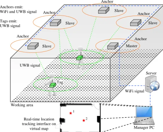
In this study, UWB based signal generating sensors are used which are low power and accuracy location estimation. There are tags and anchors in the RTLS structure. UWB is used in the tags; UWB and Wi-Fi wireless network communication architecture are used in the anchors. The short UWB signal sent by the tags is received by anchors. Each slave anchor, after calculating the distance traveled by the tag, it transmits it to the main anchor using the Wi-Fi infrastructure. Then the master anchor sends all the data to the server via Wi-Fi. Thanks to the improved
accuracy positioning control algorithm, the distance to tag from anchor is calculated using at least three anchor data. The manager or administrator traces the target in real time with a RTLS interface, which is a virtual map of the work area. In the same way, using tags and anchors, emergency information is transmitted between the target and the manager to create a structure that gives timely warning. Thus, a RTLS structure is established that can operate in both open and closed areas. Architecture of RTLS used in this study is given in Figure 1.
WiFi signal Anchor
Server Anchors emit:
WiFi and UWB signal Tags emit: UWB signal UWB signal Anchor Anchor Anchor Anchor Master 2 1 Real-time location tracking interface on
virtual map Manager PC
Working area Tag 1 2 Slave Slave Slave Slave
Figure 1. Architecture of real-time location system.
3. Accuracy positioning control algorithm
The mathematical algorithm to be used for accuracy location estimation in RTLS is very important for accuracy. In this paper, a unique accuracy positioning control algorithm has been developed to determine a precise location. This algorithm estimates the location with the data received using at least three anchors. This is why the intersection points of the anchors are important. There should be no blind point between the coverage of anchors. Therefore, the distance between each anchor should be 20-30 m depending on the working area to be installed. This limit is the communication distance of the DWM1000 location sensor module. This distance value should not be exceeded to get good quality and interference-free data.
When measuring the distance with 3 anchors, it appears that each of them generates areas of
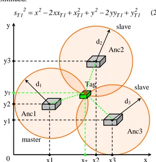
intersection of diameters. When a tag is placed in an area with a known distance between the anchors, the accuracy location can be determined by calculating the distances of the tag to the anchors. Figure 2 shows the positioning method between the anchors and tags required for the accuracy positioning control algorithm. Some calculations are made according to the accuracy positioning control algorithm to calculate the position of tag as in Figure 2. The target of tag to be traced will be expressed by T and its position in the x-y coordinate system will be determined. More than one anchor can be found on the same coordinate system. The distance between target tag T1 and anchor is given by Eq. (1).
(
) (
)
2 1 T 2 1 T 1 T x x y y s = − + − (1)In Eq. (1), sT1 is the distance between tag and anchor.
xT1 and yT1 are the position of T1 on the space coordinate system. Eq. (2) is obtained when Eq. (1) is
continued. 2 1 T 1 T 2 2 1 T 1 T 2 2 1 T x 2xx x y 2yy y s = − + + − + (2) Anc1 Anc2 Anc3 Tag d1 d2 d3 master slave slave y x x1 xT x2 x3 y1 y2 y3 yT 0
Figure 2. The positioning method between anchors and tags. In order to convert an equation containing x2 and y2 to a linear equation, it is necessary to subtract sT21 from
2 n
s as in Eq. (3). The s is the new position value of n2 the anchor that changes over time. In order to simplify the square expression in the Eq. (2) and to determine the tag that changed the position in time, the Eq. (3) is written.
(
)
2 n 2 1 T n 1 T 2 n 2 1 T s 2x x x x s − =− − + −(
)
2 n 2 1 T n 1 T y y y y y 2 − + − − (3)A linear series of equations are generated for determining the tag location. These linear equation solutions especially enable processors to perform fast processing at the computational stages. Eq. (3) is written in matrix form as in Eq. (4) for convenience in processors. Since a lot of samples are received over time, it is written in Eq. (4) to more easily calculate these values to the processor.
= y x K m (4)
The matrix of Eq. (4) is written in detail as in Eq. (5).
+ + − − − + + − − − + + − − − = − − − n2 2 n 2 n 2 1 n 2 1 n 2 1 n 2 n 2 n 2 n 2 2 2 2 2 2 2 n 2 n 2 n 2 1 2 1 2 1 y x s y x s y x s y x s y x s y x s m (5)
The matrix K is given in Eq. (6).
− − − − − − − = − −1 n n 1 n n n 2 n 2 n 1 n 1 y y x x y y x x y y x x 2 K (6)
If there are 3 anchors in the RTLS as in Figure 4, n=3.
The location of tag to be traced T is calculated by Eq. (7).
m K
T= −1 (7) If there are more than 3 anchors in RTLS, the unknown number in the equation will increase. However, it will be ensured that the target is more sensitive to the determination of T location. Eq. (8) gives the equation of T location calculation when there are more than 3 anchors.
( )
K K K mT = T −1 T (8)
KT takes the transpose form of the K matrix.
The estimation model developed for accuracy positioning control algorithm finds the target location with the smallest error. During the anchors measurements with tag, although the working area is ideal, sometimes there can be some noise. This problem can be overcome by bringing exactly intersecting areas, especially with anchors. Also the distance data collected by the anchors is reduced by the Kalman filter. The proposed algorithm collects data at intervals of 100 milliseconds. After each of the collected data is filtered, accuracy position calculation is performed for each. After the mathematical operations given in the study, every 100 millisecond position is recorded in the registers. Then, these position values are compared and high error rate data is filtered. Thus, by using an accuracy positioning control algorithm, a RTLS is created providing fast, accuracy and timely warnings and a new approach is taken by the studies in RTLS area. The flowchart of the accuracy positioning control algorithm is given in Figure 3.
Determine x, y the coordinates of Tag Accuracy positioning control algorithm and
calculation Is signal received from
Tag? Install constant values and system diagnostic
Yes Start
Display Tag in virtual working map area
END Store data No
Kalman Filter data
Distance measurement of Tag with and Anchor
Data send to Server
Figure 3. Flowchart of accuracy positioning control algorithm in RTLS.
4. Experimental RTLS setup and study result
The UWB based DWM1000 location sensor module produced by Decawave was used in the tags in RTLS. This sensor is compliant for the IEEE 802.15.4-2011 standard which supports multiple data transfer in high
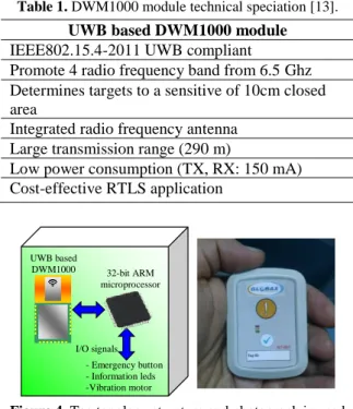
and low band. DWM1000 with low power consumption can be performed data transfer at 110 kbps, 850 kbps and 6.8 Mbps. Table 1 is given details the characteristics of the UWB based DWM1000 location sensor module [13]. This location sensor with integrated antenna, which can reduce the noise sources can accuracy determine the location. In addition, each tag uses 32-bit ARM core processors (Atmel SAM3X8E ARM Cortex-M3) which performs data transfer operations and controls. The tag topology structure and photograph used in RTLS are given in Figure 4.
Table 1. DWM1000 module technical speciation [13].
UWB based DWM1000 module
IEEE802.15.4-2011 UWB compliant
Promote 4 radio frequency band from 6.5 Ghz Determines targets to a sensitive of 10cm closed area
Integrated radio frequency antenna Large transmission range (290 m)
Low power consumption (TX, RX: 150 mA) Cost-effective RTLS application - Emergency button - Information leds -Vibration motor UWB based DWM1000 I/O signals 32-bit ARM microprocessor
Figure 4. Tag topology structure and photograph in used RTLS.
The anchors in RTLS also include both UWB based DWM1000 location sensor module and Wi-Fi module. The ESP-12 Wi-Fi module is used as the Wi-Fi communication network. This ESP-12 Wi-Fi module is very suitable for use in RTLS thanks to its low power consumption and compact dimensions. It is also becoming more affordable for anchor networks to be installed in large working areas. As with the tags, 32-bit ARM core based processors are used in anchors. After the distance of the tags is measured, the wireless network technology transfers the data to the master Wi-Fi very quickly and the necessary data is sent for the accuracy positioning control algorithm. Depending on the working area, it is necessary to be 20-30 m between the anchors in order to be able to make accuracy location tracing. Through the wireless network infrastructure to be created, it is possible to trace a target in the ratio of mm-cm sensitivity. The anchor topology structure and photograph used in RTLS are given in Figure 5.
UWB based DWM1000 I/O signals - Caution led - Information leds - Alarm 32-bit ARM microprocessor Wi-Fi based ESP-12
Figure 5. Anchor topology structure and photograph in used RTLS.
RTLS performance has been studied by performing worker tracing on a sample construction working area. The designed tags were produced as a wearable device so as not to interrupt the working program of the worker's construction area. Thus, both the worker is fulfilling occupational health and safety, and the position of the worker can be monitored in real time. In figure 6 is given a photograph of the worker tracing application in the construction working area where RTLS is installed. Here, tags and anchors are placed in the working area between 10 m and 15 m intervals. The system is then operated via the UWB network. Data were collected in a single center via server using Wi-fi infrastructure. The manager follows this data in detail on the virtual map.
Figure 6. RTLS application in working area. Figure 7 shows the values of the tag position in the x and y coordinates, which are received 100 ms frequently during RTLS application. Accuracy location algorithm allows the tag location to be measured with an error of approximately 10-20 cm.
1800 msec x and y values
cm
In the implemented RTLS study, accuracy positioning control algorithm is used to determine the target location and send it to the server over the wireless network. The location of worker with data sent to server is presented in real time on the previously prepared virtual map to the manager. Real-time location tracking interface on virtual map is given in Figure 8. In addition to monitoring RTLS, it also
ensures bidirectional communication support, thus providing a timely alert infrastructure. The low power consumption of RTLS effectively supports the use of these technologies. Moreover, thanks to this wearable technology, which can be easily placed inside the helmets, it has been given a different dimension to occupational health and safety, work quality and productivity. Real-time location tracking interface on virtual map x xT y yT 15m 12m 12m 8m 10m 6m 0
Figure 8. Real-time location tracking interface on virtual map, PC of manager.
5. Conclusion
Recently, with the increase of wearable technologies, many innovations have emerged in the area of accuracy positioning studies. In this study, an accuracy positioning sensor was used to examination that could be used especially in the area of occupational health and safety. The location of the target to be tracked by the developed accuracy positioning control algorithm is monitored in real time. This algorithm also reduces the computation time on the processor by means of fast processing, thus allowing the target to be tracked more frequently and accurately. This study also provided bidirectional data transfer between the worker and the manager by providing quick feedback which is one of the vital issues in terms of occupational health and safety. A wireless infrastructure was created with UWB based DWM1000 location sensor module and Wi-Fi based ESP-12 module. Thanks to wireless architecture, RTLS can be installed easily and stable, fast and accurate data transfer can be realized. In addition, a virtual map of the working area has been created with the RTLS interface developed for the manager. The location of the target is monitored in real time on the virtual map and in case of emergency, the target is quickly reached and the warning sensors in the area are used to make audible and illuminated notification to the surrounding area. A new perspective has been introduced in the accuracy location estimation with this RTLS study.
In this paper, the worker position was monitored at
intervals of 100 ms and the location was traced with a sensitivity of approximately 10-20 cm. In future works, camera can be added to this RTLS to provide real-time monitoring of the working area. Thus, it is possible to lead the working ergonomics by observing the working movements of the workers.
Acknowledgment
This study was supported by within Globax Technology Group company.
References
[1] Li, H., Yang, X., Wang, F., Rose, T., Chan, G., & Dong, S. (2016). Stochastic state sequence model to predict construction site safety states through Real-Time Location Systems. Safety Science, 84(1), 78-87.
[2] Donga, S., Lib, H., & Yinb, Q. (2018). Building information modeling in combination with real time location systems and sensors for safety performance enhancement. Safety Science, 102(1), 226-237. [3] Willa, M.K., Büttner, K., Kaufholz, T.,
Müller-Graf, C., Selhorst, T., & Krietera, J. (2017). Accuracy of a real-time location system in static positions under practical conditions: Prospects to track group-housed sows. Computers and Electronics in Agriculture, 142(1), 473–484.
[4] Sunderman, C., & Waynert, J. (2012). An Overview of Underground Coal Miner Electronic Tracking System Technologies. IEEE Industry
Applications Society Annual Meeting, Las Vegas,
[5] Fisher, J.A., & Monahan, T. (2012). Evaluation of real-time location systems in their hospital contexts.
International Journal of Medical Informatics,
81(10), 705-712.
[6] Budak, A., & Ustundag, A. (2015). Fuzzy decision making model for selection of real time location systems. Applied Soft Computing, 36(1), 177-184. [7] Huanga, S., Guo, Y., Zha, S., Wang, F., & Fang,
W. (2017). A real-time location system based on RFID and UWB for digital manufacturing workshop. Procedia CIRP, 63(1), 132-137. [8] Jobes, C., Carr, J., DuCarme, J., & Patts J. (2011).
Determining Proximity Warning and Action Zones for a Magnetic Proximity Detection System. IEEE
Industry Applications Society Annual Meeting,
Orlando, USA, 1-7.
[9] Rashid, K.M., & Datta, S. (2017). Coupling Risk Attitude and Motion Data Mining In A Preemtive Construction Safety Framework. Winter Simulation
Conference (WSC), Las Vegas, USA, 2413-2424.
[10] Huang, C.H., Lee, L.H., Ho, C.C., Wu, L.L., & Lai, Z.H. (2015). Real-Time RFID Indoor Positioning System Based on Kalman-Filter Drift Removal and Heron-Bilateration Location Estimation. IEEE
Transactions on Instrumentation and Measurement,
64(3), 728-739.
[11] Xiong, T., Liu, J., Yang, Y., Tan, X., Min H. (2010). Design and Implementation of a Passive UHF RFID-Based Real Time Location System.
Automation and Test Proceedings of 2010 International Symposium on VLSI Design, Hsin
Chu, Taiwan, 95-98.
[12] Sarrafan, K., Muttaqi, K.M., Sutanto, D., & Town, G.E. (2017). An Intelligent Driver Alerting System for Real-Time Range Indicator Embedded in Electric Vehicles. IEEE Transactions on Industry
Applications, 53(3), 1751-1760.
[13] Decawave. (2018). DWM100 Module. Available at:
https://www.decawave.com/products/dwm1000-module, Accessed 18 July 2018.
Ahmet Aktas received his B.Sc. in Electrical Education
from Kocaeli University in 2010. He received the M.Sc. degree from department of Energy Systems Engineering, Kocaeli University in 2013. Finally, he got his PhD in Energy Systems Engineering at Kocaeli University in 2016. He has published many papers in different subjects including multilevel inverters, photovoltaic power generation systems, renewable energy sources, energy storage technologies, battery and ultra-capacitor modeling, smart energy management, microcontroller programming, smart grid integration, microprocessor-based application systems, offshore wind turbine and flow energy. He is a member of IEEE and a reviewer at the IEEE Transactions on Sustainable Energy and IEEE Transitions on Energy Conversion magazine. He designs custom cards for military vehicles in the defense industry. He is listed in Editorial Team of the International Journal of Electric Power Science Development. He is currently a Department of Electrical and Electronics Engineering, Kutahya Dumlupinar University.
An International Journal of Optimization and Control: Theories & Applications (http://ijocta.balikesir.edu.tr)
This work is licensed under a Creative Commons Attribution 4.0 International License. The authors retain ownership of the copyright for their article, but they allow anyone to download, reuse, reprint, modify, distribute, and/or copy articles in IJOCTA, so long as the original authors and source are credited. To see the complete license contents, please visit