For Permissions, please email: [email protected]
Advance Access publication on 1 March 2017 doi:10.1093/comjnl/bxx020
Energy Ef
ficient IP-Connectivity with
IEEE 802.11 for Home M2M
Networks
I
HSANM
ERTO
ZCELIK1, I
BRAHIMK
ORPEOGLU1*ANDA
SHOKA
GRAWALA2 1Department of Computer Engineering, Bilkent University, 06800 Ankara, Turkey 2
Department of Computer Science, University of Maryland, College Park, MD 20742, USA *Corresponding author: [email protected]
Machine-to-machine communication (M2M) technology enables large-scale device communication and networking, including home devices and appliances. A critical issue for home M2M networks is how to efficiently integrate existing home consumer devices and appliances into an IP-based wireless M2M network with least modifications. Due to its popularity and widespread use in closed spaces, Wi-Fi is a good alternative as a wireless technology to enable M2M networking for home devices. This paper addresses the energy-efficient integration of home appliances into a Wi-Fi- and IP-based home M2M network. Toward this goal, we first propose an integration architecture that requires least modifications to existing components. Then, we propose a novel long-term sleep scheduling algorithm to be applied with the existing 802.11 power save mode. The proposed scheme utilizes the multicast DNS protocol to maintain device and service availability when devices go into deep sleep mode. We prototyped our proposed architecture and algorithm to build a M2M network testbed of home appliances. We performed various experiments on this testbed to evaluate the operation and energy savings of our proposal. We also did simulation experiments for larger scale scenarios. As a result of our test-bed and simulation experiments, we observed significant energy savings compared
to alternatives while also ensuring device and service availability.
Keywords: home M2M networks; internet of things; smart appliances; energy saving; IEEE 802.11; embedded IP networking; service availability
Received 19 June 2016; revised 24 November 2016; editorial decision 30 January 2017 Handling editor: Alan Marshall
1. INTRODUCTION
Tremendous growth and advances in device and communication technologies have enabled the development of a new networking paradigm, machine-to-machine (M2M) communications, which has recently received considerable attention. It is estimated that over 50 billion of these devices will be connected to the Internet by 2020 [1]. With the rapid penetration of embedded devices in home and business surroundings, it is envisioned that networks will shift from the current human-to-machine communications to a machine-to-machine paradigm. This shift requires the easy andflexible attachment of devices to the Internet, a high capabil-ity for autonomous registration and discovery of devices and low-power operation to enable green IT. However, the integra-tion of a huge number of devices and machines into existing IT systems in a cost-effective, energy-efficient and automated manner is still an open research issue. The same issue applies
to home M2M networks, where appliances and devices would be connected to each other and the Internet to enable various M2M applications.
There are various use-cases and applications for home M2M networks, some of which include controlling and moni-toring household appliances and lighting systems remotely, smart grids and energy management. For example, users can be notified via their smart TVs or smart watches when a washerfinishes its washing cycle. As another example, com-munication between the electricity grid and home M2M net-works can enable homeowners to automatically shift energy use to periods of low-cost electricity.
Existing IT systems with a wired Ethernet-like or wireless ZigBee-based distribution network are either inflexible, costly or require additional special gateways to connect machines
and devices to the Internet. Additionally, the usage charges for existing cellular networks and their services are expensive for the end users for continuous usage [2,3], which is typical in home M2M scenarios. Instead, using an existing Wi-Fi net-work infrastructure in implementing and deploying an embed-ded device network can save a lot of hardware costs, since Wi-Fi is already available and widely used in daily life, espe-cially in homes and offices. Therefore, Wi-Fi is a very attractive solution for the remote transmission and wireless monitoring needs of embedded devices in smart home and office systems. On the other hand, Wi-Fi consumes more power compared to other wireless technology alternatives like ZigBee or Bluetooth [4,5].
In this paper, we investigate the use of Wi-Fi technology and existing Wi-Fi infrastructure in connecting home consumer electronic devices, appliances and machines to each other and the Internet. Wefirst propose a way of integrating Wi-Fi tech-nology into home-embedded devices in an easy, modular, flex-ible and energy-efficient manner. To provide energy-efficiency, the IEEE 802.11 standard already has a Power Saving Mode (PSM). We analyze the impact of the standard IEEE 802.11 PSM on energy savings in a home M2M setting. Then, we pro-pose a longer term sleep scheduling algorithm, that can be used alone or on top of the standard IEEE 802.11 PSM, to further reduce the energy consumption in a home M2M network. Our proposed sleep schedule scheme favors energy-constrained devices by forcing the M2M devices to go into sleep mode depending on their available energy and power consumption profile. This method provides better compliance with tight standby energy regulations and significantly increases the life-time of battery-powered devices. Applying long sleep periods can greatly reduce energy consumption, but it can also cause loss of service availability when devices are in sleep mode. Our scheme also considers this and ensures service discovery and availability despite sleep scheduling. Additionally, our scheme does not require any changes to the standard 802.11 MAC and PSM protocols, since such changes would reduce the rapid and widespread deployment of the proposed scheme.
We prototyped our proposed architecture and algorithm to build an M2M network test bed consisting of home appliances. We then performed experiments on this testbed for measuring the energy consumption of Wi-Fi modules to evaluate the per-formance of our proposed sleep scheduling approach. To evaluate the proposed approach also with a large number of stations, we conducted simulation experiments using real energy consumption data from the test-bed experiments. The results showed that the proposed sleep scheduling scheme achieves energy conservation of up to 71% compared to the existing infrastructure, which applies no sleep mechanism, and up to 20% compared to the standard 802.11 PSM scheme, while at the same time keeping device and service availabil-ity. Furthermore, our prototype implementation on the home appliances also validates the argument that the proposed scheme is feasible for real-life deployment.
The remainder of the paper is organized as follows: related work is presented in Section2. Section 3describes the pro-posed system architecture and how we can integrate a home machine in a Wi-Fi network and make it part of the Internet to enable M2M applications. Section4presents our proposed sleep scheduling scheme on top of the IEEE 802.11 PSM. Finally, we present and discuss our experimental results in Section5and conclude the paper in Section6.
2. RELATED WORK AND BACKGROUND 2.1. Related work
Numerous studies have been conducted on home M2M com-munication, from system architectural challenges concerning real-life practicality to various system integration models and energy efficiency in wireless communication.
Architectural challenges in home M2M networks are explained in [3, 6–8]. These studies commonly point out two difficulties in the deployment of M2M networks: an essential need for low energy consumption in communica-tion, and the requirement for intermediate protocol transla-tion gateways. The argument about the practicality of such gateways is supported in [9], indicating that how to connect non-IP-based M2M components to the existing Internet back-bone is still an open issue. In [6], various M2M radio technolo-gies such as ZigBee, Bluetooth Low Energy and Wi-Fi are compared and the authors conclude that Wi-Fi is the most accepted protocol for wireless communication in homes and that it eliminates the requirement of protocol translation gate-ways due to being IP-enabled, although it requires more power than other alternatives. Ref. [6] also states that it is important to manage home networks so that resource-constrained home devices use their energy efficiently. Different M2M radio tech-nologies are investigated in [10], and again the high energy consumption of Wi-Fi is noted as a crucial drawback of this system for home M2M networks. Ref. [7] also emphasizes need for low power consumption of the radio as an important characteristic of home M2M networks. In a similar manner, [3] underlines energy-efficiency and cost-effectiveness as M2M design challenges. Ref. [8] draws attention to the necessity of using low-power consuming technologies in home M2M net-works while explaining the crucial role of M2M communica-tions in home automation. Ref. [8] also highlights the trade-off between power consumption and device reachability by argu-ing that longer sleep cycles obviously provide power savargu-ing efficiency despite negatively affecting device availability. To keep a balance between energy efficiency and device reachabil-ity, our proposed approach maintains device availability even for devices in deep sleep mode.
How to integrate Wi-Fi technology into embedded devices in homes is illustrated in [11,12]. The authors of these stud-ies propose a system model to provide wireless monitoring and remote control for embedded devices by gaining IP
connectivity. Similarly, in [13], a home monitoring system based on Wi-Fi and sensor technologies is implemented with a detailed software and hardware architecture. The high power consumption of their models is a critical problem for real-life deployment, and there is no procedure for reducing it. Ref. [14] proposes a Wi-Fi sensor mote for wireless embedded Internet applications with a prototype implementa-tion. In [14], although the proposed low-power hardware architecture gains power savings, downlink packet delays and device reachability during sleep periods are not considered. How to configure such smart devices with no sophisticated input apparatus to connect a specific AP with a password spe-cified by the user is also an open issue in all of these studies. A system model for embedded webserver-based home appli-ance networks using the Ethernet is presented in [15] and is verified through a prototype working with real appliances. However, this model does not use radio communication and consequently is not very convenient. In addition to these stud-ies, there are many studies on M2M smart home systems that use a 3G infrastructure in the physical layer, but in our study, we do not consider cellular systems for home M2M networks due to their cost disadvantage.
To alleviate the high energy consumption of Wi-Fi, the 802.11 standard already defines a power save mode [16]. Basically, 802.11 PSM proposes a scheme to turn off stations while they are not actively communicating and to wake them up from the sleep state periodically to listen to traffic announce-ments. There are many 802.11 PSM-related studies aimed at minimizing energy consumption in M2M networks. We cat-egorize these studies into two groups: one requiring changes on the AP side [17,18] and the other about strategies on the client side [19–23]. In [20], DeepSleep is proposed for M2M net-works based on the IEEE 802.11 by giving higher priority to low-energy devices in channel allocation and putting them into sleep mode for longer periods of time. Ref. [23] defines a new intermediate PHY state to immediately switch off the receiver after the destination address is received. In this way, the pro-posed approach gains power savings by reducing overhearing. These strategies, however, require modifications to the standard 802.11 MAC and PHY protocols. Hence, deploy-ing such enhancements in a practical way is problematic since the MAC and PHY protocols are typically implemen-ted in hardware. Ref. [21] proposes traffic-aware duty cycles instead of fixed wake-up intervals. Similarly, [22] chooses an adaptive interval time for sleeping depending on the time of the session activity at the IP layer. Instead of these sleep scheduling-based power saving mechanisms, power control-based strategies can also be applied to conserve energy con-sumption in M2M networks. As an example of such strategies, [24] minimizes transmission energy of routes by selecting the forwarder node with the help of a stateless gradient-based forwarding protocol in a distributed manner. There are also studies focusing on localizations issues [25–27]. In this paper, we are concerned about home M2M applications
where precise locations of devices are not needed, hence we are not addressing localization problem and its effect on energy consumption.
2.2. Overview: IEEE 802.11 power save mode
The IEEE 802.11 has a PSM where devices turn off their transmitters to minimize power consumption when there is no active communication and wake up when there are data pack-ets to transmit or receive. The IEEE 802.11 standard supports the PSM as follows:
It can be operated in an infrastructure mode or an ad hoc mode. The detailed operations of the two modes are some-what different. This paper focuses on infrastructure-based M2M networks and therefore we describe the power saving mechanism in the infrastructure mode. We assume that in a home environment, there can be at least one wireless AP that can monitor the current mode of each associated sta-tion. Within the infrastructure mode, the 802.11 PSM sup-ports two modes: active and power saving. Compared with the PSM, a station in active mode is fully powered and con-sequently may send and receive packets at any time, but consumes much more energy.
On the other side of the spectrum, a station in PSM only wakes up periodically to check whether there are any incoming packets from the AP. The station always notifies its AP when switching modes. The home AP periodically sends beacons spaced by a static beacon interval (BI). A station in PSM should monitor these frames. Once every BI, the AP transmits a beacon frame containing a traffic indication map, which con-tains the identifiers (IDs) of those stations in PSM for which there are buffered unicast packets waiting in the AP. Upon hearing its ID, a station in PSM should stay awake for the remaining BI to receive packets destined to it.
The power saving mechanism in the ad hoc mode, where timing synchronization as well as packet storing and forward-ing must be done in a distributed manner, and is more com-plicated. Details for ad hoc networks can be found in [16].
2.3. Overview: multicast domain name service
After joining a home M2M network, appliances need to be accessible to and usable by each other and other users through well-defined interfaces. They need to be seamlessly integrated into the home M2M network. These necessities can be achieved if the appliances can announce their services and if they can discover each other’s services. To enable ser-vice discovery in a local area network (LAN), Multicast domain name service (mDNS) is specified by the IETF Zeroconf initiative as an application layer protocol [28]. We use the mDNS to enable an appliance to discover other appli-ances and their services in a home M2M network.
The mDNS provides DNS operations on a local link with-out a conventional unicast DNS server. The major difference between mDNS and the conventional DNS is that the client transmits its DNS query message to a multicast address on the LAN instead of sending to a DNS server. Then, all target devices with the mDNS server can hear the multicast query message and respond with a packet that consists of their ser-vices and IP addresses. Similar to the conventional DNS, mDNS uses UDP packets based on the normal DNS packet format. The mDNS protocol uses the multicast IPv4 address 224.0.0.251 and the UDP port number 5353.
The mDNS specification has two popular implementa-tions, Apple Bonjour [29] and Linux nss-mdns services. These implementations are not very practical for home appliances due to their memory space requirements; there-fore, in this paper, we adapted Broadcom’s Gedday library as a lightweight and memory-efficient implementation of the mDNS protocol to run on top of any real-time operating sys-tem. Additionally, we developed a custom mDNS test soft-ware to monitor all devices and their services in a home M2M network.
3. PROPOSED INTEGRATION AND SYSTEM ARCHITECTURE
Wireless USB dongles are prevalently used in smart TVs, PCs and laptops. However, embedded devices used in home appliances, industrial instruments, intelligent actua-tors, smart sensors, etc., generally do not have a USB inter-face or need complex USB driving programs to use a wireless USB dongle. Therefore, use of standard wireless USB dongles is not very practical for embedded devices to enable M2M communication.
To enable wireless access for home appliances for M2M communication, we propose and implement the system archi-tecture shown in Fig. 1. Normally, the existing home-embedded devices are powered by one or more main process-ing cores, typically either micro-controllers or digital signal processors (DSPs). Washers, dryers, ovens, set-top-boxes, air conditioners, digital cameras, intelligent instruments, etc., exemplify this architecture. Since the micro-controllers or DSP boards in these devices usually include a serial commu-nication interface, embedded devices can easily be integrated with Wi-Fi using our proposed architecture in Fig.1.
In our architecture, an embedded device communicates with a separate Wi-Fi module via a serial communication interface (e.g. a UART). Simply, the Wi-Fi module can be thought of as a UART-to-wireless converter. It has two main parts: a Wi-Fi chipset (radio transmitter) and a Host micro-controller unit (MCU) (processor) running the necessary sys-tem software and communication protocols. The Wi-Fi chipset provides wireless last-hop connectivity to an access point. The MCU runs the necessary software to control the
wireless module and to enable its communication with the locally connected home appliance (via serial port) and also with other home appliances (via IP enabled M2M network).
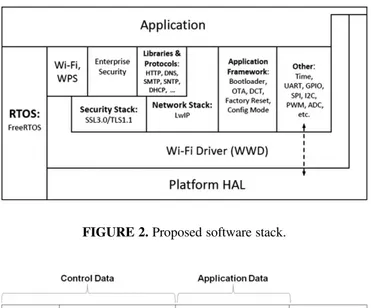
The proposed software system for the wireless module con-sists of RTOS, TCP/IP Stack and IP communication functions, Wi-Fi functions, Platform functions, Serial communication functions and Authentication functions. In our implementation, Free RTOS [30] is used to serve real-time application requests, which basically provides thread, semaphore, mutex and timer management functions. To implement IP communication toward the other M2M appliances, we use lightweight TCP/IP (lwIP), which is appropriate for embedded systems with tens of kilobytes of RAM [31]. Finally, Platform functions in the proposed stack allow managing hardware components such as UART, SPI, I2C, GPIO and Watchdog Timer. Figure2shows the software system used on our the integration architecture illustrated in Fig. 1. The different layers can be distributed over different physical tiers.
We designed a device-specific communication protocol to run over the serial interface connecting the Wi-Fi module to the embedded device. The frame format of a packet crossing the interface is shown in Fig. 3. It consists of two parts: the control and the application data. The control part includes fields to enable an embedded device to control the Wi-Fi
module; for example, to open/close the Wi-Fi antenna and switch between a Software-enabled AP (Soft AP) mode and a station (STA) mode, which is explained later. This part also includes a device ID, which allows the Wi-Fi module to learn about the appliance the embedded device is controlling. The application data part refers to device-specific data and is defined by the user application. It is the raw application data between a user terminal (e.g. a smart phone) and the embed-ded device. For instance, oven temperature is carried a part of the application data.
For authentication of a home appliance to a wireless AP, we modify the existing Wi-Fi authentication architecture since it is hard to directly apply to home appliances with no sophisticated input device. Before sending and receiving data in the home network, a Wi-Fi-enabled embedded device needs to connect to an AP in the home, which has a specific SSID and password. Since embedded devices usually do not have an input/output such as a terminal apparatus or a GUI interface, setting up authentication information on the embedded device to connect it to a specific home wireless LAN (WLAN) is not trivial. As part of our solution to this problem, we benefit from Soft AP mode and an embedded HTTP web server running on the Wi-Fi module to configure an embedded device to connect to a specific home WLAN. The Soft AP can be enabled on a Wi-Fi module to make an AP and a hotspot for a time. To secure the proposed con fig-uration process, the Soft AP has a WPA security key in an embedded device with a display of at least eight characters. A user can connect to the embedded device’s Soft AP and send the home WLAN SSID and password to the Wi-Fi mod-ule via the embedded HTTP server running on the modmod-ule.
Then the Wi-Fi module integrated in embedded device switches to STA mode and connects to the home WLAN.
Alternatively, the Wi-Fi Protected Setup (WPS) could be applied to enter a wireless AP SSID and password into an embedded device. In the WPS, Push Button Configuration (PBC) method [32], users start the configuration procedure by pressing buttons on both the AP and the client device. Using the WPS PBC to add an embedded device to a wireless home network without entering long pass-phrases seems easy in terms of user experience. However, the WPS has a security flaw that allows brute force attacks [33]. Additionally, another security concern arises with neighbor home networks: embed-ded device can be accidentally connected to a WPS-enabled wireless network in a neighboring home. For these reasons, we prefer to use Soft AP and an embedded HTTP server on the Wi-Fi module instead of using WPS PBC.
We prototyped the proposed architecture for a home M2M network consisting of a smart tablet and home appliances such as a washer, dryer, oven, dishwasher and fridge. All Wi-Fi modules integrated in the appliances have the same generic software. An integrated Wi-Fi module communicates with the respective appliance over the UART and with a remote tablet application over the wireless and Internet sys-tems. A Wi-Fi module periodically polls and reads the frames that might be coming from the embedded device via the UART interface. If there is any state change in the appliance, the change is indicated by generating and sending a data packet from the appliance. For instance, if the washing state inside the washer is updated, the washer indicates the new state in the respective field of a new data frame created. Then, the data are sent by the Wi-Fi module to a remote application running on the smart tablet by use of TCP sock-ets. The application can interpret the data and update its GUI. The data/control flow can go in the other direction as well: from the tablet application to the appliance.
Figure 4 illustrates the overall network architecture and use-case scenario, in which there are monitoring and control applications running on smart phones or tablets. The appli-ances are intelligent instruments or have smart sensors that communicate with those monitoring and control applications via Wi-Fi modules.
In this manner, the appliances form a Wi-Fi WLAN. Using wireless communication for applications eliminates complicated wiring. All appliances in the WLAN are con-nected to a wireless AP, which enables communication among appliances and also between appliances and a wired network. The wired network can be a wired LAN (Ethernet) or a WAN. The connection technology of the AP to the WAN and the rest of Internet can be PSTN, ADSL, DDN, Fiber or 3G. In this manner, multiple Wi-Fi-enabled home appliances can form an M2M network spanning both wireless and wired LAN/WAN networks. Then, a local or remote mon-itoring and control application can access the appliances via this M2M network.
FIGURE 3.Data frame format in the communication between appli-ance and Wi-Fi module.
FIGURE 2.Proposed software stack.
4. PROPOSED LONG-TERM SLEEP SCHEDULING SCHEME
In this section, we describe our long-term sleep scheduling scheme proposed to reduce the energy consumption of home-embedded devices connected to a Wi-Fi-based M2M network without losing service availability. Sleep scheduling (or duty cycling) is an effective way to reduce energy consumption in distributed systems and networks [34,35]. It consists of put-ting some devices (i.e. their Wi-Fi wireless modules) into sleep state and alternating between sleep and active states. Most distributed solutions so far aim to ensure coverage while performing sleep scheduling [36, 37], however, virtu-ally no work considers ensuring device and service availabil-ity while doing sleep scheduling.
Our proposed scheme guarantees that at any time at least one station in the home M2M network is in an active (awake) state. The active station also broadcasts mDNS replies on behalf of stations in a sleep state. In this way, we maintain service discovery and availability for all M2M-connected devices. A monitoring center application, for example, which scans all connected-embedded devices and their offered ser-vices, can list all devices even though some of them may be in sleep mode.
Let us consider a set of appliances as stations S= {STA , STA ,1 2¼, STAN}connected to a wireless AP. A sta-tion switches between three states: Sleep, Active and Announce. Additionally, we assume that all stations are time synchronized.
The sleeping scheme operates in cycles and in each cycle it puts one device into active state and other devices into sleep state. Cycle is the unit of time in our scheme. Device states can be updated and changed in the beginning of each cycle. The cycle length is a network-wide parameter and needs to be set at the network configuration and initialization phase. The time interval during which each device is put into the active
state once is called a round. One round consists of multiple cycles. The round duration depends on the number of devices and for how many cycles each device stays active continu-ously. For an example, if there are N devices and each device is active for only one cycle, then the round duration is N cycles.
Our sleep scheduling scheme utilizes the mDNS query and response packets. All mDNS queries are sent using a service name. The specific service name we use is homeM2M.local. We use the Rdata field of the response packets to convey information about stations and their sleep-scheduling-related parameters. The format of an mDNS packet and how we use it to convey the information required by our protocol is shown in Fig. 5. Each mDNS response packet includes algorithm-related flags, current cycle number, number of devices and information about all devices in the network. The flag field is one byte long and the least significant bit is used to indicate an abnormality condition, which is set in case of a crash. Other bits in the flag field are reserved. The current cycle number is regularly incremented by one for each cycle. The remaining part of the frame consists of description infor-mation for all n devices in the network, represented for each device with four bytes: one is for the device identifier (ID), one for the activeness factor of the device (k), which will be explained soon, and the other two for device type. Device IDs are incrementally distributed as shown in the ANNOUNCE
algorithm in Fig.7.
The main state diagram of our sleep scheduling scheme is given in Fig.6. When a new device initially joins a network, it is in Announce state and starts running the ANNOUNCE
algo-rithm (shown in Fig.7). According to this algorithm, the new device sends an mDNS query packet to the network and waits for responses. If there is no response, it means there is no other device in the network except the new one. In this case, the new device just runs the standard IEEE 802.11 PSM. Otherwise, the new device discovers and learns about the existing devices and which one is the active device through the mDNS response packets received from them. From the active device, the new device also retrieves the current para-meters of the sleep-scheduling scheme, which are the current
FIGURE 5.Rdata frame that conveys all sleep-scheduling related-parameters encapsulated in the mDNS response packet.
cycle number, the number of devices in the network and information about other devices in the network (their types and power consumption profiles). To check whether a new device is added or not, the active device sends an mDNS query to the network just before it goes into Sleep state.
Then, the new device informs the active device about itself by sending an mDNS reply packet.
We propose the use of an activeness factor parameter (k) in our sleeping scheme. Each device will have an activeness fac-tor that will reflect how much relative power consumption the device can tolerate in the Wi-Fi module. The factor is related to the power the device operates on and how the device obtains its energy. This method helps balancing the sleep per-iods among different energy-level devices. If this factor is higher for a device, the device tolerates more power con-sumption in the Wi-Fi module. Otherwise, if this factor is low, the device does not tolerate much power consumption for wireless communication in the Wi-Fi module. For example, a battery-powered device will have a small active-ness factor. As another example, a 1000 W appliance will have a larger activeness factor compared to a 50 W appliance, even though both of them are mains-powered. Country limits for home appliance standby electric power consumption affect the activeness factor parameter (k). In Europe, for example, these limits are defined by EU regulations [38]. The limit for ovens is 1W while the limit for coffee machines is 0.5 W. That is, ovens can tolerate more energy consumption than coffee machines. Hence, the possible activeness factor parameter (k) for ovens in the EU can be 2, for example, while it can be 1 for coffee machines.
We assume that the Wi-Fi module integrated with an appli-ance can learn the type of the device over the serial communi-cation port at power-up and assign itself an activeness factor by matching the device type to a k value in a pre-configured table. This table can be statically embedded on all Wi-Fi modules and a kivalue in the table can be determined as
=ìíïï î ïï + êë úû ⌊ ⌋ k p p p p p , if is defined 1 , otherwise i i min i max min = { ¼ } = { ¼ } p p p p p p p p min , , , max , , , n n min 1 2 max 1 2
pi: limit of standby electric power consumption for STAi In our sleeping scheme, the period of time (in cycles) during which a device stays active in one round depends on its activeness factor. As the factor increases, the number of active cycles increases proportionally. Let kidenote the
activeness factor for the STAi. Using ki values of the
sta-tions, the total number of cycles in one round can be calcu-lated as in Equation 1. In a round, each STAiis active for
ki cycles. Then, the number of cycles ti before the active
state of a station STAi begins can be calculated with
Equation2.
At the beginning of each cycle, each device runs the algo-rithm UPDATESTATE(given in Fig.8) to decide its state in that
cycle using the current cycle number, station ID, and the Ttotal
procedure Announce(deviceT ype, k)
: activeness factor : id for ST Ai.
Query homeM 2M.local for mDNS announce-ments
n ← number of devices parsed from the query response
n ← n + 1 i ← n
if n == 1 then
Apply only the PSM
Start the conventional mDNS responder in homeM 2M.local
else
deviceInf o ← i + k + deviceT ype
modif iedRdata ← the response of the query + own deviceInf o
Start the mDNS responder with modif iedRdata in homeM 2M.local
end if end procedure
FIGURE 7.Announce algorithm.
FIGURE 6.State diagram for an individual device in a home M2M network.
and ti values, given in Equations 1 and 2. If the algorithm
returns TRUE, the state of the device will be Active. Otherwise, it goes into Sleep state by deactivating its WLAN interface. Each active device retrieves the details of the other devices in the home M2M network and the value of an abnormalityFlag from an active device in the previous cycle. An abnormalityflag indicates whether there was an abnormal condition detected in the previous cycle. When the active device cannot communicate with an active device from the previous cycle, it sets the abnormalityFlag to TRUE and remains active during the subsequent cycles until a stable state. That is, each device runs the algorithm RECOVERFAULT
shown in Fig. 9at the beginning of each cycle in case of a crash, and no sleep procedure is applied until all devices are active. After such a stable point, the parameters of the pro-posed sleep scheduling are reinitialized and the procedure is restarted:
å
= ( ) = # T k 1 j j total 1 deviceså
= ( ) = -ti k 2 j i j 1 1Figure10shows how to run the proposed scheduling algo-rithm in a home M2M network of four stations. In the example, the activeness factor of Station 2 (k2) is 3 and
the other stations have an activeness factor of 1. The example illustrates one round, which includes six cycles (i.e. Ttotal
is 6).
Our sleep scheduling scheme together with mDNS enables service discovery while efficiently utilizing energy. In the next section, we evaluate the energy performance of our scheme.
5. EXPERIMENTS AND EVALUATION
In this section, we present our experimental results to evalu-ate the energy consumption and efficiency of the standard 802.11 PSM and our sleep scheduling scheme. Wefirst per-formed experiments and measurements using our M2M testbed. We measured the energy consumption of the Wi-Fi modules using both the PSM and our sleeping scheme. Then, we evaluated our scheme for larger topologies using simula-tion experiments. We used the real energy consumpsimula-tion data from our test-bed experiments while calculating the energy consumption value in our simulation experiments.
5.1. Test-bed experiments
In our testbed, we used Broadcom’s WICED Development System’s Wi-Fi development module as the wireless M2M module, which consists of a BCM43362 Wi-Fi chip and an STM32F205 microprocessor. The power supply to the mod-ule is 3.3 V. The system is a low-power SOC with a built-in Wi-Fi protocol stack, which includes serial communication hardware and a serial driver interface [39]. As long as an embedded device (home appliance) has a serial communica-tion interface, the module can be integrated into it easily. It supports 802.11 b, g, n. It also supports TCP and UDP data transmission.
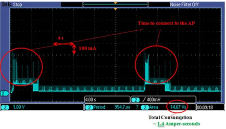
In our testbed, wefirst tested and verified the IEEE 802.11 standard PSM and then measured its energy efficiency. The experiment result is shown in Fig. 11, which is a 5-second
procedure
UpdateS-tate(cycleN o, i, ki, n, abnormalF )
: id for ST Ai. : expected number of devices
if abnormalF is TRUE then
For fault tolerance recoverFault(abnormalF , n);
returnTRUE end if
Ttotal← CYCLES-IN-A-ROUND
ti← CYCLES-BEFORE-DEVICE(i)
xi← (cycleNo mod Ttotal)− ti
if xi≥ 0 and xi< (ti+ ki) then returnTRUE else returnFALSE end if end procedure
FIGURE 8.State updating algorithm.
procedure RecoverFault(abnormalF, n)
Query for mDNS appliance announcements
ncurrentactive← number of responses to the query
if n == ncurrentactivethen
Set abnormalF to FALSE;
else
n ← ncurrentactive
end if end procedure
FIGURE 9.Fault-tolerance algorithm.
FIGURE 10.A sample scheduling of sleep states by the proposed algorithm for nodes in a home M2M network.
capture of electrical current consumed at the Wi-Fi module while running an embedded test application sending ICMP ping packets to a wireless AP at 1-second intervals. Ping packets simulate the data packets that can be carried in a home M2M network. We set the ping packet size to 64 bytes to mimic the data size in a typical M2M scenario, which is expected to be quite small. In Fig.11, the large blue spikes correspond to cur-rent consumption in the Wi-Fi module while transmitting ping packets. The smaller blue spikes occurring approximately every 300 ms correspond to the 70 mA current consumption used when the Wi-Fi is not transmitting but is awake to listens for DTIMs. The 300 ms intervals between two blue spikes is the sleep period between two active states in IEEE 802.11 PSM. During sleep, the chip consumes almost zero energy. The red spikes that occur at regular 100 ms intervals are the result of an IGMP timer in the network stack that wakes the STM32. This experiment shows the significant energy savings in PSM (70 mA without sleep versus nearly 0 mA with sleep).
We used the Maxim MAX4376 current-sense amplifier to measure the differential voltage across a0.2Wresistor in ser-ies with the module’s power supply. The output voltage of the circuit is scaled to produce 1 V for every 100 mA (or 10 V for every 1A) of current consumed. For example, when the Wi-Fi module consumes 500 mA, the circuit produces an output voltage of 5 V.
We then measured the effect of our proposed sleep sched-uling scheme on energy consumption. We prepared three different test setups with different configuration parameters. All setups have a wireless AP and multiple embedded devices (Wi-Fi modules) representing home appliances. The appliances connect and send ping packets to the AP. All appliances are assumed to have the same activeness factor k for these tests. In each test, the current consumption in a 40 s interval is measured and the total energy consumption is calculated by multiplying the power supply voltage (3.3 V) with the total area under the current-time curve.
Ourfirst test aims to observe the total energy consump-tion with no sleep periods. The appliances are connected to the home WLAN and neither the IEEE 802.11 PSM nor our sleep scheduling is applied. The wireless module is always active (idle listening or transmitting or receiving). In this test, the total energy consumption for an individual module during the experiment period (40 s) is measured to be 11.5 J.
Our second test is performed to calculate the total energy consumption when the PSM is used alone. In this experiment, the appliances arefirst associated to a home AP and the IEEE 802.11 PSM is activated. The Wi-Fi modules on the appli-ances periodically wake up to listen to the AP. The experi-ment lasts 40 s and at each 5 s interval the wireless module sends a ping packet to the AP. The total energy consumption is measured and calculated as in the previous test and for an individual device is measured to be around 5.3 Joules. We also observed that the reply time of ping packets is ∼0.5 s. This delay is caused by the trade-off between energy savings and packet delay. This measurement shows that the IEEE 802.11 PSM can provide∼54% energy savings with tolerable delays compared to not using sleep mode.
In our third test, our proposed sleep scheduling method is applied with the IEEE 802.11 PSM, which means that while the standard PSM applies short-term sleep schedul-ing, our method is applying long-term sleep scheduling at the same time, independent of PSM, and leaves only one device active to maintain continuous service availability in the M2M network. In this setup, we connected three appli-ances to the home AP and set the maximum sleep duration for a device to 20 s. As soon as an appliance connects to the AP, it informs the active device about itself. Then it deactivates its Wi-Fi interface and goes into long sleep until the next cycle. When a device is in long sleep, the active device in the network broadcasts mDNS messages on behalf of the sleeping device and stores the incoming messages destined to it. In this way, an M2M application scanning the available devices in the home network can learn about the existence of the sleeping devices from the mDNS reply packets sent by the active device. In this test, we measured and calculated the total energy consumption for a device as 4.5 Joules (Fig.12).
Then, we varied the cycle length between 2 and 20 s and observed the impact of sleep cycle time on the energy savings provided by our scheme. Similar to previous experiments, each test lasted 40 s and we measured and calculated the total energy consumption at the end of each experiment, as before. As the cycle length decreases, the number of alterations between sleep and active states increases, and each alteration results in energy consumption. Since more alterations and more time spent in active states cause more energy consump-tion, deep sleep scheduling for smaller periods is not energy efficient. As evident in Fig. 13, using PSM alone is more advantageous if the cycle length is<10 s.
FIGURE 11.Current consumption in IEEE 802.11 standard PSM.
As shown in Table 1, the proposed scheme achieves energy conservation of up to 61% compared to using no sleep scheduling. And as shown in Fig.13, the energy sav-ings that our scheme provides compared to PSM becomes more significant as the sleeping period of our scheme increases. Moreover, our scheme achieves this result with-out violating service availability.
5.2. Simulation experiments
To evaluate our proposed approach with larger number of sta-tions, we also did some simulation experiments using the real
energy consumption data from our previous test-bed experi-ments. We consider a network with n stations connected to an AP and the cycle time for a device tcycle.
Wefirst want to formulate the energy consumption of a net-work in different energy-saving states, thus introduce some notation. Let XT denote the total energy consumed at a Wi-Fi
module during a period of time T when no sleep scheme is applied. XT¢ denotes the total energy consumption on a Wi-Fi module during a period of time T when IEEE 802.11 PSM is applied alone. Let YT denote the total energy consumed at a
Wi-Fi module during a period of time T when the module is continuously in the long-sleep state. Finally, Z indicates the total energy consumed at a Wi-Fi module during a transition from the sleep state to active state. Table 2 summarizes the above parameters, which are calculated from the direct meas-urement data by applying the methodology used in Section5.1.
We will now formulate the energy consumption of three cases:
• No sleep scheme applied. • The 802.11 PSM applied alone.
• Our long-term sleep scheduling applied in combin-ation with PSM.
Equation3gives Ctotal, which is the total energy
consump-tion of all n staconsump-tions when no sleep-scheduling mechanism is applied. Equation4approximates the total energy consumed by all stations when only PSM is used, which is denoted with
¢ Ctotal.
When we apply our proposed sleep scheme, the total energy consumption of all stations during T seconds total time interval can be formulated in Equation5.Ctotal comprises
three components: the total energy consumption in active modes, the total energy consumption in sleep modes and the total energy loss caused by transitions between sleep and active modes. As the first component, the total energy con-sumption in the active modes of all stations during T seconds
0 10 20 30 40
4 5 6 7
Total sleep time (seconds)
Energy
(J)
Deep Sleep with Scheduling PSM only
FIGURE 13. Energy consumption comparison between PSM and our sleep scheduling applied with different sleep periods.
TABLE 1.Comparison of energy consumption values for a device while tcycleis 5 s and number of devices in the network isfive. Test case Energy cons. Avg. pow. cons. Saving (%) No sleep mechanism 11.5 J 0.3 W – IEEE 802.11 PSM 5.3 J 0.14 W 54 Long-sleep+ PSM 4.5 J 0.11 W 61
TABLE 2.Notation.
Notation Meaning
XT Total energy consumed by a device whose state is active during all T time
¢
XT Total energy consumed by a device whose state is PSM during all T time
YT Total energy consumed by a device whose state is sleep during all T time
Z Total energy consumed by a device while switching from sleep state to active state
ki Activeness factor of STAi m Total number of cycles n Total number of devices tcycle Cycle duration
is equal to the total energy consumption of a device that is active during all T seconds in our proposed scheme. For the second component, the total energy consumption in the sleep modes of all n stations during all cycles is equal to the total energy consumption of ( -n 1) stations in sleep mode during all cycles. This result is because all devices except one are in sleep mode during a cycle in our proposed approach. As a third component, the total energy consumption due to transi-tions between sleep and active mode is computed by the num-ber of transitions: » * ( ) Ctotal n XT 3 ¢ » * ¢ ( ) Ctotal n XT 4 » ¢ + ( - ) * + å#= * * ( ) C X n Y n k m Z 1 5 T T j j total 1 devices = ( ) m T tcycle 6
After formulating the energy consumption, we performed simulation experiments to (i) analyze the effect of the activeness factor ki, (ii) observe the influence of duty-cycle time, and (iii)
analyze the impact of network size on the performance of our proposed approach. All simulation parameters in these three experiments are given in Table 3. To perform the simulations, we implemented a Java program as a custom simulator.
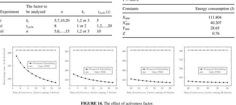
First, four test cases with n= 5, n = 7, n = 10 and n = 20 are simulated to observe the effect of the activeness factor (k) on energy savings. In each configuration, the activeness factor is assigned a value between 1 and 3. In this case, the sum of
the activeness factors for all devices is between n and 3n. The energy consumptions of these configurations during a 400 s time interval are calculated approximately using the direct measurement values in Table 4and Equations4and 5. Using the same methodology, we calculate the energy consumption of the case in which only PSM is applied. The results are illu-strated in Fig. 14and show that as the sum of the activeness factors increases, the energy efficiency of our proposed scheme compared to the conventional PSM also increases. While the activeness factors increase, the total number of active and sleep cycles does not change for n stations at the end of all cycles. However, the number of transitions between active and sleep states decreases, and consequently the energy consumption due to transitions from sleep to active states is reduced. In other words, keeping some devices more active and favoring low-energy devices by putting them into sleep mode longer improve the energy efficiency obtained by our proposed approach.
Second, to analyze the influence of duty-cycle time on energy efficiency, we vary the cycle time (tcycle) from 1 to 20 s in our
simulations. The number of devices in the network is fixed to eight, which is a reasonable assumption for a home network. The activeness factor (k) is assigned in a uniform random man-ner to the devices and the sum of the activeness factors is set to 2n. The energy consumption of our scheme is calculated using the same methodology as in the previous simulation experi-ments. To compare, we also calculate the energy consumption when just PSM is used and when no sleep scheduling is used. As shown in Fig. 15, our proposed approach outperforms the conventional PSM for duty cycles longer than 3 s. The proposed approach is, however, not very efficient for smaller cycle times because the number of transitions between active and sleep
TABLE 3.Simulation parameters.
Experiment The factor to be analyzed n ki tcycle( )s i ki 5,7,10,20 1,2 or 3 5 ii tcycle 8 1 or 2 1,2,…,20 iii n 5,6,…,15 1,2 or 3 10
TABLE 4. Energy consumption values used in the formula for T= 400 s.
Constants Energy consumption (J)
X400 111.804 ¢ X400 40.207 Y400 28.65 Z 0.76 190 195 200
Sum of activeness f actors among 5 devices
T o tal energy cons. of all devices(J) Proposed Scheduling Only PSM 250 260 270 280
Sum of activeness f actors among 7 devices Proposed Scheduling Only PSM 340 360 380 400
Sum of activeness f actors among 10 devices Proposed Scheduling Only PSM 4 6 8 10 12 14 16 6 8 10 12 14 16 18 10 12 14 16 18 20 20 25 30 35 40 650 700 750 800
Sum of activeness f actors among 20 devices Proposed Scheduling
Only PSM
FIGURE 14.The effect of activeness factor.
states increases which causes a dramatic increase in energy con-sumption for very small duty-cycles.
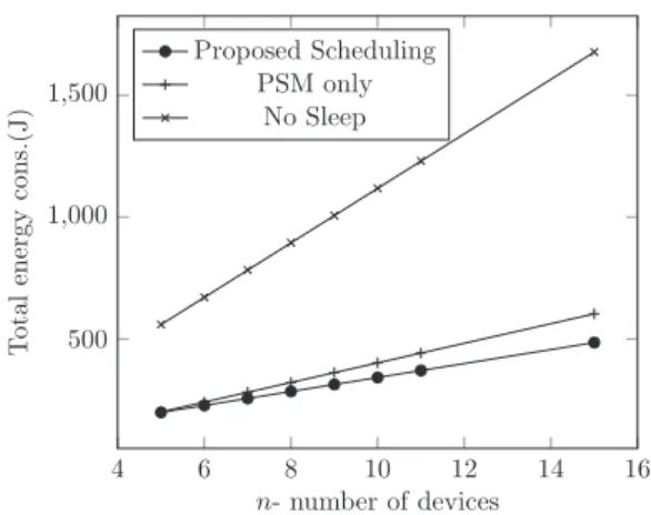
Third, to see the effect of network size, we calculated the total energy consumed in a larger network using the same methodology. We perform simulation experiments with dif-ferent numbers of devices, from 5 to 15, while assigning activeness factors uniformly and setting tcycle to 10 s. We
also compared the energy consumption in PSM and no-sleep modes. Figure17 and Table5show the results: as the number of devices increases, the energy efficiency of our proposed approach compared to other two cases increases as well. The results obviously reveal that the proposed scheme achieves energy savings up to 71% compared to the stand-ard infrastructure and up to 20% compared to the standstand-ard PSM. Additionally, device discoverability and availability are preserved. The test results with 15 devices also validate the scalability of the proposed approach. For a home net-work with a small number of devices (e.g. n= 2), however, using only PSM is more beneficial than our proposed approach, although our scheme still provides energy savings compared to the no-sleep case. Again, the energy consumed by an excessive number of transitions between sleep and
active state overshadows the energy savings achieved by our sleep scheduling.
Finally, we simulate a home M2M network that consists of six connected appliances: two refrigerators, one oven, one washer, one dryer and one coffee machine. According to the standby electric power consumption of electrical and electronic household appliances defined in the EU regulations [38], the power consumption of equipment in any condition providing only a reactivation function shall not exceed 0.5W, while the power consumption of equipment with a combination of reacti-vation function, and information displays shall not exceed 1W. Therefore, the limit for ovens, washers and dryers is 1W, because these appliances may have a display to show the clock in addition to buttons for reactivation. However, the limit for coffee machines is 0.5W, because they usually only have a reactivation function in standby mode. Based on these con-straints, we assign activeness factors to these appliances as shown in Table6. We set the cycle time (tcycle) to 5, 10 and
20 s in different experiments. Using the same methodology as in the previous simulations, we calculated the approximate total energy consumption for this scenario during a 400 s time interval for our proposed sleep scheduling, PSM and no-sleep case. As shown in Fig.16, our proposed approach outperforms the conventional 802.11 PSM.
TABLE 5. Comparison between proposed approach and the other cases for different n-devices in terms of energy efficiency.
n Savings compared to no sleep (%) Savings compared to PSM (%) 5 64.44 1.12 6 66.09 5.73 7 67.28 9.01 8 68.16 11.48 9 68.85 13.40 10 69.40 14.93 11 69.86 16.19 15 71.06 19.53
TABLE 6.The activeness factors (k) assigned to appliances.
Appliance
Activeness factor (k)
Limit for standby power (W) Refrigerator 3 None Oven 2 1 Washer 2 1 Dryer 2 1 Coffee machine 1 0.5 0 5 10 15 20 400 600 800
tcycle- duty-cycle time (s)
T otal energy cons. of all devices (J) Proposed Scheduling PSM only No Sleep
FIGURE 15.Evaluation of various duty cycles.
5 10 20 200 210 220 230 240 tcycle(s) T o tal Energy Cons. (J) Proposed Approach PSM
All these simulation results support the conclusion we drew from our test-bed experiments: that our proposed approach sig-nificantly reduces energy consumption in embedded home devices with a Wi-Fi module. In this manner, our proposal helps cope with the crucial drawback of Wi-Fi in terms of energy consumption when used in home M2M networks.
6. CONCLUSION
The initial studies on home M2M networks have open issues concerning real-world practicality for reasons such as the requirement for intermediate protocol translation gateways, high energy consumption and high cost. To handle such pro-blems, we presented a Wi-Fi- and IP-based energy-efficient M2M connectivity approach for home appliances. We exam-ined how to integrate Wi-Fi technology into smart embedded devices for smart home systems in an easy, secure, modular and energy-efficient way.
We implemented and demonstrated an integration model for Wi-Fi and embedded devices. Based on Soft AP mode and the embedded HTTP web server on the Wi-Fi module, we proposed an authentication and configuration model to allow an embedded device to connect to a specific home WLAN specified by the user. Then, the software stack with RTOS, TCP/IP Stack, Wi-Fi functions and platform func-tions were elaborated.
We proposed a sleep–wake scheduling algorithm based on the IEEE 802.11 power save mode to reduce the energy consumption of Wi-Fi-integrated consumer devices and machines. The proposed approach favors energy-constrained devices by forcing them to deeply sleep for a longer period of time. Sleep scheduling both reduces the energy consump-tion of embedded Wi-Fi networks and keeps the service availability of all devices in spite of sleeping devices. The proposed approach was evaluated using our prototype implementation and simulation experiments. The experimen-tal results obviously reveal that the proposed scheme
achieves energy conservation of up to 71% compared to the conventional system. We also compared our approach with a scheme that applies only the IEEE 802.11 power save mode. We observed that our proposed sleep scheduling on top of the PSM provides energy conservation of up to 20% compared to using only the PSM in a home M2M network. However, using only the PSM outperforms the sleep sched-uling approach for very small networks due to the energy loss through the state transitions of the proposed approach.
Although the experiments show that our proposed sleep scheduling algorithm significantly reduces the energy con-sumption of Wi-Fi modules in home M2M networks, in future work we feel we can extend it to achieve even better results. For example, the MCU on the proposed architecture could also go into deep sleep when its Wi-Fi interface is deactivated. Since the MCU in our prototype does not have such a sleep mode, only by deactivating the Wi-Fi interface could we put the module into sleep mode. In future work, ultra-low-power MCUs, which have a deep-sleep mode, could be used to attain better results.
In our study, we assumed that all Wi-Fi modules are time synchronized. As a future work, a time synchronization proto-col could be proposed before running our proposed sleep scheduling. Moreover, we applied our proposal to an infra-structure with one-hop communication, which has a wireless home access point. We could extend our proposed scheme by applying it to multi-hop networks by adapting the IEEE 802.11 PSM to an ad hoc mode and proposing energy-efficient multi-hop routing protocols.
In conclusion, existing M2M applications based on Wi-Fi can easily incorporate the proposed approach to use device energy wisely, since the proposed procedure requires no changes to the standard IEEE 802.11 MAC. The prototype implementation also strengthens the argument that the pro-posed scheme is feasible for real-life deployment.
FUNDING
The Scientific and Technological Research Council of Turkey (TÜBİTAK) under project 113E274.
REFERENCES
[1] Starsinic, M. (2010) System Architecture Challenges in Home M2M Network. In Long Island Systems Applications and Technology Conf. (LISAT), May, pp. 1–7.
[2] Zhao, X. (2010) The Strategy of Smart Home Control System Design Based on Wireless Network. In 2nd Int. Conf. Computer Engineering and Technology (ICCET), April, pp. 37–40.
[3] Tekbiyik, N. and Uysal-Biyikoglu, E. (2011) Energy efficient wireless unicast routing alternatives for machine-to-machine networks. J. Netw. Comput. Appl., 34, 1587–1614. Dependable
4 6 8 10 12 14 16 500 1,000 1,500 n- number of devices T otal energy cons.(J) Proposed Scheduling PSM only No Sleep
FIGURE 17.The effect of number of devices.
Multimedia Communications: Systems, Services, and Applications.
[4] Kenawy, A., Badawi, G., Makar, M., Onsy, M., Hanna, R., Halawa, H., Refaat, T., Daoud, R., Amer, H. and Elsayed, H. (2013) WSN Goodput and Energy Consumption for Various Wireless Communication Standards. In Int. Conf. Technol. Adv. Electrical, Electronics and Computer Engineering (TAEECE), May, pp. 40–45.
[5] Shahzad, K. and Oelmann, B. (2014) A Comparative Study of In-sensor Processing vs. Raw Data Transmission using ZigBee, BLE and Wi-Fi for Data Intensive Monitoring Applications. In 2014 11th Int. Symp. Wirel. Commun. Syst. (ISWCS), August, pp. 519–524.
[6] Chen, M., Wan, J., Gonzalez, S., Liao, X. and Leung, V. (2014) A survey of recent developments in home M2M net-works. IEEE Commun. Surv. Tutor., 16, 98–114.
[7] Jara, A., Martinez-Julia, P. and Skarmeta, A. (2012) Light-Weight Multicast DNS and DNS-SD (lmDNS-SD): IPv6-Based Resource and Service Discovery for the Web of Things. In 6th Int. Conf. Innovative Mobile and Internet Services in Ubiquitous Computing (IMIS), July, pp. 731–738.
[8] Mehmood, Y., Görg, C., Muehleisen, M. and Timm-Giel, A. (2015) Mobile M2M communication architectures, upcoming challenges, applications, and future directions. EURASIP J. Wirel. Commun. Netw., 2015, 250.
[9] Schramm, P., Naroska, E., Resch, P., Platte, J., Linde, H., Stromberg, G. and Sturm, T. (2004) A service gateway for net-worked sensor systems. IEEE Pervasive Comput., 3, 66–74. [10] Yigit, M., Yoney, E. and Gungor, V. (2013) Performance of
MAC Protocols for Wireless Sensor Networks in Harsh Smart Grid Environment. In 1st Int. Black Sea Conf. Commun. Netw. (BlackSeaCom), July, pp. 50–53.
[11] Zhi-Gang, L. and Wei, H. (2012) The Design of Smart Home System Based on Wi-Fi. In Int. Conf. Computational Problem-Solving (ICCP), October, pp. 454–456.
[12] Lu, X.-C., Huang, J., Wu, M.-C., Liu, X.-F. and Ding, Y. (2010) IP-Based Connectivity with IEEE 802.11 Embedded Networks. In 2nd Int. Conf. Inf. Sci. and Engineering (ICISE), December, pp. 2147–2150.
[13] Chen, S.-L., Chang, S.-K. and Chen, Y.-Y. (2015) Development of a multisensor embedded intelligent home environment moni-toring system based on digital signal processor and Wi-Fi. Int. J. Distrib. Sens. Netw., 2015.
[14] Nguyen, M.S. and Le-Trung, Q. (2014) Low-Power and Cost-Effective WiFi Sensor Motes for Wireless Embedded Internet Applications. In 2014 Int. Conf. on Advanced Technologies for Communications (ATC 2014), October, pp. 441–445.
[15] Can Filibeli, M., Ozkasap, O. and Reha Civanlar, M. (2007) Embedded web server-based home appliance networks. J. Netw. Comput. Appl., 30, 499–514.
[16] IEEE draft standard part 11: Wireless LAN medium access control (MAC) and physical layer (PHY) specifications. IEEE P802.11s/D12.0, May 2011, 1–391.
[17] Zhu, Y.-H., Lu, H.-C. and Leung, V. (2012) Access point buf-fer management for power saving in IEEE 802.11 WLANs. IEEE Trans. Netw. Serv. Manag., 9, 473–486.
[18] Tabrizi, H., Farhadi, G. and Cioffi, J. (2012) An Intelligent Power Save Mode Mechanism for IEEE 802.11 WLAN. In IEEE Global Commun. Conf. (GLOBECOM), December, pp. 3460–3464.
[19] Lin, H.-H., Wei, H.-Y. and Vannithamby, R. (2012) DeepSleep: IEEE 802.11 Enhancement for Energy-Harvesting Machine-to-Machine Communications. In IEEE Global Commun. Conf. (GLOBECOM), December, pp. 5231–5236. [20] Chen, Y.-S., Tsai, M.-K., Chiang, L.-S. and Deng, D.-J. (2011)
Adaptive Traffic-Aware Power-Saving Protocol for IEEE 802. 11 Ad Hoc Networks. In IEEE 17th Int. Conf. Parall. Distrib. Syst. (ICPADS), December, pp. 866–871.
[21] Pack, S. and Choi, Y. (2005) An adaptive power saving mechan-ism in IEEE 802.11 wireless IP networks. J. Commun. Netw., 7, 126–134.
[22] Glaropoulos, I., Mangold, S. and Vukadinovic, V. (2013) Enhanced IEEE 802.11 Power Saving for Multi-Hop Toy-to-Toy Communication. In IEEE and Internet of Things, IEEE Int. Conf. IEEE Cyber, Physical and Social Computing (iThings/CPSCom), August, pp. 603–610.
[23] Levy, D. and Kotuliak, I. (2016) WLAN power saving using packet overhearing reduction. Telecommun. Syst., 61, 43–57. [24] Huang, P., Chen, H., Xing, G. and Tan, Y. (2009) SGF: a
state-free gradient-based forwarding protocol for wireless sen-sor networks. ACM Trans. Sens. Netw., 5, 14:1–14:25. [25] Chen, H., Liu, B., Huang, P., Liang, J. and Gu, Y. (2012)
Mobility-assisted node localization based on toa measurements without time synchronization in wireless sensor networks. Mob. Netw. Appl., 17, 90–99.
[26] Wang, G. and Chen, H. (2011) An importance sampling method for tdoa-based source localization. IEEE Trans. Wirel. Commun., 10, 1560–1568.
[27] Chen, H., Gao, F., Martins, M., Huang, P. and Liang, J. (2013) Accurate and efficient node localization for mobile sensor net-works. Mob. Netw. Appl., 18, 141–147.
[28] IETF (2012) Multicast DNS draft-cheshire-dnsext-multi-castdns-15 [online].
[29] Apple (2016) Bonjour for developers [online]. [30] Ltd, R. T. E. (2016) About FreeRTOS [online].
[31] Zoican, S. and Vochin, M. (2012) LwIP Stack Protocol for Embedded Sensors Network. In 9th Int. Conf. Commun. (COMM), June, pp. 221–224.
[32] Alliance, W.-F. (2007) Wi-fi protected setup specification. WiFi Alliance Doc., 1, 8–13.
[33] Zisiadis, D., Kopsidas, S., Varalis, A. and Tassiulas, L. (2012) Enhancing WPS security. IFIP Wirel. Days (WD), November, 1–3.
[34] Wang, X., Xing, G., Zhang, Y., Lu, C., Pless, R. and Gill, C. (2003) Integrated Coverage and Connectivity Configuration in Wireless Sensor Networks. In Proc. 1st Int. Conf. Embed. Netw. Sensor Systems, New York, NY, USA SenSys ’03, pp. 28–39. ACM.
[35] Zhu, C., Zheng, C., Shu, L. and Han, G. (2012) A survey on coverage and connectivity issues in wireless sensor networks. J. Netw. Comput. Appl., 35, 619–632. Simulation and Testbeds.
[36] Yardibi, T. and Karasan, E. (2010) A distributed activity sched-uling algorithm for wireless sensor networks with partial cover-age. Wirel. Netw., 16, 213–225.
[37] Wang, J., Li, D., Xing, G. and Du, H. (2010) Cross-layer sleep scheduling design in service-oriented wireless sensor networks. IEEE Trans. Mob. Comput., 9, 1622–1633.
[38] DG Energy, E.E.U. (2013) Commission regulation (EU)— ecodesign—standby and off mode. Off. J. Eur. Union, 801, 1–12.
[39] Broadcom (2016) Wireless Internet Connectivity for Embedded Devices—User Manual [online].