ScienceDirect
Materials Today: Proceedings 18 (2019) 1927–1935 www.materialstoday.com/proceedings
2214-7853 © 2019 Elsevier Ltd. All rights reserved.
Selection and/or Peer-review under responsibility of INTERNATIONAL CONGRESS ON SEMICONDUCTOR MATERIALS AND DEVICES.
ICSMD-2017
Investigation of electrical conductivity of PAN nanofibers
containing silica nanoparticles produced by electrospinning method
Olivier Mukongo Mpukuta
a,*, Kevser Dincer
a, Mehmet Okan Erdal
baFaculty of Engineering, Department of Mechanical Engineering, 42003 , Selcuk University, Turkey
bSeydişehir Vocational School, Necmettin Erbakan University, Turkey
Abstract
This paper sheds new light on how an amount of silica nanoparticles (1, 3 and 5 wt. %) acts on the morphology, the hydrophobicity and on the electrical conductivity of polyacrylonitrile (PAN) nanofibers. In this study, electrospinning technique was used to fabricate nanofibers composites consisting of PAN, dimethylformamide (DMF) and silica at two different applied voltages (15 kV and 20 kV). The scanning electron microscopy (SEM), X-ray diffraction technique (XRD), contact angle technique and the four-point probe technique were respectively used to investigate the morphology and diameter range, the crystalline structure, the hydrophobicity and the electrical conductivity of the obtained nanofibers. At the end, different results of the investigation were compared each other and discussed.
© 2019 Elsevier Ltd. All rights reserved.
Selection and/or Peer-review under responsibility of INTERNATIONAL CONGRESS ON SEMICONDUCTOR MATERIALS AND DEVICES.
Keywords: Electrical conductivity; Electrospinning process; PAN nanofibers; Silica nanoparticles
1. Introduction
For more than a decade the fabrication of nanofibers containing silica nanoparticles has received the great attention of both scientist and industrial area due to their various applications possibilities: environmental protection, biomedical, composites, microelectronics, agriculture and so forth. Nanofibers are defined as fibers with diameters in the order of 100 nanometers. Researchers argue that when polymer fiber materials are shrunk from micrometer to nanometer, several characteristics are improved compared with any other known form of material. As an important
* Corresponding author. Tel.:+90 5443219091; fax: + 90 332 241 0635.
one-dimensional nanomaterial, nanofibers have extremely high specific surface area because of their small diameters and nanofibers membranes are highly porous with excellent pore interconnectivity.
Fabrication of nanofibers containing metal nanoparticles has received great attention, because the as-prepared nanocomposites take advantage of both the unique properties of metal nanoparticles and the outstanding characteristics of polymer nanofibers [1,2]. Due to their high specific surface area and high interpenetrating capacity in other materials, polymer nanofibers are one of the most important nanostructured materials with various interesting applications such as in microelectronics, protective clothing, filtration, water treatment, biomedical applications, energy- related needs and so forth [2,3].
Over the past few years, more attention has been paid to the preparation of nanofibers containing silica nanoparticles that can be used in biomedical applications and environmental protection. So far, it has been proved that silica nanoparticles can be used as electronic substrates, emulsifiers, stabilizers, thin films, electrical or thermal insulators and so on [4]. From the open literature, it was reported that the performance of the as-prepared nanofibers containing metal nanoparticles does not only depend on the individual component properties but also by the degree of dispersion of nanoparticles in the polymer and the interfacial interaction to enhance or limit its overall properties [4]. It has reported that silica nanoparticles electrospun with polystyrene dispersions are extensively utilized in the production of superhydrophobic meshes [5,6,7]. Wen S. et al. have reported that silica nanoparticles electrospun with PVP followed by calcination can fabricate hierarchical SiO2 nanofibers with diameters of about 500 nm and
particles sizes of tens of nanometers. Furthermore, such electrospun SiO2 nanofibers have important applications in
adsorption and filtration [7,8].
Mirzaagha Babazadeh et al. [9] in their study, have fabricated conductive nanocomposites based on silica nanoparticles via In-situ chemical oxidative polymerization technique. They reported that the encapsulation of silicon oxide nanoparticles by polyaniline (PANI) has had a strong effect on the morphology of nanocomposites. Moreover, the electrical conductivity of the as-prepared nanocomposites was higher at low silicon oxide nanoparticles content than that of neat PANI. However, increasing amount of silica nanoparticles decreased the value of electrical conductivity.
Different methods were reported for the fabrication of nanofibers such as drawing, template synthesis, phase separation, self-assembly, Chemical vapor deposition, wet chemical synthesis, electrospinning and so forth [10]. Among these aforementioned methods, electrospinning is currently recognized as the only technique that allows the preparation of continuous fibers with diameters down to a few nanometers [7,10,11].Moreover, compared to other techniques, electrospinning has the merits of simplicity, high efficiency, low cost and high reproducibility [12].
Polyacrylonitrile is extensively used in electrospinning and exhibits many properties such as higher hydrophobicity and insolubility in wide range of solvents [7,9].Although PAN nanofibers prepared with various inorganic nanoparticles have been investigated by many researchers in recent years, to the best of our knowledge, no investigation of electrical conductivity of the as- spun PAN nanofibers containing silicon dioxide (SiO2) has not
been reported yet. This paper sheds new light on how an amount of silica nanoparticles (1, 3 and 5 wt. %) acts on the morphology, the hydrophobicity and on the electrical conductivity of PAN nanofibers.
2. Experimental section
2.1. Materials
Polyacrylonitrile (PAN, Mw =150,000g/mol) powder, silica (99.8%, Mw = 60.08g/mol) and N, N- Dimethylformamide anhydrous, (DMF, 99.8%) were purchased from Sigma Aldrich chemistry Co. All chemicals were used as- received without further purification.
2.2. Pure PAN nanofibers fabrication
Different PAN/DMF solutions with polymer rate of 8 wt. %, 9 wt. %, 10 wt. % and 11 wt. % by mass were prepared as follows. The required amount of PAN was dissolved in DMF and stirred using a magnetic stirrer device
at 85°C and 1200 rpm for an hour so as to obtain homogenized solutions. The prepared electrospinning solutions were poured into 2.5 mL syringes with 0.8 mm as inner diameter respectively.
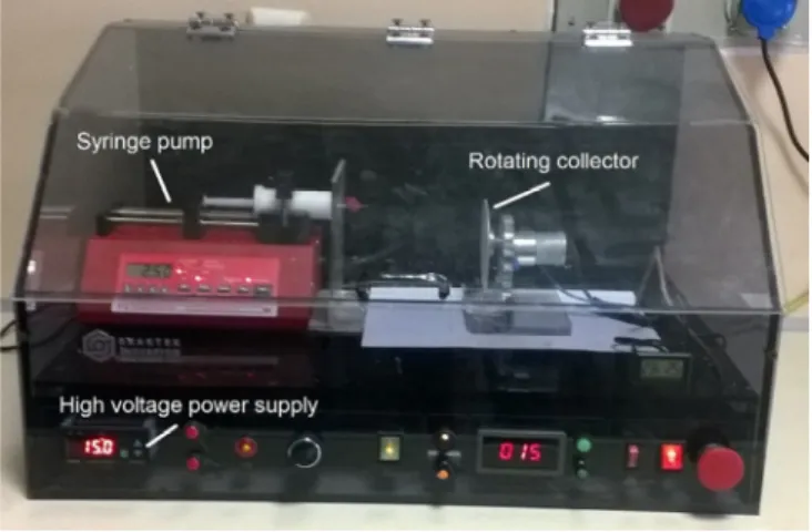
The experimental setup consisted of a syringe pump, sample collector and a high-voltage power supply which can generate DC voltage up to 40 kV. The spinning solution was held in a horizontal syringe with a stainless steel needle. The needle was electrically connected to a positive high voltage power supply. Whereas, the metallic disc used as collector was electrically connected to a negative high voltage power supply. The rotational speed of the collector during electrospinning was setup at 112.5 rpm. The needle to collector distance was 12 cm and the solution flow rate was maintained at 2.5 mL/hr. using a digitally controlled syringe pump. In this study, the electrospin nanofibers were performed at 15 kV and 20 kV, respectively and keeping all the aforementioned conditions constant. The electrospinning process was carried out in a closed environment inside a transparent box at a room temperature as it can be seen from the Fig.1.
Fig. 1. Electrospinning setup.
2.3. PAN/DMF/SiO2 NPs nanofibers fabrication
In this paper, among different electrospinning solutions used to fabricate pure PAN nanofibers, the electrospinning solution containing 9 wt. % of PAN not only led to a good average diameter but also to beads-free and uniform fibers. Therefore, 9 wt. % of PAN was opted in this paper. The PAN/DMF solutions were prepared as reported in the section above. Once the homogeneous PAN/DMF solution was obtained, a specific amount of silica nanoparticles (1, 3 and 5 wt. %) were added into each prepared PAN/DMF solution, respectively. Furthermore, so as to be homogenized, the obtained solutions (PAN/DMF/SiO2 NPs) were stirred using a magnetic stirrer for an hour at
85 °C. The prepared solutions were fed into 2.5 mL syringes with 0.8 mm as inner diameter respectively. For each silica nanoparticles content in PAN/DMF solutions, two samples of nanofibers were produced at 15 kV and 20 kV, respectively, using similar ambient conditions and processing parameters highlighted previously.
2.4. Characterization
Scanning electron microscopy (SEM, Zeiss Evo LS10) was used to evaluate the morphology and observe the dispersion of nanoparticles. Since a conductive coating is recommended to prevent charging of specimen with an electron beam in conventional scanning electron microscopy technique, the obtained electrospun nanofibers were brought in a sputter machine (Cressington Sputter Coater) in order to cover specimens with a thin layer of conducting material. Then, the coated nanofibers were characterized using SEM.
The image J setup was used in order to examine the uniformity and to estimate the average diameter of the as-spun fibers.
A four-point probe device (ENTEK Elk. FPP-460 with Pt probes) was used to measure the electrical conductivity of nanofibers at room temperature.
The hydrophobicity of pure PAN and nanocomposites fibers were investigated using the contact angle measurement device (Dataphysics instruments GmbH, model OCA15 Pro, version 1.3). In this paper, in order to study the hydrophobicity of the as-spun nanofibers a dosing volume of 2 μL of water was used at 0.5 μL/s as dosing rate.
The crystallinity of synthesized pure PAN and composite nanofibers was further investigated by X-ray diffraction (XRD, Bruker advanced X-ray solutions D8). The XRD operating with a CuKα radiation source (wavelength λ= 0.15406 nm) was used. The X-ray beam were generated at 40 kV and 40 mA power. The XRD profiles were recorded from 10° to 90° for 2θ and at the scanning speed of 5 °/min.
3. Results and discussion
3.1. Morphology of pure PAN nanofibers
It has been reported that morphology such as fiber diameter and its uniformity of the as-pun polymer fibers are linked to many processing parameters [13]. However, many researchers have highlighted that under certain conditions, not only uniform fibers but also beads-free fibers could be fabricated [13,14]. Therefore, in this paper so as to obtain beads-free and uniform PAN nanofibers, different electrospinning solutions with different PAN contents (8, 9, 10 and 11 wt. % by mass) were prepared and electrospun at 15 kV and 20 kV, respectively. The morphology of the as-fabricated PAN nanofibers was characterized by SEM and their respective results were displayed in Fig.2 and Fig.3. It was observed that even though at 8 wt. % of PAN, nanofibers with smaller average diameters were obtained but an important number of spindle-like beads were visible as well. The electrospinning of solutions containing a PAN content higher than 8 wt. % led to the fabrication of fibers without beads. It is worth to say that at 11 wt. % of PAN, branched fibers were observed. The formation of branched fibers can be justified by the instability of the jet due to the discrepancy between the electrical forces and surface tension. It was reported that such instability can decrease its local charge per unit surface area by ejecting a smaller jet from the surface of the primary jet or by splitting apart into two smaller jets [7,14,15]. In 9 and 10 wt. % of PAN uniform nanofibers without any spindle-like beads were obtained. In addition, it was observed that increasing the PAN concentration, generally led to the increase of the fibers average diameter in both 15 kV and 20 kV. By keeping the concentration constant and changing the applied voltage, it was observed an increase in nanofibers diameter with the increase of the applied voltage except for 11 wt. % at 20 kV wherein the average diameter where smaller than those performed at 15 kV. By keeping the applied voltage constant and changing the concentration of the PAN, it has been observed that thin nanofibers were obtained with a decrease in PAN concentration. According to all highlighted observations, the electrospinning solution containing 9 wt. % of PAN was selected for the continuation of this paper.
3.2. Morphology of composite nanofibers
Fig. 4 and Fig. 5 show the SEM images of the as-pun PAN/SiO2 composite nanofibers which contain different
SiO2 concentration (1, 3 and 5 wt. %) performed at 15 kV and 20 kV, respectively. The pure PAN nanofibers from 9
wt. % of PAN appear in both cases (15 kV and 20 kV) to be very uniform, smooth and without any beads. However, although all the fabricated nanocomposites were beads-free, but all the SEM images indicate that the agglomeration of the silicon dioxide nanoparticles on the surface was obviously observed. Therefore, no-one would dispute that the addition of SiO2 nanoparticles in the electrospinning solution has affected the morphology and average diameter of
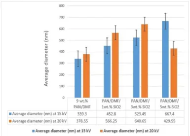
the electrospun composite nanofibers. Fig.6 compares the diameters of pure PAN nanofibers to PAN/SiO2
nanocomposites fabricated with different concentration of silicon dioxide nanoparticles. All the evidence suggests that the pure PAN nanofibers diameters were found to be smaller than any diameter of PAN/SiO2 nanocomposites
fabricated at 15 kV and 20 kV, respectively.
The average diameters of composite nanofibers performed at 15 kV increased with the SiO2 nanoparticles
concentration in the electrospinning solution. The fibers diameter increased from 339.3 nm for pure PAN fibers to 452.8 nm, 523.45 nm and 667.4 nm for PAN/SiO2 composite nanofibers containing 1, 3, and 5 wt. % of silica
nanoparticles, respectively. Even though all the composite nanofibers obtained at 20 kV have a higher diameter that those of pure PAN, it can be seen from Fig.6 that compared to 3 wt. % , the addition of 5 wt. % of silicon dioxide nanoparticles in the electrospinning solution did not increase the diameter of the as-spun nanofibers. This phenomenon may be justified by the increase in the conductivity of the electrospinning solution which could lead to more charges during electrospinning process. The increase in charge has as result of reducing the critical voltage of the solution and therefore producing nanofibers with small diameters [16]. It was also observed that PAN/SiO2
composite nanofibers fabricated at 15 kV presented smaller diameter than those performed at 20 kV except for 5 wt. % SiO2 wherein the average diameter where smaller than those performed at 15 kV.
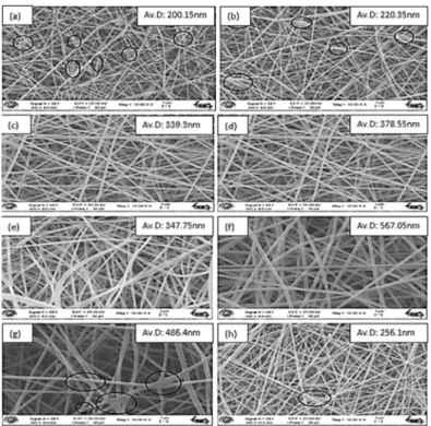
Fig. 2. SEM images of Electrospun pure PAN nanofibers from various concentrations and applied voltages: (a) 8 wt. % and 15 kV, (b) 8 wt. % and 20 kV, (c) 9 wt. % and 15 kV, (d) 9 wt. % and 20 kV, (e) 10 wt. % and 15 kV, (f) 10 wt. % and 20 kV, (g) 11 wt. % and 15 kV, (h) 11 wt. % and 20 kV. All other processing parameters kept constant (flow rate: 2.5 ml/hr.; Collector rotational speed: 112.5 rpm; needle to collector distance: 12 cm).
Fig. 4. SEM images of as-spun PAN and PAN/SiO2 nanofibers from 9wt % of PAN solution containing different
SiO2 contents performed at 15 kV: (a) 9 wt.% PAN, (b) 1 wt.% SiO2, (c) 3 wt. % SiO2, (d) 5 wt.% SiO2. All other
processing parameters held constant (flow rate: 2.5 ml/hr.; Collector rotational speed: 112.5 rpm; needle to collector distance: 12 cm).
Fig. 5. SEM images of as-spun PAN and PAN/SiO2 nanofibers from 9 wt.% of PAN solution containing different
SiO2 contents performed at 20 kV: (a) 9 wt. % PAN, (b) 1 wt. % SiO2 , (c) 3 wt. % SiO2 , (d) 5 wt.% SiO2. All
other processing parameters held constant (flow rate: 2.5 ml/hr.; Collector rotational speed: 112.5 rpm; needle to collector distance: 12 cm).
Fig. 6. Comparison of average diameter (nm) of the as-fabricated pure pan nanofibers and PAN/SiO2 composite nanofibers at different silica
3.3. Electrical conductivity
The preparation of nanocomposites consisting of polymers and nanoparticles has drawn greater attention in fact that they can be used in various applications such as Proton Membrane Exchange, supercapacitors, electromagnetic shielding for computers, light emitting diodes, layers and coatings, metal proton, flexible nanoelectronic devices and so forth [12,17,18]. In this paper, a four-point probe method was used to measure at room temperature the electrical conductivity of the fabricated composite materials.
Fig.7 shows the variation of electrical conductivity for different electrospinning voltages and different silica nanoparticles content. The experimentation results have shown that the applied voltage during the electrospinning process has a prominent effect on the electrical conductivity (E.C) of the as-spun nanofibers. Most of the experimentation results of this paper indicated that values of electrical conductivity of nanofibers produced at 15 kV were higher than that of nanofibers produced at 20 kV. For instance, the electrical conductivity of the as-spun pure PAN nanofibers at 15 kV was higher than that of pure PAN nanofibers at 20 kV. Their electrical conductivity values were 5.81×10⁻³ S/cm and 1.63×10⁻³ S/cm for pure PAN nanofibers fabricated at 15 kV and 20 kV, respectively.
From experimentation results, all the evidence suggested that independently of the applied voltage during the electrospinning process, the addition of silica nanoparticles (SiO2 NPs) up to a certain amount in PAN/DMF
solution improved the electrical conductivity of the resultant nanocomposites. For SiO2 - based nanocomposites
fibers produced at 15 kV, the conductivity of nanofibers containing 1, 3 and 5 wt. % SiO2 was 7.10×10 ,
8.26×10 and 4.19×10 S/cm, respectively. As can be observed the electrospun PAN nanofibers reinforced with 3 wt. % of silica performed at 15 kV present a 42.16 % increase in the value of electrical conductivity compared to its pure PAN nanofibers. However, it has been observed that the nanofibers reinforced with 5 wt. % of silica have presented an electrical conductivity lower than that of pure PAN nanofibers. However, for SiO2-based
nanocomposites fibers fabricated at 20 kV, the conductivity of nanofibers containing 1, 3 and 5 wt. % SiO2 was
8.11×10 , 5.96×10 and 2.08×10 S/cm, respectively. It was found that even though the values of electrical conductivity of composite nanofibers were higher than that of pure PAN nanofibers, the electrical conductivity of fibers decreases with increase of silica nanoparticles contents in the electrospinning solution. The electrospun PAN nanofibers reinforced with 1 wt. % of silica performed at 20 kV present a 397.54 % increase in the value of electrical conductivity compared to pure PAN nanofibers. Whereas, only a 27.6 % increase in the value of electrical conductivity was observed at 5 wt. % of silica content.
Fig. 7. Electrical conductivity of the as-fabricated pure pan nanofibers and PAN/SiO2 composite nanofibers at different electrospinning voltage
3.4. Contact angle results
This section presents the results of the investigation on the hydrophobic behavior of the as-spun fibers in the presence or absence of silicon dioxide (SiO2) nanoparticles. Since the main purpose of this paper is to investigate the
effect of silicon dioxide nanoparticles on the electrical conductivity of the electrospun composite nanofibers, in this section only nanocomposite samples which presented the highest electrical conductivity were investigated and compared to pure PAN nanofibers results. The thin film samples of nanocomposite fibers were placed on a glass plate and a single drop of water deposited on top of the films by a syringe. At least three static contact angles were measured at different positions and the obtained results were averaged for each sample. Fig.8 shows the average static water contact angles of pure PAN nanofibers and composite nanofibers containing 1 wt. % and 3 wt. % of SiO2 nanoparticles concentration. As can be seen from the Fig.8, the applied voltage during electrospinning process
did not affect the hydrophobic behavior of nanofibers. The contact angles for pure PAN nanofibers were 120.8°and 115.3° for samples electrospun at 15 kV and 20 kV, respectively, and those of composite nanofibers were 123.06° and 125.42° for samples electrospun at 15 kV and 20 kV, respectively. For both applied voltages (15 kV and 20 kV) the contact angles were greater than 90°, hence, wetting of the surface of nanofibers is unfavorable so the liquid will bead on the surface. Although the incorporation of silicon dioxide nanoparticles in the electrospinning solution led to an increase of contact angle values of the as-spun nanofibers, but did not change its hydrophobic state.
Fig. 8. Average static contact angles of the as-fabricated pure pan nanofibers Fig. 9. XRD patterns of pure PAN and PAN/SiO2 composite
and PAN/SiO2 composite nanofibers at different electrospinning voltages. nanofibers.
3.5. X-Ray Diffraction results
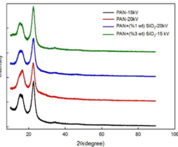
The pure PAN and based-silica nanocomposites fibers were characterized by X-ray diffractometer (XRD) and the results were shown in Fig.9. As can be observed that three broad diffraction peaks were found around 2θ = 11.5°, 2θ = 22.8° and 2θ = 34.3° for each sample. This means that a considerable parts of PAN and silica were in the amorphous form, but a few of them were crystalline. For PAN nanofibers containing 3 wt. % of SiO2 a new peak for
silica was observed at around 16.4° with (101) as Miller indices. In addition, the XRD results for both pure PAN and silica based nanofibers suggest that the full width at half the maximum (FWHM) of peaks are large and therefore correspond to smaller crystallites.
In both cases (15 kV and 20 kV), it was observed that the values of peak intensity of pure PAN nanofibers were higher than those of nanofibers containing silica nanoparticles. Therefore, the degree of crystallization of nanocomposite fibers was lower than that of pure PAN. Respect to all observations made above, no-one would dispute that SiO2 nanoparticles has affected the crystallinity of PAN nanofibers.
4. Conclusions
Pure PAN nanofibers with diameter range from 200.15 to 486.4nm and from 220.35 to 567.05nm were successfully produced at 15kV and 20kV as electrospinning voltage, respectively. Nanofibers containing 9wt. % of PAN and different silica NPs content (1, 3 and 5 wt. %) were successfully produced using electrospinning technique. The effect of silica nanoparticles on nanofibers morphology and diameters was investigated. It was found that increasing silica NPs content led to an increase of nanofibers diameters, and affected negatively the morphology of electrospun nanofibers.
The difference between pure PAN nanofibers and PAN nanofibers containing silica NPs in terms of electrical conductivity was spotted. The results showed that the presence of silica NPs content in the PAN nanofibers could enhance its electrical conductivity. It was observed that higher values of electrical conductivity were obtained at low silica NPs content in the electrospinning solution.Furthermore, the results revealed that electrospinning voltage has a prominent effect on electrical conductivity since at even amount of silica NPs most of the nanofibers electrospun at 15kV had higher values than those of 20 kV.
The XRD patterns revealed three broad diffraction peaks around 2θ =11.5°, 2θ =22.8° and 2θ = 34.3°. This means that a considerable parts of silica nanoparticles were amorphous, but a few of them were crystalline. A peak of silica was observed at around 16.4° with (101) as Miller indices. It was seen from Sigmapot setup that peaks of pure PAN were higher than those of nanofibers containing SiO2 nanoparticles, therefore the degree of crystallization
of nanocomposite fibers was lower than that of pure PAN.
The contact angle results have revealed that SiO2 NPs have slightly improved the hydrophobic state of the
resultant composite nanofibers.
Acknowledgements
Authors acknowledged a financial support received from the research fund of the Selcuk University under Grant No. BAP 17201017.
References
[1] G. N. Sichani, Morshed, M., Amirnasr, M., Abedi, D., Journal of applied polymer science (2010) 116 (2), 1021
[2] Y. Wang, Yang, Q., Shan, G., Wang, C., Du, J., Wang, S., Li, Y., Chen, X., Jing, X., Wei, Y., Materials Letters (2005) 59 (24), 3046 [3] S. Rezaee, and Moghbeli, M., Iranian Journal of Chemical Engineering (2014) 11 (3)
[4] A. Kaur, Kaur, A., Saini, D., Res. Cell Int. J. Eng. Sci (2016) 6913, 40
[5] J.-M. Lim, Yi, G.-R., Moon, J. H., Heo, C.-J., Yang, S.-M., Langmuir (2007) 23 (15), 7981 [6] J.-M. Lim, Moon, J. H., Yi, G.-R., Heo, C.-J., Yang, S.-M., Langmuir (2006) 22 (8), 3445
[7] B. Ding, and Yu, J., Electrospun nanofibers for energy and environmental applications. Springer Science & Business Media: 2014 [8] S. Wen, Liu, L., Zhang, L., Chen, Q., Zhang, L., Fong, H., Materials Letters (2010) 64 (13), 1517
[9] M. Babazadeh, Zalloi, F., Olad, A., Synthesis and Reactivity in Inorganic, Metal-Organic, and Nano-Metal Chemistry (2015) 45 (1), 86 [10] Z.-M. Huang, Zhang, Y.-Z., Kotaki, M., Ramakrishna, S., Composites science and technology (2003) 63 (15), 2223
[11] D. Li, and Xia, Y., Advanced materials (2004) 16 (14), 1151
[12] X. Shi, Zhou, W., Ma, D., Ma, Q., Bridges, D., Ma, Y., Hu, A., Journal of Nanomaterials (2015) 16 (1), 122 [13] A. Haghi, Electrospinning of Nanofibers in Textiles. CRC Press: 2011
[14] A. Frenot, and Chronakis, I. S., Current opinion in colloid & interface science (2003) 8 (1), 64 [15] F. K. Zafarulla Khan, Shafi, H. Z., Nufaiei, F., Furquan, S. A., Matin, A., IJAENT (2015) 2 (3), 15
[16] M. Zamri, Zein, S. H. S., Abdullah, A. Z., Basir, N. I., International Journal of Engineering & Technology IJET-IJENS (2011) 11 (06) [17] J. M. Deitzel, Kleinmeyer, J., Harris, D., Tan, N. B., Polymer (2001) 42 (1), 261