iTw 2004, San Antonio. Texas. October 24.29.2004
Capacity Bounds
for
an Ultra-Wideband Channel Model
Erdnl Arikzn'
Dept. of Electrical-Electranics Engineering Bilkent University
Ankara, TR-06800, llnrkey e-mail: arikaneee. bilkent
.
edu. trAbstract - T h e r e is an o n g o i n g effort by t h e IEEE
802.15.3a s u b c o m m i t t e e to r e a c h a UWB p e r s o n a l a r e a n e t w o r k s t a n d a r d . We e s t i m a t e t h e achievable r a t e s f o r s u c h n e t w o r k s u s i n g a channel m o d e l spec- ified by t h e s a m e group. T h e analysis of t h i s chan- nel m o d e l is of i n t e r e s t i n light o f recent information- t h e o r e t i c work on m u l t i p a t h f a d i n g c h a n n e l s which show t h a t in order to take full a d v a n t a g e of s u c h channels' c a p a c i t y t h e t r a n s m i t t e d signals h a v e to be '&peaky" i n a c e r t a i n sense. T h e i m m e n s e h a n d w i d t h of t h e UWB c h a n n e l also s u g g e s t s at first t h a t p e a k y signals s h o u l d be used. Ho wever, unlike t h e m a n y o t h e r wireless s y s t e m s w h e r e the t r a n s m i t t e r e n e r g y is l i m i t e d , i n t h e UWB c h a n n e l o n l y t h e power spec- t r a l d e n s i t y of t h e t r a n s m i t t e d signal is c o n s t r a i n e d .
As
a resul t , t h e signal p o w e r c a n grow i n p r o p o r t i o n to t h e utilized h a n d w i d t h a n d p e a k y signals are n o t needed.I. INTRODUCTION
Initiated by FCC's release of t h e 3.1-10.6 GHa band for unli- censed operation under certain rcstrictions [I], there h an on- going standardization effort by IEEE subcommittee 802.15.3~. aimed a t creating B UWB physical layer for wireless personal area networks. The question of interest in this paper is to estimate the capacity of the TJWB channel. We begin with an initial cstiniate of the main operating parameters for such systems.
The FCC ruling stipulates t h a t the emitted power spectral density of signals he a t most -41.3 dBm/blHz within the above frequency range. First, we note that even if the transmitter utilizes the entire permissible bandwidth of 7.5 GHz, the total radiated power is -2.55 dBm, which is feasible even for bat- tery operated devices. So, the U W E system is not limited by available transmitter power.
Consider a UWB system employing signals of RF band- width W and duration T . The effective signal energy a t the receiver can be expressed as E = qWTL where 7 = -41 dBm/MHz and L is the loss factor from transmitter to re- ceiver. The received energy per degree of freedom equals
E. = &/WT = q L . We may write the loss L as consist- ing of two parts L = LlLz where
LI
is due to radiowave propagation, and L2 due to receiver non-idealities. TJnder freespace conditions, L I may be estimated by the Friis for- mula L 1 =(&)*
where we wsiime the receiver and tram- mitter antennas are isotropic a n d separated by a distance d , and take A, as the wavelength corresponding to the frequencyfc = 5092 MHz. There is no fundamental reason for using this
particular value for fc other than being able to compare our results with those in a propnsed standard [SI. The use of a 'This work was supported by European Union FP-6 Project NEWCOM, Contract IST N o E 507325.
single frequency to estimate the propagation loss over a wide range of frequencies is only an approximation; we refer to [2] for a discussion nf the error in this approximation. We take
LZ = 10 dB to account for receiver noise and other losses. Assuming the dominant noise in the system is white Gaussian with one-sided power-spectral demity No = -114 dBm/MHa, we obtain the SNR figures & n / N o = qL/No listed
in t h e following table. Also given in the table is the AWGN E - pacity C = W log ( I
+
a)
for an RF handwidth of W = 500 MHz, which is the minimum allowed bandwidth fnr a UWB system. The AWGN capacity may serve as a rough estimate of what range of rates may he expected in the UWB channel. Note that the AWGN capacity scales linearly with W since the signal power is allowed to grow linearly with W .T a b l e 1: Signal-trrnoise ratio and capacity estimates for t h e
UWB
cheiinel withW
= 500MHz RF
bandwidth.11.
1EEE UWB
CHANNEL MODELIEEE 80'2.1S.3a gmup published a channel model for UWB communications [4]. The channel is modeled as a linear system with an impulse response
h ( t j =
ax
c
a.,rd(t - Te -T,,d
(1) e iwhere a,,t is the path gain for the i t h "ray" in the Pth ''clus- ter." The number of clusters and rays within each cluster are random variables, as well as the path gains ail. Te is the random delay for the eth cluster and r*,e is the excess delay for the i t h ray in the t t h cluster. The term
4
repre- sents a common "shadowing" gain, which is independent of the (a.,e}. All gain terms are real-vahied random variables whose exact distributions can he found in [4]. For our pur- poses, it is only important to note that {ai,e} are specified as uncorrelated random variables with symmetric distributions around the origin.I n [4] four sets of parameters are defined, denoted as CM1- CM4, modeling various UWB environments. Some of the properties of these channel models are given in Table 2. The values in the table are computed after timediscretization of the fading coefficients
{pal,p}
using a sampling period ofT,
= 167 ps. In this table, N P ~ o ~ B stands for the number of paths whose intensity is within 10 dB of the intensity of the path with maximum energy. Likewise, N P (SSW) stands for the number of paths that capture 85% of the channel energy.Chiliinel energy is defined as the sum of the squared absolute vahies of the path gains. All quantities in the tahle represent averages over 100 samplc realizations for each channel model.
been exploited in
[e],
whose results are particularly relevant in the present context. To estimate the error introduced by using circular convolution, note thilt the maximum path delay T d for For exact details, we refer to [.I]1
Mo;LOdeI characteristics1
CMl1
CM2 CM31
Cb14I
RMS delay spread (ns) 5.28 X.03 14.28
N A o d e 13.3 18.2 25.8 41.4
N P (85%) 21.4 37.2 62.7 1 2 2 3 Channel energy (dR) -0.5
the UWB channel is on the order of 100 ns. Sa: the edge effects distvrt a fraction Td/Tc LI o f each transmitted block, which is clmrly neglipihlc. In fact, one can introduce a cyclic prefix as in OFDM systems a t negligible overhead t o remove the modeling inaccuracy due to use of circular convolution.
The channel model (2) is given in the time domain. An equivalent channel can he defined in the frequency domain by means of discrete Fourier transform. The DFT of a vector a = (a0
...,
~ K - I ) ~ is defined a the vector A = (Ao,.
.
.
given by the unitary transformation .4 = P a,
- K/2ijat+-e..
T akmg ' the DFT of the two sideswith Fk' -
of ( 2 ) , we obtain the frequency domain channel
Table 2:
IEEE UWB channel
model characteristics.111. BASEBAND C H A N N E L kfO DE L Y ! = f i G k . x k f z k ;
k
= 0 , . . . * K - 1 (4) A UWB communication system is a b a n d p a s systemaround some center frequency $,? with a bandwidth W con-
tained in the ranw 3.1 to 1 n . G GHz. As usual, we will analyze
The noise terms { Z r } are i.i.d. C N ( 0 , N o ) . The covariance of G is given by Cc = FG,F' and hus elements
"
( 5 ) 1
7
--jZ*e(i--h)/Ksuch B system after signals are translated to the baseband and time-discretizrd hy sampling at the Nyquist rate T, = 1/W.
The eauivalent complex baseband communication system
Cc(i,k) = IgeI e
L
will he modeled
as
a discrete-time vector channel where the transmitter sends B complex vector x = (xo,.. .
,
X K - I ) ~ and the receiver observes an output vector y = (yo,.. .
. ~ K - I ) ~given by
~h~ energy in a CT huxband
x(tj
of band- width W / 2 (corresponding to an RF bandwidth of W ) and duration T, is in a UWB system byT,.
1
Ix(t)12dt5
qZWT, =GWT,
(6) K-1y. = $ 7 k z ( , - r )
+
i,, i = 0 , .. .
, K ~ 1 (2)k=,I
where the terms are as defined in Sect. I. For the sampled system this constraint translates: into
where the additivo noise vector z = (z,,,.. . , z ~ - ~ ) ~ is corn. plex Gaussian with circularly symmetric (c.s.) independent components z,
-
CiV(U,No). ( A random vector z is said to he C.S. if has the same distribution as z for any real 0.) The hdsehand channel coefficient vector g = ( g o , .. .
,
gK--ljT is related to the original continuous-time channel impuke re- sponse byK - 1
(Xi/* <_ E,WT, = &.K (7) 1-0
or equivalently
Thus, the parameter E, may he interpreted as signal energy per complex baseband sample'
where d2,t = T e
+
r Z , e . Since ( m , , ~ } are aerc-mean and uucor- related. , ( 0 1 . )."..,
are also zero-mean and uncorrelated. Thus. theA
Iv.
U P P E R BOUNDS ON ACHIEVABLE RATEScovariance matrix C, = E ( g g t ) = dhg(lSll'). It is important to note that in the 802.15.3a UWB model, the coefficients { g k }
are neither Gaussian nor independent.
The DT channel model (2) is B simplified model in that it asssumes the channel state vector g stays k e d for a duration of
K
symbols. We further usssume that an independent saniple of g is sclccted at random far each new block of K symbols. Thus, the final model is a niemoryleSS vector channel. TheIn this section, we give upper bounds on the achievable rate I ( X ; Y ) for the channel (4) under various assumptions about the distribution of X . These upper hounds will clearly apply also t o the achievable rate r(x; y) for the equivalent channel (2) since I(x:y) = I ( X ; Y ) . Likewise, I ( X ; Y I G ) = r(x;ylg), etc. The basis of the upper hounds in this section is the identity vector length K is related to the coherence time T, of the
underlvine channel bv K = T-IT. where T. is the salnoline
r(x;
Y ) = I ( X G Y ) - r(G; YIX) I",(31
" _ -I . 1 "
period. Typical values are .~ Tc = 200 us and 500
5
W5
~ 7500 = r ( S Y ) - r(G; Y I X )MHz, yielding IO5
5
K5
1 . 5 . IO6.The summation in (2) is a circular convolution ooeration
. ,
where S = IS". ,~.
. . .
, S K - ~ ) ~ . , . Sk = ~ G I X I . . We will obtain with index (i - k) taken modulo K. We will use the notationg 0 I to denote the circular convolution. The idea of using circular convolution instead of linear convolution goes back to Hirt and Maisey 151, who used it to simplify the analysis of channels with intersymbol interference. This idea has also
ripper hounds on I ( X ; Y ) hy majoriaing I ( $ Y ) and minoriz- ing I ( G ; Y j X ) under certain additional assumptions.
Note that the covariance of S has the form Cs = K CcoCx
where o is the Hedamard product, i.e., entrywise product, of the two matrices. When C,y = &,I, (equivalently, when
C, = E ~ I K since C= = F ~ c ~ F ) , i ~ l l we will usually "me,
we obtain from (5) that
(10) Cs = KE, diag(Cc) = & . ~ I K
where diag(A) denotes the diagonal matrix obtained by taking the main diagonal of A and
llgll
denotes the Euclidean norm of g.L e m m a 1 For C,Y = E J K ,
Proof. Since the channel Y =
S
+
2 is additive Gaussian,the maximiimofI(S1Y)subject totheconstraint Cs =411g112 I Kis achieved by S
-
C N ( 0 , C s ) and equals the KNS of (11). L e m m a 2 Cutoff rate bound: Without any restrictions onthe channel input X and the coefficients G ,
I ( G ; Y I X )
2
Ex
{ - l o g E c . ~ [,-&ilXo(c-c')ll*I}
(l") where G' is a n independent copy of G. Equivalently,I ( g ; y l z )
2
E,{
- IogE,,,, [eC&11z@(s-g')'12I}
(13)where g' is an independent copy oJg
Proof. It is well-known that a mutual information term such as I ( G ; YjX) is lower-hounded by the corresponding 'kutoff rate" term R,,(G;YlX), which is defined as
EX { - l o g E D . ~ , [JJp(YIG,.Y)p(YIG',X)dY]} (14) Denoting the integral in the above expression by D ( G , G ' l X ) , a straightforward integration gives
and completes the proof of (12). Inequality (13) follows from l ( g ; y l z )
2
R o ( g ; y / z ) by showing that D ( g , g ' l z ) =The above results can be combined to give the following exp
( - & I I ~ @
( g - g W ) .upper bound on I ( X ;
U).
Proposition 1 Suppose the multipath coeficients {Sk} of the channel ( 2 ) a n zero-mean uneomlated random uaeables. Suppose the equivalent frequency domain channel (4) has an input X such that C.r = E J K . Then, the achievable m t e is bounded as
Remark. This result makes minimal assumptions about the distrihution of g . However, it has an ad-hoc nature due to the mixed use of the cutoff rate and mutual information, Better and more elegant bounds can be obtained if we make further assumptions about the distributions of g and X .
Lemma 3 Assume that the vector OJ channel coeficient.9 g b eomplez Gaussian with C.S. independent components. Let the input X to the channel (4) have covariance Cx = &,IK and
further assume that lXrl = Jor all k. Then,
Remark. QPSK signaling, which is the signaling scheme in a leading proposed UWB standard 131, satisfies the assumptions of this lemma on X .
Proof. Given
X ,
the situation is equivalent to an additive Gaussian noise channel with a Gaussian input G . So,I ( G ; Y I X ) = E x l o g d e t
I t can he verified easily that if e = (eo,.
. .
,
~ K - I ) ~ is a n eigen- value of Cc with eigenvdlue A: then f = ( j o , .. .
,
f K - t ) T with ji = ei1.Y: is an eigenvalue of X X ' o Cc with eigenvalue &aA. This is true for any vector X =(XO,.
. .
,
X K - I ) ~ whose elements have a constant modulus IX,I =a
z
0. Thus,and the proof is complete. A shorter proof can be given by observing that given X , in effect we have the vector channel
=
C+i,
wherek
= Y h / ( R . X , ) ,5,
= Z k / ( & X k ) , andZ
-
C N ( 0 , N o / ( K E , ) ) independent of X .Proposition 2 Suppose the multipath cneficients {gk} are independent C.S. complex Gaussian. Suppose the channel in- put in the frequency domain X has covariance Cx = &,IK
and its elements have a constant modulus, /Xrl =
G.
Then.Remark:
A
weakened version of (20) iswhich is obtained by using the inequalities In(1 f a )
5
a and In(1 + a )2
a-
a2/2. This bound is equivalent to the "faurth- egy bound" of Subramenim and Hajek 171. Also note that the RHS of (20) is non-negative (divide through by K and apply Jensen's inequality to the second logarithmic term).E x a m p l e 1 ( I E E E UWB Model) The Jading coefficients for the IEEE CJWB channel model
[4]
me not complex Gaus- sian as mentioned above. W e will nevertheless compute the bound ( 2 0 ) using the 2nd order Ytatistics of the IEEE model toobtain an estimate of the achieuable rates on the U W B chan- nel. We f i x the coheiance time as T, = 200 ps and the SNR
us &*/No = -3.88 dB colrespondinq to a range OJ 10 m. For
computations, W E use the 100 ChI4 channel realizations (LS
generated b y the MATLAB code given i n
[4].
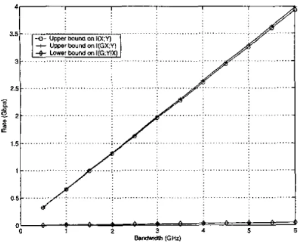
We consider sys- tems with RF bandwidths W ranging from 500 MHz to 6 GHz in Jteps of 500 MHr. The-sampling rate equals T, = I/W.A carrier Jrequeney fc = 5.092 GHz is used in computing the vector g ns given by (:J). We leave the mean channel enerqy 1Ig/l2 unnormalieed; it equals 1.4277 when ovemgui oucr the
100 sample realizations. Fig. 1 shows the bound (20) after
time-normalization through division by T,.
- I . . .
I
... 8.- G H l )Figure 1: Upper hound of Proposition 2 on
I ( X ;
Y)/T,.
It ma?, be of interest lo note that Jor the same set of pa- mmeters the f o u r t h q y bound (21) ranges from 29Y to 3941
Gbps as U’ ranges from 500 MHz to 6 GHz. The Jourthegy
bound does not go to zero (LS W i s increased because the sig- n d power scales linearly with W, unlike typical scenarios f o r
wireless communications where the total transmitter power i s
&d, In other words, for the UWB channel the SNR i n each
degree offmeedom cnn bc maintained at a constant level ewen
us one u ~ e s more dqreas oJfreedom; this prevents the signal from being “ouerspread. ”
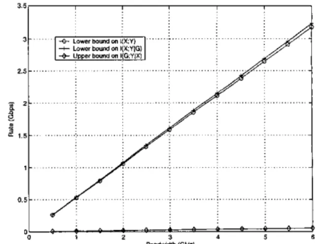
Infaet, for the above set of parameters, the correction term I ( G ; YjX) ia negligible compared to I ( X G ; Y ) which indicates that the coherence timc is long enough to carry out suficient amount of training at negligible cost to the overall rate. This picture changes, however, if one considers sending shod pack- ets over the UWB channel. Then, we need to replace K by the nvmbrr of samples in one packet duration. To study this case, consider packets OJ length 1 ws, which in effect i s equivalent to settinp T, = 1 ps. (We are nssuming that packets are sent in-
termittentlv with mean inter-tmnrmission tines greater than the actual channel coherence time of 200 p s . So, any channel state infonation gained in one packet’s reception i s useless for future packets.) Fig. 2 shows the bounds on the mutual in- formation terms for this ease. The bound on I ( G X ; Y ) / T , i s
the Bame as before. While before I ( G ; YIX)/T, was negligible
compared to I ( G X Y)/T,, now it i s quite stgnificlmt.
Figure 2: Upper hound of Proposition 2 on
I ( X ; Y ) / T ,
for short packets.
To give a lower bound on I ( X ; Y), we follow the argument in
[6] with some adjustment for the unequal path strengths. The lower bound is b a d on
r ( X ; Y ) = r ( X C ; Y ) - r ( C ; Y ~ . ~ )
(22) 2 I ( X ; Y I G ) - I ( G ; Y ( X )
We now take X as complex Gaussian with X
-
CN(O,&sIti).Then,
This is true for any distribution on the path gains g . If we Baume tliat g has independent C.S. components, then the
components of G are identically-distributed, and we have
To upper-bound the term I ( G Y l X ) , consider the time- domain channel representation and let s = g @ z. The CO- variance of S conditional on B given z equals BC,Bt where B is the K x K matrix with elements B., = z(.-,). Using the CiLnssian upper bound on mutual information for a given covariance,
where the fint inequality is Hadamad’s inequality [9, p. 1531 on the matrix A = A I
+
&
BtBC, and A(j) denotes the j t hv. A
LOWEK BOUND ON ACHIEVABLE RATEScolumn of A. T h e elements of A are
where
is Lhe normalized empirical autocorrelation of the sequence x.
It can be computed that
( 2 8 )
where U = 1 or 2 depending on K being odd or even, respec-
tively. This gives the bound
Thus, we have the following lower hound on channel capacity. P r o p o s i t i o n 3 The mutual i n f o m a t i o n I ( X ; Y ) over the channel (Z), with X
-
CiV(O,&.Iti), is lower-bounded b yE x a m p l e 2 (UWB capacity lower bound) We consider the same scenavio as i n Ez. 1 and compute the lower bound of Prop. 3. We have approximated the distribution of lG,j with
that of lGol in these computations. The resulting bounds ore
shown in Fig. 3 f o r T, = 200 ps ond i n Fig.
4
Jor T, = 1 p s . More work needs to be done to close the gap between these bounds and those of Ez. 1.VI. CONCLUSIONS
We have obtained upper and lower bounds on the achievable rate for the 8 0 2 . 1 5 . 3 ~ UWB channel model under certain as- sumptions and approximations on the distributions of path gains g and channel inputs X . The results show that the enormous bandwidth offered by the UWB channel can he uti- lized effectively by signaling schemes that spread the energy uniformly across each degree of freedom. This result is not surprising in view of the fact t h a t in the UWB channel model considered here the signal power is allowed to grow with the degrees offreedom employed. If the total signal power is fixed, the results of
[a]
and [7] show that such uniform spreading of signal energy across the available degrees of freedom leads t o a collapse of achievable rates beyond a certain point. Another conclusion is that under the target operating conditions for a UWB personal area network, it appears that relatively quick estimation of the channel state is passible, suggesting the use of feedback schemes for better channel utilization. We p r e pose finding better methods for estimating the UWB channel capacity and devising practical signaling schemes that can ef- ficiently utilize the channel capacity as subjects for further study. . . . . . .I
. . . !. ... .; . . . a * . : $ $ $ BYllmdlh ,GHI,Fignre 3: Lower
bound of Proposit,ion
3on
I ( X ;
Y)/T,.
. . . . . . ...
/i
-
Figure 4: Lower
bound of
Proposition3
onI ( X ; Y ) / T ,
for packet of length I ps.
REFERENCES
[I] “First Report and Order in the Matter of Revision of Pvrt 15 of the Commission’s Rules Regarding Ultra-Wideband Transmis- sion Systems,’ FCC, ET Docket 98153, FCC 02-48, Apr. 22, 2002.
[2] “UWB Channel Modeling Contribution from Intel,” 24 June 2002, IEEE PSOZ.15-02/2i9R-SG:~a. Online: http://grouper.ieee.org/groups/802/15/pub/20~~/.J“l02/ [3] “Multi-band OFDM Physical Layer Proposal for IEEE 802.15
Task Group 3a,” 21 July 2003, IEEE P802.15-03/268r0. Online: http://grouper.ieee.org/groups/80?/15/pub~~003/J,,lO:~/
[4] “Channel Modeling Subcommittee Report,” Dec. 2002, IEEE P802.15-02/368r5-SG3a. Online: h t t p : / / ~ o ~ ~ p ~ ~ . i ~ ~ . . o r g / g r o u p s / 8 0 2 / 1 5 / p 0 2 /
[51 W. Hirt and J. L. Massey, “Capacity of the discretetime Gau- si- channel with intersymbol interference” IEEE T m n ~ . Info.
[6] I. E. Telatar and D. Tse, “Capacity and mutual information
of wideband multipath fading channels." IEEE Trans. InfomL.
17) V. C. Subramaniim and B. Hajek. "Broad-band fading channels: signal bmstiness and cap.%ity," IEEE Pans. Inform. Theory, vol. 48, no. 4, pp. 800-827, April 2002.
[SI &I. MMard and R. G . Gallager, "Bandwidth scaling for fad- ing multipath channels," IEEE P a n s . Info-. Theory, vol. 48,
nu. 4, pp. 84n-852, .hpni 2002.
[Q] .J. N. Franklin; Matrix Theory Englownod Cliffs. New Jersey: Prentice-Hall, 1968.