MOLTEN SALT ASSISTED SELF-ASSEMBLY (MASA):
SYNTHESIS OF MESOPOROUS SILICA-ZnO AND
MESOPOROUS CdO THIN FILMS
A DISSERTATION SUBMITTED TO THE DEPARTMENT OF CHEMISTRY
AND
THE GRADUATE SCHOOL OF ENGINEERING AND SCIENCE OF
BILKENT UNIVERSITY
IN PARTIAL FULFILLMENT OF THE REQUIREMENTS FOR THE DEGREE OF
MASTER OF SCIENCE
By
CÜNEYT KARAKAYA
i
I certify that I have read this thesis and have found that it is fully adequate, in scope and in quality, as a thesis for the degree of Master of Science.
Prof. Dr. Ömer Dağ Supervisor
I certify that I have read this thesis and have found that it is fully adequate, in scope and in quality, as a thesis for the degree of Master of Science.
Prof. Dr. Saim Özkar Examining Committee Member
I certify that I have read this thesis and have found that it is fully adequate, in scope and in quality, as a thesis for the degree of Master of Science.
Assoc. Prof. Dr. Margarita Kantcheva Examining Committee Member
ii
I certify that I have read this thesis and have found that it is fully adequate, in scope and in quality, as a thesis for the degree of Master of Science.
Assist. Prof. Dr. Erman Bengü Examining Committee Member
I certify that I have read this thesis and have found that it is fully adequate, in scope and in quality, as a thesis for the degree of Master of Science.
Assist. Prof. Dr. Emrah Özensoy Examining Committee Member
Approval of the Graduate School of Engineering and Science
Prof. Dr. Levent Onural Director of the Institute
iii
ABSTRACT
MOLTEN SALT ASSISTED SELF-ASSEMBLY (MASA): SYNTHESIS OF MESOPOROUS SILICA-ZnO AND MESOPOROUS
SILICA-CdO THIN FILMS
CÜNEYT KARAKAYA
M.S. in Chemistry
Supervisor: Prof. Dr. Ömer Dağ January 2012
A series of mesostructured salt-silica-two surfactants (salt is [Zn(H2O)6](NO3)2,
ZnX or [Cd(H2O)4](NO3)2, CdYand surfactants are cetyltrimethylammonium bromide
(CTAB) and 10-lauryl ether, C12H25(OCH2CH2)10OH, C12EO10) thin films were
synthesized by changing the Zn(II) or Cd(II)/SiO2 mole ratios. The films were prepared
iv
source (tetramethyl orthosilicate,TMOS, and water) and denoted as meso-silica-ZnX-n and meso-silica-CdY-n, where n is Zn(II) or Cd(II)/SiO2 mole ratios. The synthesis
conditions were optimized by using the meso-silica-ZnX-1.14 and meso-silica-CdY-1.14 films and XRD, FT-IR spectroscopy, POM and SEM techniques. The stability of the films, especially in the high salt concentrations, was achieved above the melting point of salts. Slow calcination of the films, starting from the melting point of the salt to 450 oC has produced the mesoporous silica-metal oxide (ZnO and CdO) thin films, and denoted as meso-silica-ZnO-n and meso-silica-CdO-n, with n of 0.29, 0.57, 0.86, 1.14, and 1.43. The calcination process was monitored by measuring the FT-IR spectra and XRD patterns at different temperatures. Structural properties of the mesoporous films have been investigated using FT-IR spectroscopy, XRD, N2 sorption measurements, UV-Vis
spectroscopy, SEM, TEM and EDS techniques. It has been found that the meso-silica-ZnO-n and meso-silica-CdO-n films consist of nanocrystalline metal oxide nanoplates on the silica pore walls of the mesoporous framework. The formation of nanoplates of metal oxides was confirmed by etching the silica walls using diluted HF solution and by reacting with H2S and H2Se gases. The etching process produced CdO nanoplates
without silica framework. The H2S and H2Se reactions with the CdO nanoplates or
meso-silica-CdO have converted them to CdS and CdSe nanoplates or meso-silica-CdS and meso-silica-CdSe, respectively. Finally, a hypothetical surface coverage of metal oxide nanoplates has been calculated by combining the data of N2 sorption
measurements, UV-Vis spectroscopy and TEM images and found that there is a full coverage of CdO and partial coverage of ZnO over silica walls in the meso-silica-CdO-n and meso-silica-ZnO-n thin films, respectively.
Keywords: Mesoporous ZnO, Mesoporous CdO, Mesoporous silica, Thin Films, Lyotropic liquid crystals.
v ÖZET
ERİYİK TUZ YARDIMLI KENDİLİĞİNDEN OLUŞMA (EYKO): MEZOGÖZENEKLİ SİLİKA-ZnO VE MEZOGÖZENEKLİ SİLİKA-CdO
İNCE FİLMLERİN SENTEZİ
CÜNEYT KARAKAYA
Kimya Bölümü Yüksek Lisans Tezi Tez Yöneticisi : Prof. Dr. Ömer Dağ
Ocak 2012
Bu çalışmada, bir seri mezoyapılı tuz-silika yüzeyaktif içeren (tuz [Zn(H2O)6](NO3)2, ZnX veya [Cd(H2O)4](NO3)2, CdY dir ve yüzeyaktifler
setiltirimethilamonyum bromür (CTAB) ve 10-löril eter, C12H25(OCH2CH2)10OH,
C12EO10 dur) ince film Zn(II)/SiO2 veya Cd(II)/SiO2 mol oranı değiştilerek sentezlendi.
Filmler, spin kaplama yönetemi ile bütün girdileri (tuz, CTAB, C12E10, silika kaynağı
(tetrametilortosilikat,TMOS, ve su) içeren şeffaf çözeltiler kullanılarak hazırlandı ve mezo-silika-ZnX-n ve mezo-silika-CdY-n (n Zn(II)/SiO2 ve Cd(II)/SiO2 mol oranıdır)
vi
olarak isimlendirildi. Sentez koşulları, mezo-silika-ZnX-1.14 ve mezo-silika-CdY-1.14 filmleri kullanılarak ve XRD, FT-IR, POM ve SEM teknikleri ile detaylı bir şekilde incelenerek optimize edildi. Filmlerin kararlılığı, özellikle yüksek oranlarda, tuzların erime sıcaklığı üstünde tutulmasıyla sağlandı. Filmlerin yavaş ve tuzun erime noktasından 450 oC ye kadar ısıtılmaları mezogözenekli silika-metal oksit (ZnO ve CdO)
ince filmlerini üretti ve elde edilen filmler mezo-silika-ZnO-n ve mezo-silika-CdO-n olarak adlandırıldı (n 0.29, 0.57, 0.86, 1.14, ve 1.43 olarak değiştirildi). Isıtma aşaması FT-IR tayfları ve XRD desenleri değişik sıcaklıklarda ölçülerek takip edildi. Elde edilen mezogözenekli filmlerin yapısal özellikleri detaylı olarak FT-IR spektroskopi, XRD, N2
sorpsiyon ölçümleri, UV-Vis spektroskopi, SEM, TEM ve EDS teknikleri ile incelendi. Mezo-silika-ZnO-n ve mezo-silika-CdO-n filmlerinin silika duvar yüzeylerinin metal oksit plakaları ile kaplandığı saptandı. Sentez esnasında metal oksit nano-plakaların oluşumu silika duvarların seyreltik HF çözeltisiyle aşındırılarak ve filmlerin H2S ve H2Se gazları ile tepkimeye sokularak doğrulandı. Kimyasal aşındırma sonucu
metal oksit nano-plakalar elde edildi. Ayrıca, mezogözenekli yapıdaki bütün metal oksit nano-plakaların H2S ve H2Se ile tepkimeleri sonucu metal sülfür ve metal selenür
dönüştürüldüğü gösterildi. Son olarak, metal oksit plakaların silika duvarlarını kaplama yüzdesi varsayımsal olarak hesaplandı. Hesaplar sonucu, ZnO’in yüzeyin yarısını CdO ise tüm yüzeyi kapladığı saptandı.
Anahtar Kelimeler: Mezogözenekli ZnO, Mezogözenekli CdO, Mezogözenekli silika, İnce Filmler, Liyotropik Sıvı Kristaller
vii ACKNOWLEDGEMENTS
I would like to express my gratitude to…
……My supervisor, Prof. Dr. Ömer Dağ for his guidance, encouragement, patience and supervision throughout my studies.
…….Yurdanur Türker and Cemal Albayrak for his contributions and scientific discussions.
…….Special thanks to my friends, Hacı, Çebi. Zafer, Fatih Abi, Emre, Hakan, Çebi, Sefa, Murat,Koray, Atıf and Tuğrul for his memorable helps and supports
….dear Professors in my thesis committee, Prof. Margarita Kantcheva, Prof. Erman Bengü, Prof. Saim Özkar and Prof. Emrah Özensoy
Finally, I am sincerely thankful to my family: my parents, Nuran Karakaya and Kamil Karakaya and my brother Furkan Karakaya for their continuous supports
throughout during my life and to Şeyma Öztürk for her love and everlasting supports in my life.
viii
Table of Contents
1 INTRODUCTION ... 1
1.1 The Inception of Mesoporous Materials ... 1
1.1.1 Mesoporous Silica Powders ... 2
1.2 True Liquid Crystal Templating (TLCT) Method ... 4
1.3 Evaporation Induced Self Assembly (EISA) Method ... 5
1.4 Mesoporous Transition Metal Oxides ... 7
1.5 The EISA Process for Synthesis of Mesoporous Metal Oxides ... 8
1.6 Nano-casting of Metal Oxides ... 11
1.7 Solid State Grinding Method ... 16
1.8 Lyotropic Liquid Crystalline (LLC) Mesophases of Transition Metal Salts .... 18
1.9 ZnO Nanoparticles and Mesoporous ZnO ... 20
2 EXPERIMENTAL ... 22
2.1 MATERIALS ... 22
2.2 SYNTHESIS ... 22
2.2.1 Synthesis of Mesostructured- ZnX Salt-Silica Thin Films ... 22
2.2.2 Fabrication of meso-silica-ZnO-n Thin films ... 22
2.2.3 Synthesis of meso-silica-CdO-n Thin Films ... 24
2.2.4 Fabrication of meso-silica-CdO-n Thin films ... 24
2.2.5 Etching of meso-silica-CdO-n Thin Films ... 24
2.2.6 Synthesis of meso-silica-CdS-n Thin Films... 26
2.2.7 Synthesis of meso-silica-CdSe-n Thin Films ... 26
2.3 CHARACTERIZATION ... 26
2.3.1 X-Ray Diffraction (XRD) patterns ... 26
2.3.2 FT-IR Spectroscopy ... 27
2.3.3 UV-Vis Absorption Spectroscopy ... 27
2.3.4 Polarized Electron Microscopy (POM) Images ... 27
2.3.5 The N2 (77.4 K) Sorption Measurements... 27
2.3.6 Transmission Electron Microscopy (TEM) Images ... 27
2.3.7 Scanning Electron Microscopy (SEM) ... 28
ix
3.1 Optimization of the meso-silica-ZnX-n Films ... 29
3.2 Optimization of Synthesis Conditions for the meso-silica-CdY-n Films ... 42
3.3 Synthesis of the meso-silica-ZnO-n and meso-silica-CdO-n Thin Films ... 45
4 CONCLUSION ... 67
5 FUTURE WORK... 69
5.1 The Preparation of meso-titanina-ZnX-n Thin Films ... 69
5.2 The Synthesis of meso-titania-Zn2TiO4 Thin Films ... 70
x
LIST OF FIGURES
Figure 1.1.1 Schematic representation of M41S family in different structure 1)
bicontinuous cubic, 2) 2D hexagonal, and 3) Lamellar. . ... 3 Figure 1.2.1: The illustration of true liquid crystalline templating method. The
formation of liquid crystalline phase of surfactant (left), inclusion of inorganic precursor to liquid crystal phase (middle), and polymerization of inorganic precursor to solid matrix and removal of surfactant (right). ... 4 Figure 1.3.1: The phase diagram of C12EO8 and water (27) ... 6
Figure 1.3.2: The schematic representation of Evoparation Induced Self Assemly
(EISA) process.(33) ... 7 Figure 1.5.1: The schematic representation of EISA for the synthesis of Mesoporous
metal oxides; a) the EISA process and b) the stabilization of metal oxide precursor. ... 10 Figure 1.6.1: The schematic representation of two different paths of nano-casting for
the synthesis of mesoporous metal oxides ... 13 Figure 1.7.1: The schematic representation of solid state grinding method ... 17 Figure 1.8.1: a) A POM image of [Cd(H2O)4](NO3)2 in C12H25(CH2CH2O)10OH and
b) a schematic representation of a hexagonal LLC phase, the small circles represent metal complexes and NO3− ions.(89) ... 19
Figure 1.8.2: The phase diagram of [Zn(H2O)6](NO3)2 and C12EO10 system.(90) ... 20
Figure 3.1.1: The representative preparation of the meso-silica-ZnX-n film by spin coating. ... 30 Figure 3.1.2: The POM image of an as-prepared meso-silica-ZnX-1.14 thin film. ... 31 Figure 3.1.3 a) Small-angle XRD patterns of the as prepared meso-silica-ZnX-n thin
films where n is shown on the patterns(1). b) The schematic
representation of d(100) planes in 2D hexagonal mesostructure... 32
Figure 3.1.4: Small-angle (top) and wide angle (bottom) XRD patterns of the meso-silica-ZnX-1.14 thin films with different aging times where time is shown on the patterns ... 33 Figure 3.1.5: The FTIR spectra of meso-silica-ZnX-n ( n is shown on the spectra) (1) .. 36
xi
Figure 3.1.6: The small-angle and wide-angle XRD patterns of the as prepared meso-silica-ZnX-n thin film aged for 5 minutes at 55 0C and in time at room temperature where time is shown on the patterns ... 37 Figure 3.1.7: The small-angle and high angle XRD patterns of the as prepared
meso-silica-ZnX-n thin film aged for 2 hours at 55 0C in time where time is shown on the patterns ... 38 Figure 3.1.8: The FTIR spectra of as-prepared meso-silica-ZnX-1.14 at different
temperature with time (Temperatures is shown on the spectra) ... 39 Figure 3.1.9: The small-angle and high angle (inset) XRD patterns of the as prepared
meso-silica-ZnX-n thin film aged for 1 day at 55 0C in time where time is shown on the patterns ... 41 Figure 3.2.1: The small-angle diffraction patterns of as prepared meso-silica-CdY-n
(n is 0.57, 0.86, and 1.14 and n is shown on the spectra ... 42 Figure 3.2.2: The POM image (a) and the high-angle diffraction patterns (b) of
meso-silica-CdY-1.14, 5 minutes after preparation at RT... 43 Figure 3.2.3: The FTIR spectra of meso-silica-CdY-n ( n is shown on the spectra) (1) . 44 Figure 3.3.1: The small-angle XRD patterns of the meso-silica-ZnX-1.14 thin film
during calcination where temperature is shown on the patterns and the high angle XRD patterns of the meso-silica-ZnO-1.14 (inset) ... 45 Figure 3.3.2: The small-angle XRD patterns of the meso-silica-CdO-1.14 thin film
and the high angle XRD patterns of the meso-silica-CdO-1.14 (inset) ... 46 Figure 3.3.3: The N2 sorption isortherms of the silica-ZnO-n (up) and the
meso-silica-CdO-n (down) samples where n values are shown on each plot(1) .... 47 Figure 3.3.4: The pore size distribution of the mesoporous-silica-ZnO-n (a) and
mesoporous-silica-CdO-n (b)where n values are shown on each plot(1) ... 49 Figure 3.3.5: The meso-silica-ZnX-1.14 during calcination at different temperature
(temperature is shown on the spectra) (1) ... 51 Figure 3.3.6: FTIR spectra of (a) meso-silica-ZnO-n, (b) meso-silica-CdO-n (n is
shown on the left on each spectrum) (1) ... 52 Figure 3.3.7: The XRD pattern of meso-silica-ZnO-0.86 at (a) 450oC, (b) 550oC, and
(c) 650oC. The common diffraction lines of ZnO are marked on the
patterns(1) ... 54 Figure 3.3.8: (a) UV-Vis absorption spectra of silica-ZnO-n (1) (b) of
xii
Figure 3.3.9: Direct gap fitting of UV-Vis absorption spectra of (a) meso-silica-ZnO-n (meso-silica-ZnO-n is the Zmeso-silica-ZnO-nO/SiO2 mole ratio, inset is a table of composition (ZnO/SiO2
mole ratio) and band-gap values (eV)) and (b) meso-silica-CdO-n (n is the CdO/SiO2 mole ratio, inset is a table of composition (CdO/SiO2 mole
ratio) and band-gap values (eV)). (1) ... 56 Figure 3.3.10: The plots of the thickness of ZnO and CdO in the meso-silica-MO-n
versus n(1)... 57 Figure 3.3.11: The SEM images of meso-silica-ZnO-1.14 (a, b), TEM images of
meso-silica-ZnO-n, n is (c) 0.86, (d)1.14, and (e) 0.57 (inset is the yellow line showing the spacings between the lines), and (f) FFT of a crystalline domain(1). ... 58 Figure 3.3.12:The TEM images of the meso-silica-CdO-n, n is (a, b) 0.57, (c) 0.86
and (d) 1.14.(e) HRTEM image of the meso-silica-CdO-0.86 and the FT (f) and inverse FFT (g) of the marked region of (e). (1) ... 60 Figure 3.3.13: The meso-silica-CdO-0.86 film upon HF etching; (a) TEM image of
(b) FFT of a large area, (c) SAED pattern, (d) magnified TEM image. (1) . 62 Figure 3.3.14 The FTIR spectra of (a) (I) pure meso-SiO2 and before (II) and after
H2Se reaction of meso-silica-CdO-0.86, (b) before (I) and after (II) H2S
reaction of CdO-0.86, The EDS spectra of (c) meso-silica-CdS-0.86 and (d) meso-silica-CdSe-0.86 thin films. (1) ... 64 Figure 5.1.1 small-angle XRD pattern of as-prepared meso-titania-ZnX-0.86 ... 69 Figure 5.2.1 N2 sorption isotherms of meso-titania-Zn2TiO4 with a Zn/Ti mole ratio
of (I) 0.29, (II) 0.57, and (III) 0.89. ... 70 Figure 5.2.2 . The wide angle XRD pattern of meso-titania-Zn2TiO4-0.86 powders
xiii TABLE OF CONTENT
Table 1.6-1: The summary of some mesoporous metal oxides via nano-casting ... 11 Table 1.6-2: The summary of some transition metal nitrates and their volume contraction ... 15 Table 2.2-1: The amounts of chemicals used in the preparation of meso-silica-ZnO-n .. 23 Table 2.2-2: The amounts of chemicals used in the preparation of meso-silica-CdO-n .. 25 Table 3.3-1: Parameter for surface coverage calculated from measured data. ... 65
1 1 INTRODUCTION
In the last few decades, chemists, material scientists and engineers have focused on developing new and functional inorganic materials for various applications. The motivation behind these studies is that most chemical reactions and charge transfer processes occur on the surface of the solid materials. The nanoscale materials are high surface area materials. One synthesis approach to obtain high surface area materials is the synthesis of porous materials that can be classified according to their pore size: microporous (≤ 2 nm), mesoporous (2-50 nm) and macroporous materials (≥50 nm) (2).
The most known examples of microporous materials are zeolites that have crystalline framework consisting of SiO4 and AlO4- tetrahedral units, called
aluminosilicates. (3) The tetrahedral arrangement of building units provides uniform and regular cages with small sized channels connecting each other. The cages generally have diameter of less than 14.2 Å and high surface area that makes them very important in many applications, such as chemical drying, shape selective separation,(4) shape selective heterogeneous catalysis,(5) and selective ion exchanger.(6) Despite usefulness in all of these applications, the microporosity in zeolites can have some drawbacks.(7) For example, the pores of zeolites are not accessible for the reactions if the reactants and products are larger than these pores. In addition, the pores of zeolites can be occluded by the products and this adversely affects the conversion efficiency of zeolitic catalysts. Therefore, in order to eliminate these kinds of drawbacks, materials having larger pores than traditional zeolites are needed.
1.1 The Inception of Mesoporous Materials
Mesoporous materials have pore size distributions between 2 nm and 50 nm that are suitable for attaining high surface area and eliminating the drawbacks of microporous materials. Silica is a good candidate as a framework for mesoporous materials due to its well-known chemistry, chemical stability, ability to be functionalized and biocompatibility. The first example of mesoporous silica materials were demonstrated by Japanese researchers in 1990.(8) Alkyltrimethylammonium–kanemite
2
complexes form three dimensional silica framework that resists to calcination process to remove the organic species, leading to mesoporous silica. Since the discovery of M41S family (MCM-41, MCM-48, and MCM-50)(9) that are synthesized using surfactants as a template, the templated siliceous periodic mesoporous materials have been extensively studied. Scientists had carried out comprehensive research to control the pore size, pore geometry, morphology and functionalization of pore walls of mesoporous silica powders. On the other hand, because of the limitations of use of mesoporous powders in many applications, many new synthesis protocols have been introduced to the literature to make mesoporous materials on a desired substrate as thin films.
1.1.1 Mesoporous Silica Powders
The general route to synthesize surfactant templated mesoporous silica powders is based on self-assembly of surfactant, above its critical micelle concentration (CMC), and silica precursors in an acidic or basic aqueous media. The type of surfactants (cationic, anionic or neutral), surfactant chain length and concentration, solvent and type of silica precursor are important in the control of morphology, pore size, surface area, pore volume and wall thickness of the mesoporous materials.
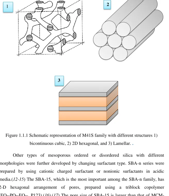
The first examples of mesoporous silica, known as M41S family were reported by Mobil scientists in 1992.(9) In the M41S family, the initial composition of charged cationic surfactant (cetyltrimetyl ammonium bromide (CTAB)) and tetraethylorthoslicate (TEOS) in optimized pH were altered in order to determine the structure of the final material such as hexagonal MCM-41, cubic MCM-48, lamellar MCM-50 as indicated in Figure 1.1.1.(10) Among the M41S family, the most popular one is the MCM-41 with a 2-D hexagonal structure with cylindrical 2-D pores through the particles, and belongs to p6mm space group.(11) The pore size distribution is in the range of 4 to 6 nm with about 1 nm wall thickness leading to higher than 1000 m2g-1 surface area.
3
Figure 1.1.1 Schematic representation of M41S family with different structures 1) bicontinuous cubic, 2) 2D hexagonal, and 3) Lamellar. .
Other types of mesoporous ordered or disordered silica with different morphologies were further developed by changing surfactant type. SBA-n series were prepared by using cationic charged surfactant or nonionic surfactants in acidic media.(12-15) The SBA-15, which is the most important among the SBA-n family, has 2-D hexagonal arrangement of pores, prepared using a triblock copolymer (EO20PO70EO20, P123).(16),(17) The pore size of SBA-15 is larger than that of
MCM-41. In addition, the wall thickness is so thick (around 20 nm) that it provides extra thermal stability. Other members of SBA-n family, SBA-1 and SBA-6 have cubic, mesoporosity synthesized by using charged surfactants under acidic or basic conditions.(18, 19)
1 2
4
1.2 True Liquid Crystal Templating (TLCT) Method
The mesoporous silica particles, like MCM-41 and SBA-15 are synthesized at surfactant concentrations above CMC. However, silica monolith with an ordered pore structure could not be synthesized in dilute conditions. Attard and coworkers introduced, for the first time, a novel method that uses liquid crystalline region of a surfactant and a silica precursor for the synthesis of silica monoliths.(20) They utilized the liquid crystalline phase of nonionic, oligo(ethylene oxide) surfactant of C16H33(OCH2CH2)8OH, (represented as C16EO8)in the presence of a silica precursor.
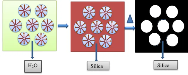
The hydrolyzed silica precursor (tetramethylorthosilicate, TMOS) by acid was impregnated into liquid crystalline phase. After polymerization of hydrolyzed silica precursor and removal of surfactant, a crack-free mesoporous silica monolith with a 2D hexagonal pore structure can be obtained: that is a negative copy of liquid crystalline phase. This method is known as true liquid crystal templating method (TLCT) and is illustrated in the Figure 1.2.1.
Mesoporous silica monoliths with various structures can be obtained via TLCT by altering the liquid crystalline phase with different surfactants, compositions and additives.(21, 22) However, this method always produces thicker films or monoliths.
H2O Silica Silica
Figure 1.2.1: The illustration of true liquid crystalline templating method. The formation of liquid crystalline phase of surfactant (left), inclusion of inorganic precursor to liquid crystal phase (middle), and polymerization of inorganic precursor
5
Therefore a new approach is necessary to investigate the thin film technologies of mesoporous materials. There are many publications on the synthesis of mesoporous silica thin films. (23),(24) The most attractive and widely investigated method is the evaporation induced self-assembly (EISA) that is also applicable to other mesostructured metal oxides.(25)
1.3 Evaporation Induced Self Assembly (EISA) Method
In order to overcome the drawbacks of TLCT method, as mentioned above, Brinker and coworkers have introduced, for the first time, the EISA method providing rapid formation of self-assembly of surfactant and inorganic moiety with a prefect, oriented replica of liquid crystal template.(25) The self-assembly of surfactant and inorganic moiety occurs at the same time and this provides a homogenous distribution of surfactant and inorganic precursors.
A typical phase diagram of a CnEOm-H2O is showed in Figure 1.3.1. Notice that
the surfactant molecules at low concentration form homogenous solution in an aqueous media. Above the CMC, they start to aggregate and to create micelles by the help of attractive (hydrophobic) and repulsive (hydrophilic) domains of surfactant and water. Furthermore, at higher concentration of surfactant and adequate temperature, the liquid crystalline phase with different structures can be formed according to surfactant percentage and temperature, such as cubic, hexagonal and lamellar. (26)
6
Figure 1.3.1: The phase diagram of C12EO8 and water: bicontinuous cubic
(V1), normal hexagonal (H1), micelle cubic (I), micelle (L1). (27)
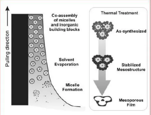
The assembly process starts in a homogenous solution of surfactant and inorganic precursor with large amount of easily volatile solvent having low viscosity. Generally, dip coating of this solution over a substrate produces monoliths (28, 29) or films.(30) The substrate, dipped into above solution is generally pulled upwards with constant rate; the evaporation of volatile solvent starts in the upper parts of substrate.(31) After evaporation of the solvent, a homogenous liquid crystalline phase starts forming on the surface of the substrate with the concentration of surfactant over time, as illustrated in Figure 1.3.2. The inorganic precursor in the LLC mesophase polymerizes and eventually solidifies the film into an ordered organic-inorganic mesostructures, in the aging step. The mesoorder of this liquid crystalline phase depends
7
on the dip coating rate and initial concentration of surfactant and inorganic precursor.(25) The surfactant molecules can be removed from the structure by either calcination or washing with a proper solvent. Moreover, the EISA process can also be operated by spin and spray coating methods.(32) In conclusion, the EISA process is a crucial and facile method for the synthesis of mesoporous silica, and also for some metal oxides thin films.
Figure 1.3.2: The schematic representation of Evoparation Induced Self Assemly (EISA) process.(33)
1.4 Mesoporous Transition Metal Oxides
Perhaps, the most studied and well-understood known mesoporous material is mesoporous silica owing to easy and well-known sol-gel chemistry of silica. However, mesoporous other metal oxides are more attractive than mesoporous silica because of great interest on their applications, as heterogeneous catalysts, photovoltaic devices, sensing, photocatalysts and biological applications.(34-37) Yet, the synthesis of mesoporous metal oxides is quite difficult compared to mesoporous silica. The first
8
difficulty is the reactivity of metal oxide precursor that makes the control of the polymerization step of metal oxide precursor more difficult.(38) In addition, during the calcination process, the pores may collapse due to redox reactions, phase transformation and crystallization. Despite those difficulties, chemists have developed some synthesis protocols to synthesize mesoporous metal oxides.
1.5 The EISA Process for Synthesis of Mesoporous Metal Oxides
The EISA process is also a powerful method for the synthesis of mesoporous films and monoliths. The first examples of mesoporous metal oxides, such as TiO2,
ZrO2, Nb2O5, Ta2O5, Al2O3, SnO2, WO3, HfO2, and mixed oxides SiAlOy, Al2TiOy,
ZrTiOy, SiTiOy, and ZrW2Oy via EISA process, were demonstrated by Stucky and
coworkers.(39, 40) Like the synthesis of mesoporous silica by EISA method, the mesoporous metal oxides were synthesized by using liquid crystalline templating from a dilute solution of surfactant and proper metal oxide precursor in a proper solvent. The EISA of surfactant and metal oxide precursor results a mesostructured solid upon evaporation of the solvent. Obtaining a stable metal oxide solution with a proper solvent is very important. The transition metal chlorides, MCl4, are stable in ethanol in the
presence of hydrochloric acid, due to the formation of stable chloroalkoxy complexes of metals. Fortunately, less reactive metal oxide precursors, like metal alkoxides (M(OR4)),
could be used to better control on the synthesis of mesoporous metal oxides.(41) Co-assembly of metal complexes using pluronics, such as P123 (HO(CH2CH2O)26
-(CH(CH3)CH2O)70-(CH2CH2O)26H, EO26PO70EO26), and provides large pores with
thicker metal oxide walls that can be crystallized upon calcination. Note that smaller surfactants cause the collapse ordered pore system upon calcination. The EISA process of mesoporous metal oxides is schematically represented in Figure 1.5.1.
Slow condensation of metal oxide precursor in the solution is very important to obtain a mesostructured framework. Metal alkoxides, such Ti(OR)4, condenses itself into
titania, TiO2, in an acidic and humid environment. For a better controlled condensation
of metal oxide precursor, bidentate ligands have been used. Bidente ligands such as carboxylate and nitrates are useful in the condensation and crystallization of the precursors owing to the formation of linkage among metal species.
9
Mesoporous ordered metal oxide with large pore
a) Evaporation Induced Self-Assembly Process
Homogenous Solution
Evaporation of alcohol Dip coating
Co-assembly of metal oxide precursor and surfactant
Calcination
Condensation of metal oxide precursor and formation of mesophase
Surfactant
Metal oxide precursor Volatile Solvent
10
The EISA method has been employed by several groups for the synthesis of various mesoporous metal oxides and mixed metal oxides.(42-48) Most of the synthesized mesoporous metal oxides and mixed metal oxides by EISA method are limited to early transition metals (Ti, Ta, Nb, Zr and etc.). Alkoxides of late transition metals (Fe, Ni, Co, Zn, Cd and etc.) with more d electrons are very reactive that makes the EISA method very difficult. The high reactivity results in an uncontrolled condensation and formation of bulk metal oxides. However, some transition metal oxides, such as Fe2O3 (49), CrOx(50) and NiO (51) have been synthesized via EISA
method. In the synthesis of mesoporous Fe2O3 and CrOx , the metal precursors are their
nitrate salts. The nitrate ion can coordinate to metal ion and also bridge two or more metal complexes in non-aqueous solution. This provides a slow condensation of metal precursor to metal oxide framework. However, the EISA method has some drawbacks in the synthesis of mesoporous transition metal oxides; i) since the gelation and
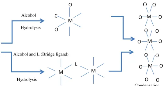
Figure 1.5.1: The schematic representation of EISA for the synthesis of Mesoporous metal oxides; a) the EISA process and b) the stabilization of metal oxide
precursor.
b) The Stabilization of Transition Metal Oxide Precursor (TMO) Condensation
M(OR) 4 + HCl or Alcohol (H O) Hydrolysis M + C l O H O R M + L
Alcohol and L (Bridge ligand)
Hydrolysis Condensation O O O O O O O O O O O O O O M M M M
11
condensation step takes long such as 7- 14 days, it is not a facile method and ii) the crystalline walls are too thick (about 10 nm), causing a decrease in the surface area. 1.6 Nano-casting of Metal Oxides
Nano-casting method is a hard templating method, which is an alternative synthesis protocol for the synthesis of several mesoporous metal oxides with different pore topologies.(52-57) The nano-casting method has been applied for the synthesis of mesoporous metal oxides, as listed in Table 1.6.1.
The type of hard template and pore topology for nano-casting
Mesoporous Metal Oxides
SBA-15, 2-D hexagonal silica (p6mm) CeO2(58-60) Co3O4(61-64), Cr2O3(58, 65-67),Fe2O3(58),MnO2(68, 69),NiO(58)
KIT-6, cubic (Ia3d) silica CeO2(59) (70), Cr2O3(71) (66),
Fe3O4 (72),In2O3 (73)
SBA-16 cubic (Im3;m) silica Co3O4 (74) (58),
In2O3
(58)
2D hexagonal (p6mm) carbon CuO (75), MgO (76), ZnO (77)
Table 1.6-1: The summary of some mesoporous metal oxides via nano-casting The nano-casting synthesis protocol involves three steps: i) inclusion of proper metal oxide precursor into the pores of hard templates, ii) conversion of metal oxide precursor in the mesopores to metal oxide upon calcination under ambient conditions, and iii) removal of the hard template. Common hard templates for the nano-casting route are mesoporous silica (SBA-15 and SBA-16) and mesoporous carbon. Nanocasting process, through using mesoporous silica for the synthesis mesoporous metal oxide, results in inverse replica of the mesoporous silica hard template. This means that the pores of the hard template are filled with the metal oxide during the calcination step and then the silica walls are removed to form mesoporous metal oxides. In SBA-15, the pore
12
structure is 2-D hexagonal and pores are connected to each other with micro channels. Therefore, even after the removal of silica walls, the metal oxide rods are connected to each other via micro rods leading to continuous, bridged metal oxide rods. The SBA-16 has a 3-D cubic pore topology that makes it more appropriate to obtain continuous mesoporous framework after removal of the silica template. Herein, the main trick for the synthesis of mesoporous metal oxide is the choice of mesoporous silica hard templates with thicker walls.
In order to obtain mesoporous metal oxide with true porous topology like in mesoporous silica, a better hard template is mesoporous carbon. The mesoporous carbon can be synthesized via nano-casting by using mesoporous silica (SBA-15). Therefore, the pores of mesoporous silica are filled with carbon, by decomposing carbon species in the pores, then the silica walls are etched out. This provides that the mesoporous metal oxides will have a true mesopore topology like in mesoporous silica after nano-casting step. These two path ways of nano-casting using mesoporous carbon and silica to create mesoporous metal oxides are schematically represented in Figure 1.6.1.
13
A key factor in nano-casting method is impregnation of metal precursor into pores of mesoporous silica with an efficient filling. The metal nitrate salt in a proper Mesoporous Silica SBA-15, SBA-16.. Path 1 Mesoporous Carbon Mesoporous Metal Oxides Path 2 Mesoporous Metal Oxides
Figure 1.6.1: The schematic representation of two different paths of nano-casting for the synthesis of mesoporous metal oxides
14
solvent is mixed well with mesoporous silica and then the solvent is evaporated. However, the impregnation method does not always provide efficient inclusion of metal nitrates into of the mesoporous silica. One strategy for an efficient pore filling uses mesoporous silica, in which the surfactant has been removed using microwaves.(78) The silanol groups on the surface of the pore can be kept during the calcination step and this enhances the filling rate of metal oxide precursor into pores in polar solvent. Another strategy for an efficient pore filling is functionalization of silanol groups with proper chelating ligands. Schüth and coworkers have used 2-dimensional hexagonal SBA-15 silica that is functionalized with vinyl groups for the synthesis of mesoporous Co3O4.(79) Vinyl groups can complex with Co2+ cations and facilitate the successful
impregnation of metal salts into pores of SBA-15. An amino functionalized SBA-15 has also been used for the synthesis of mesoporous Cr2O3 and WxOy by using acidic
solutions of K2Cr2O7 and H3PW12O40, respectively.(65, 66, 80) Another effective
strategy in the literature is usage of molten metal salts without a solvent(74) (metal nitrates generally melt at low temperatures). In all of these strategies, the repetitive loadings is necessary in order to increase loading of metal oxide precursor in the mesopores, however, this may cause undesired formation of bulk metal oxide outside of mesoporous silica.
Despite the fact that a 100 % pore filling cannot be accomplished, after calcination process to convert metal oxide precursor to metal oxide, the metal oxides could not fill all the pores of mesoporous silica. There is a huge density difference between metal oxide precursors and metal oxides. This causes a large volume contraction. The general choice of metal oxide precursor for nanocasting method is metal nitrates. (19) that usually have low decomposition temperature. For example, the melting point of [Zn(NO3)2].6H2O is only 35.5 oC and its density is only 2.065 g/cm3 but
the density of ZnO is quite high, 5.606 g/cm3. If one mole [Zn(NO3)2].6H2O is converted
into one mole ZnO, the volume of zinc salt is decreased to its 10.1% . This means that the voids of mesoporous silica, totally filled with zinc nitrate hexahydrate, will only coat silica surface and only block 10.1% of the pore volume. Some other metal nitrates and their volume contraction are listed in Table 1.6.2. This enormous volume contraction of metal precursor is an important drawback for the synthesis of mesoporous metal oxides
15
through nanocasting method. Therefore, homogenous formation of mesoporous metal oxide over mesoporous silica may become impossible by using mesoporous silica or mesoporous carbon as a hard template. Furthermore, the multiple inclusions of metal oxide precursors into mesoporous silica to increase the degree of filling may not work well because of occlusion of the pores in the previous trials.
Precursor Target material Percentage Of Volume Contraction (%) Fe(NO3)3 9H2O Fe2O3 93.66 Cu(NO3)2 3H2O CuO 87.91 Zn(NO3)2 6H2O ZnO 89.90 Cd(NO3)2 6H2O CdO 87.99 Co(NO3)2 6H2O Co3O4 93.46 Mn(NO3)2 6H2O MnO2 89.23 Cr(NO3)3 9H2O Cr2O3 93.44
Table 1.6-2: The summary of some transition metal nitrates and their volume contraction After the conversion of metal oxide precursor to metal oxide, the removal of hard template, mesoporous silica or mesoporous carbon, is necessary to obtain mesoporous metal oxides. The silica walls can be etched by NaOH or HF solutions.(51, 53, 58, 72,
74) If mesoporous carbon was used as a hard template, the carbon walls can be removed
by calcination at 500-700 oC.(75) However, mesoporous carbon as a hard template may be an advantage for the synthesis of some mesoporous metal oxides, such ZnO(77) and MgO(81), compared to mesoporous silica. Because the HF or NaOH solution etches
16
these kinds of metal oxides due to their amphoteric character, and result a collapse of mesostructure.
In addition, nanocasting method is more applicable for the synthesis of mesoporous metal oxide powders rather than thin films. For the heterogeneous catalysis, it is important to produce large scale mesoporous catalyst with a high surface area.(52,
55) However, many applications, such photovoltaic applications, are based on thin film
technologies.(82, 83)
1.7 Solid State Grinding Method
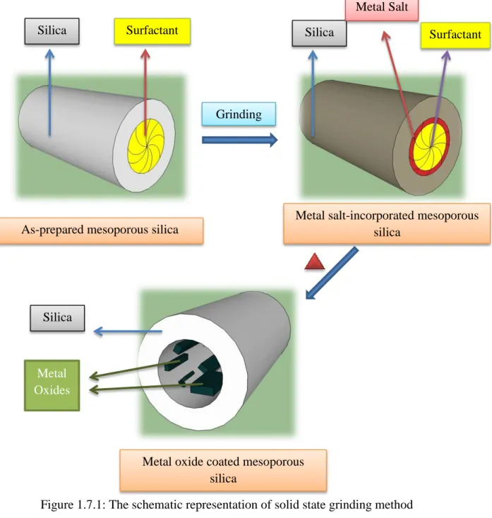
The nanocasting method for the synthesis of mesoporous metal oxides is quite time consuming and contains lots of steps (preparation of hard template, inclusion metal oxide precursor, condensation and template removal). Therefore, elimination of even one step, in nanocasting method, would be a great advantage for the synthesis of mesoporous metal oxides. In addition, the nanocasting method does not produce homogenous and continuous mesoporous frameworks. Wang and coworkers developed a novel method, in which a metal oxide precursor without a solvent is incorporated into the as-prepared mesoporous silica. Calcination results in a homogenous coating of pore surface with the metal oxides and removal of the surfactant.(84) This method has been employed to several metal oxides, such as MgO, CuO and ZnO. (84-88) In general, as-prepared mesoporous silica is grinded together with a metal nitrate salt without a solvent; the metal nitrate salt is incorporated into as-prepared mesoporous silica without any extra drawing force. Presence of surfactants inside the pores prevents the formation of nanorods ; instead formation of nanoparticles covering the surface of silica was enhanced. The schematic representation of solid state grinding method is shown in Figure 17.1.
17
The solid state grinding method is a less time consuming and a facile synthesis method compared to nanocasting method. However, the volume contraction problem still exists as in the nanocasting method and limits the surface coverage of the pores. In addition to this, loading of the metal oxide precursor, metal nitrate, is less than that in nanocasting method. To illustrate, this method has been employed to coat mesoporous SBA-15 with CuO with a coverage of only 15% of the surface of silica walls; authors of this work also mentioned that they observed pore blocking in some parts of mesoporous silica.(84) Therefore, a more efficient loading and conversion method is required to
Silica Surfactant
As-prepared mesoporous silica
Silica Surfactant
Metal Salt
Metal salt-incorporated mesoporous silica
Grinding
Metal oxide coated mesoporous silica
Silica
Metal Oxides
18
enhance the metal oxide loading with a uniform distribution in the pores of mesoporous silica, specifically as thin films for advanced applications.
1.8 Lyotropic Liquid Crystalline (LLC) Mesophases of Transition Metal Salts Liquid crystals are divided into two groups; thermotropic liquid crystals and lyotropic liquid crystals. While thermotropic liquid crystals are a kind of ordered assembly of molecules that shows a phase transformation with temperature change, the phase of lyotropic liquid crystals depends on a second component (solvent) and temperature. By using lyotropic liquid crystalline (LLC) templating method (know as true liquid crystalline templating, TLCT, method), different types of mesoporous materials have been synthesized as mentioned in the previous chapters.
Dag et al. have introduced a new type of LLC mesophase in which the transition metal aqua complexes act as a solvent and form the LLC mesophases with oligo(ethylene oxide) surfactants (C12H25(CH2CH2O)10OH, C12E10).(89) Herein, they
showed that the coordinated water molecules of the transition metal aqua complexes direct the self-assembly of surfactant molecules into hexagonal or cubic mesostructures with the help of hydrogen bonding (between ethylene oxide groups of the surfactant and coordinated water of aqua metal complex). The hexagonal LLC mesophase of [Zn(H2O)6](NO3)2 −C12EO10 is stable up to 70 w/w % (weight of salt over total weight
percent) at RT. A schematic representation of this self-assembly in a hexagonal packing and its characteristic fan texture of hexagonal phase are shown in Figure 1.8.1.
19
Figure 1.8.1: a) A POM image of [Cd(H2O)4](NO3)2 in C12H25(CH2CH2O)10OH and b) a
schematic representation of a hexagonal LLC phase, the small circles represent metal complexes and NO3− ions.(89)
The thermal and structural properties and behaviors of this novel LLC phases have been investigated in detail using different surfactants and transition metal
salts.(90-94) One of the important improvements in the salt-surfactant LLC mesophases is the
addition of a charged surfactant, CTAB or SDS together with C12EO10. This resulted an
increase in the metal salt, [Zn(H2O)6](NO3)2, content, up to 8 metal ion/C12EO10 mole
ratio.(94) The charged surfactants balance the surface charge of the salt species in the hydrophilic domains; as a result, stabilize the mesophase at very high metal ion/C12EO10
20
in Figure 1.8.2.(90) The new mesophase is stable below 0 oC. Moreover, they concluded that the zinc nitrate hexahydrate salt is in the molten phase in confined hydrophilic domains of the LLC mesophase and organize the surfactant molecules into mesophase. This discovery is an important step for both understanding the origin of the salt:surfactant LLC mesophases and designing new materials by using these phases.
Figure 1.8.2: The phase diagram of [Zn(H2O)6](NO3)2 and C12EO10 system:
bicontinuous cubic (V1), normal hexagonal (H1), micelle cubic (I), micelle (L1).(90)
1.9 ZnO Nanoparticles and Mesoporous ZnO
ZnO is a n-type and wide band gap semiconductor with band gap of 3.37 eV and an exciton (e-h pair) binding energy of 60 meV. These properties make ZnO unique in many applications as a piezoelectric materials, UV light-emitting diodes, lasers, photovoltaic solar cells, UV-photodetectors, gas-sensors, and varistors.(95-98) For many applications of ZnO that require high surface area, the synthesis of mesoporous ZnO is
21
also very important.(83, 99) To the best of our knowledge, only one example of mesoporous ZnO prepared by EISA method was demonstrated by Schüth and coworkers.(100, 101) They have used a special organometallic single-source precursor for the controllable condensation of ZnO precursor. The mesoporous ZnO has also been prepared through nanocasting method.(102) Generally, ZnO nanoparticles were embedded into mesoporous silica to obtain high surface area ZnO without particle aggregation through solid state grinding method,(103) templating chelating ligand (104) and functionalization of silica walls (105). However, all these methods do not ensure high loading of zinc oxide into mesoporous silica.
In this thesis, we have developed a novel synthesis protocol for mesoporous silica–metal oxide (ZnO and CdO) thin films. In this method, two surfactants (a charged surfactant, CTAB and C12EO10) with a silica precursor, TMOS assemble together with
an extensive amount of zinc nitrate hexahydrate, [Zn(H2O)6](NO3)2, or cadmium nitrate
tetrahydrate, [Cd(H2O)4](NO3)2, into a liquid crystalline mesophase. The confinement of
the metal salt in mesophase makes the metal salt transform into its molten phase that acts as a solvent and organizes two surfactants into a hexagonal liquid crystalline phase. Then, this mesophase can be converted into mesoporous silica-metal oxide thin films upon calcination. We named this novel synthesis protocol as molten salt assisted self-assembly (MASA) in which two solvents are used: a volatile solvent (water) which provides homogenous mixing of the ingredients into a clear solution and facilitate self-assembly and a non-volatile solvent (metal nitrate salts at molten state) that stabilizes and keeps the mesophase after water evaporation enables for the formation of metal oxide. The MASA synthesis protocol has been investigated by using x-ray diffraction (XRD), Fourier transform infrared (FT-IR) spectroscopy, UV-Visible absorption spectroscopy, Transmission electron microscopy (TEM ), Energy dispersive x-ray spectroscopy (EDS), polarized optical microscopy (POM) and N2 sorption surface area
22 2 EXPERIMENTAL
2.1 MATERIALS
The chemicals which are used throughout this investigation are: zinc nitrate hexahydrate [Zn(H2O)6](NO3)2 (%98 Aldrich) represented as ZnX, cadmium nitrate
tetrahydrate [Cd(H2O)4](NO3)2 (%98 Aldrich) represented as CdY,
tetramethylorthosilicate (TMOS) (%98 Aldrich), cetyltrimethylammonium bromide CTAB, 10-lauryl ether, C12H25(OCH2CH2)10OH, (C12EO10), and deionized water.
2.2 SYNTHESIS
2.2.1 Synthesis of Mesostructured- ZnX Salt-Silica Thin Films
Dissolve a desired amount ofZnX (see Table 2.2.1), 0.291 g CTAB, and 0.500 g C12EO10 in 4.5 ml deionized water in a 25 ml vial by stirring on a magnetic stirrer for 1
day. Then add 0.050 g concentrated HNO3 acid and 0.850 g TMOS to the above mixture
and gently stir the mixture for another 5 min. A solution of 8.0 ZnX/C12EO10 or 1.14
Zn(II)/SiO2 mole ratio contains 1.900 g ZnX, 0.291 g CTAB, 0.500 g C12EO10, 4.500 g
H2O, 0.050g HNO3, and 0.850 g TMOS. Other compositions are given in Table 2.2.1.
Put 1.0 ml of the above solution on a substrate (glass, silicon wafer and/or quartz) over a spin coater and spin it at 1200 rpm for 1.0 min. Make sure the solution completely covers the substrate to ensure full coverage after coating. Put the film sample immediately into an oven at 55 oC for aging 5 minutes.
2.2.2 Fabrication of meso-silica-ZnO-n Thin films
Calcine above thin film from 55 to 450 oC by 1 oC/min increments in a temperature controlled furnace. Remove the film from the furnace prior to slowly cooling the furnace. The film is abbreviated as meso-silica-CdO-n, where n is Zn/Si mole ratio.
23 Sample name
The amounts of Chemicals (g)
ZnX C12EO10 CTAB TMOS HNO3 H2O
meso-silica-ZnO-0.29 0.475 0.500 0.291 1.900 0.050 4.500 meso-silica-ZnO-0.57 0.950 0.500 0.291 1.900 0.050 4.500 meso-silica-ZnO-0.86 1.425 0.500 0.291 1.900 0.050 4.500 meso-silica-ZnO-1.14 1.900 0.500 0.291 1.900 0.050 4.500 meso-silica-ZnO-1.43 2.375 0.500 0.291 1.900 0.050 4.500 meso-silica-ZnO-1.71 2.850 0.500 0.291 1.900 0.050 4.500
24
2.2.3 Synthesis of meso-silica-CdO-n Thin Films
Dissolve a desired amount of [Cd(H2O)4](NO3)2 (see Table 2.2.2), 0.291 g
CTAB, and 0.500 g C12EO10 in 4.5 ml deionized water in a 25 ml vial by stirring on a
magnetic stirrer for 1 day. Then add 0.050 g concentrated HNO3 acid and 0.850 g
TMOS to the above mixture and gently stir the mixture for another 5 min. The sample with 8 CdY/C12EO10 or 1.14 Cd(II)/SiO2 mole ratio contains 1.970 g CdY, 0.291 g
CTAB, 0.500 g C12EO10, 4.500 g H2O, 0.050g HNO3, and 0.850 g TMOS. Other
compositions are given in the Table 2.3.1.
Put 1.0 ml of the above solution on a substrate (glass, silicon wafer and/or quartz) over a spin coater and spin the sample at 1200 rpm for 1.0 min. Make sure the solution completely covers the substrate to ensure full coverage after coating. Put the film sample immediately into an oven at 65 oC for aging.
2.2.4 Fabrication of meso-silica-CdO-n Thin films
Calcine above thin film from 65 to 450 oC by 1 oC/min increments in a temperature controlled furnace. Remove the film from the furnace prior to slowly cooling the furnace. The film is abbreviated as meso-silica-CdO-n, where n is Cd/Si mole ratio.
2.2.5 Etching of meso-silica-CdO-n Thin Films
The calcined films or the powders, scraped from the substrates, were etched in a 4% HF solution in plastic vials. Centrifuge the solution to collect powder by decanting the liquid part into waste bottle. Add distilled water over the precipitate to wash out any remaining fluoride species. Centrifuge the mixture and remove the liquor and repeat the washing step 2 to 3 times. Then dry the powder in an oven.
25 Sample name
The amounts of Chemicals (g)
CdY C12EO10 CTAB TMOS HNO3 H2O
meso-silica-CdO-0.29 0.492 0.500 0.291 1.900 0.050 4.500 meso-silica-CdO-0.57 0.985 0.500 0.291 1.900 0.050 4.500 meso-silica-CdO-0.86 1.478 0.500 0.291 1.900 0.050 4.500 meso-silica-CdO-1.14 1.970 0.500 0.291 1.900 0.050 4.500 meso-silica-CdO-1.43 2.460 0.500 0.291 1.900 0.050 4.500 meso-silica-CdO-1.71 2.956 g 0.500 g 0.291 g 1.900 g 0.050 g 4.500 g
26 2.2.6 Synthesis of meso-silica-CdS-n Thin Films
Place the calcined meso-silica-CdO-n thin film in a vacuum chamber and evacuate the chamber for 2 min. Put 300 torr H2S gas over the meso-silica-CdO-n thin
films for 100 min at room temperature. Then pump out the unreacted excess H2S gas
from the reaction media for 5 min before removing the sample from the reaction chamber. The samples are labelled as meso-silica-CdS-n.
2.2.7 Synthesis of meso-silica-CdSe-n Thin Films
Place the calcined meso-silica-CdO-n thin film in a vacuum chamber and evacuate the chamber for 2 min. Put 300 torr of 5 % H2Se gas (diluted with pure N2 gas)
over the sample for 15 min at RT to obtain meso-TiO2-CdSe thin film. Then transfer the
excess H2Se gas in the reaction chamber over a CuO loaded mesoporous silica for 2 min
to convert the excess H2Se into CuSe nanoparticles. Then, evacuate the unreacted gas by
using a rotary pump for 5 min before removing the sample. The samples are labelled as meso-silica-CdSe-n.
2.3 CHARACTERIZATION
2.3.1 X-Ray Diffraction (XRD)
The XRD patterns of the films of meso-SiO2-ZnX and meso-SiO2-CdY films on
glass microscope slides were recorded by using Rigaku Miniflex diffractometer with a Cu Kα (1.5405 A°) x-rays source operating at 30 kV/15 mA. The fresh samples of
meso-SiO2-ZnX or CdY were monitored at small angles between 1and 5o, 2θ, with 1o/min
scan rate for the investigation of mesostructure. For the high angle measurements approximately 20 films over glass slides were scraped and collected on a XRD sample holder. The high angle XRD patterns were recorded between 10 and 80o, 2θ by using Pananalytical Multi-purpose x-ray diffractometer, equiped with a Cu Kα (1.5405 À)
27 2.3.2 FT-IR Spectroscopy
FT-IR spectra of the meso-SiO2-ZnX and meso-SiO2-CdY films, coated over
single crystal Si(100) wafers, were recorded by using Bruker Tensor 27 model FTIR spectrometer. The spectra were collected in the range of 400 and 4000 cm-1 with a resolution of 4 cm-1 and by collecting 128 scans. The calcination process of the meso-SiO2-ZnX was monitored using homemade temperature controlled (Digi-Sense Cole
Parlmer) sample holder. The calcined samples were diluted using KBr and pressed into KBr pellets for the FT-IR measurements.
2.3.3 UV-Vis Absorption Spectroscopy
The UV-Vis absorption spectra of meso-SiO2-ZnO-n and meso-SiO2-CdO-n thin
films, coated on quartz substrates were collected by using Thermo Scientific Evolution 300/600 UV-Visible spectrometer. The spectra were obtained in the range of 200 and 800 nm with a resolution of 2 nm and 100 nm/min scan rate.
2.3.4 Polarized Electron Microscopy (POM) Images
The POM images of the films, coated on microscope glass substrate were recorded by using ZEISS Axio Scope A1 Polarizing Optical Microscope in transmittance mode with 20X optic lens, between crossed polarizers.
2.3.5 The N2 (77.4 K) Sorption Measurements
The N2 (77.4 K) sorption measurements were carried by using a TriStar 3000
automated gas adsorption analyzer (Micrometrics) in the relative pressure range, P/P0,
from 0.01 to 0.99. The samples of meso-SiO2-ZnO-n and meso-SiO2-CdO-n were
collected from 15-25 films coated on glass microscope slides by scraping with razor blade and the amount of sample were ranged from 10 mg to 20 mg. Surface areas were calculated in the range from 0.05 to 0.3 relative pressure with 5 points. The powder samples were degassed under (~10-2 torr) vacuum for 3 hours at 300 oC in order to remove adsorbed water and volatile species in the pores prior to measurements.
2.3.6 Transmission Electron Microscopy (TEM) Images
The high resolution transmission electron microscope (HRTEM) images were collected by using a FEI Technai G2 F30 at an operating voltage of 200 kV. The
28
calcined films were scraped and ground in a mortar using 5 ml of ethanol for 10 min and dispersed using a sonication for 5 min. One drop of the dispersed ethanol solution was put on a TEM lacey grid and dried over a hot-plate. Then, for further comprehensive analysis of the crystal structure of ZnO and CdO nanoparticles, the images were analyzed by using the software of Digital Micrograph 3.6.5.
2.3.7 Scanning Electron Microscopy (SEM)
Nano-SEM images were recorded using Hitachi HD-2000 STEM in SEM mode. The samples were prepared by dispersing powders over the TEM grids. The SEM images were also recorded by using ZEISS EVOS-40, operated at 15 kV. The samples were prepared on silicon wafers that were attached to aluminum sample holders using conductive carbon adhesive tabs.
29 3 RESULT AND DISCUSSION
3.1 Optimization of the meso-silica-ZnX-n Films
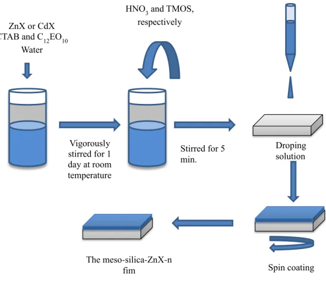
In this thesis, mesostructured salted (ZnX or CdY) silica films were prepared and investigated to synthesize desired mesoporous silica-ZnO or CdO thin films. The meso-silica-ZnX-n films were prepared by spin coating a clear aqueous solution of CTAB, C12EO10, ZnX, HNO3, and TMOS. To obtain the clear aqueous solutions, the
mixture should be vigorously stirred for 1 day. Note that the surfactants, CTAB and C12EO10, which have long hydrophobic tails, are not easy to dissolve (it may take about
1 day) in an aqueous media. After dissolving the surfactants in water, HNO3 and TMOS
are added into the solution (TMOS hydrolyzes to Si(OH)4 by an acid catalyzed
hydrolysis reaction, Equation 3.1.1 and 3.1.2). Note that after addition of TMOS to above acidic solution; the solution warms up, indicating the hydrolysis of TMOS. The hydrolysis follows a condensation step with a pH dependent rate. The condensation of silica precursor in the reaction condition is so moderately high, (Equation 3.1.3) that after 2 hrs from the addition of TMOS and HNO3, the SiO2 nanoparticles are formed.
The solution that is aged for more than 15 min is not good for the synthesis of meso-silica-ZnX-n thin films. Therefore, ideally in 5 min after the addition of TMOS, the solution should be spin coated over a substrate.
Si(OCH3)4 + H2O → HO- Si(OCH3)3+ CH3OH Hydrolysis (Eq 3.1.1)
Si(OCH3)4 + 4 H2O → Si(OH)4 + 4 CH3OH Acid Catalyst Hydrolysis(Eq 3.1.2)
30
In order to prepare the meso-silica-ZnX-n films, the solution of CTAB, C12EO10,
ZnX, HNO3, water, and TMOS is put over a substrate on spin coater and spanned as
represented in Figure 3.1.1. The excess water evaporates during spinning. The film thickness can be adjusted by altering spin rate and time. The ideal spinning rate and time is optimized to be 1200 rpm and 1 min, respectively, for the ideal thickness of meso-silica-ZnX-n thin films. The sample thickness is about 1 µm after the evaporation of water and methanol (a side product).
Vigorously stirred for 1 day at room temperature
HNO3 and TMOS, respectively Stirred for 5 min. Droping solution ZnX or CdX CTAB and C12EO10 Water Spin coating The meso-silica-ZnX-n fim
Figure 3.1.1: The representative preparation of the meso-silica-ZnX-n film by spin coating.
31
The spin coated sample on a glass microscope slide has been characterized using XRD and POM techniques. The as-prepared meso-silica-ZnX-n films are likely in a liquid crystalline mesophase. POM is a useful technique for the determination of anisotropic mesostructures. A fan-like texture, observed from meso-silica-ZnX-1.14 film, under a polarized optical microscope (POM), is characteristic for this existence of 2-D hexagonal mesostructure, see Figure 3.1.2. The observed birefringence in the POM image is characteristic for anisotropic 2-D hexagonal mesophase.
Figure 3.1.2: The POM image of an as-prepared meso-silica-ZnX-1.14 thin film.
32 Figure 3.1.3.
The small angle diffraction lines observed from all compositions of meso-silica-ZnX-n (n is 0.29, 0.57, 0.86, 1.14, 1.43, and 1.71) belong to (100) and (200) planes of 2D hexagonal mesostructure, Figure 3.1.3.a. The d-spacing of the (100) planes, d(100),
x y
z θ=60o
d
(100)a)
b)
a
Figure 3.1.3 a) Small-angle XRD patterns of the as prepared meso-silica-ZnX-n thin films where n is Zn(II)/SiO2 mole ratio(1). b) The schematic representation of d(100) planes in
33
can be calculated by utilizing the Bragg’s law, nλ = 2dsin θ. For example, d(100) for the
meso-silica-ZnX-0.29 is found to be about 4.8 nm, where 2θ is 1.84o. The unit cell parameter, a, is calculated from a = d(100)/sin(60o) (a = 4.8/0.866 = 5.5 nm). The second
line at 3.58o, 2θ, corresponds to the (200) planes of 2D-hexagonal structure. The diffraction lines of meso-silica-ZnX-n, gradually shifts to smaller angles with increasing the ZnX content of the sample. It is reasonable that increase in the salt content in mesostructure increases the unit cell parameter, expands the hydrophilic domains in the mesostructure.
First, for the synthesis of ordered mesoporous silica-ZnO thin film, meso-silica-ZnX-n samples are aged at room temperature for the condensation of silica domains, which eventually provides a rigid 2-D hexagonal and ordered mesostructure. Then, by a controlled calcination under an air atmosphere, the ZnX salt is converted to ZnO and the surfactants are removed. As a consequence, the ordered mesoporous silica-ZnO thin films with 2-D hexagonal structure may be obtained upon calcination.
2 3 4 0 30000 60000 90000 120000 10 20 30 40 0 20000 40000 60000 80000 100000 120000 140000 160000 180000 200000 220000 240000 260000 280000 Time 30 minutes 15 minutes In te n s it y /c p s 2 degree
Figure 3.1.4: Small-angle and wide angle (inset) XRD patterns of the meso-silica-ZnX-1.14 thin films with different aging times where time is shown on the patterns
34
To elucidate and understand the underlying mechanism for the formation of n, the stability of the mesostructure of as prepared meso-silica-ZnX-1.14 thin film was monitored by recording small angle and high angle diffraction patterns at different aging time. The highly intense diffraction line at around 1.4o, 2θ shifts to around 1.8o, 2θ and its intensity decreases after about 2 min, Figure 3.1.4. The diffraction lines at wide angle XRD pattern belong to ZnX salt, Figure 3.1.4 (PDF card number: 00-046-0595). This means that most of the ZnX salt leaches out from the mesostructure and crystalizes out of the 2D hexagonally oriented mesostructure. The shift from 1.4o, 2θ to 1.8o, 2θ, in the low angle diffraction line indicates that domains of the mesophase shrink more than 30%, and likely indication of leaching salt out of the mesostructure.
Figure 3.1.5: Small (top) and wide (bottom) angle XRD patterns of the calcined meso-silica-ZnX-1.14 thin film
If the films, in which ZnX salt leached out from the mesophase, are heated from room temperature (RT) to 450 oC with 1oC /min intervals, the formation of bulk wurtzite ZnO is observed. The diffraction lines in wide-angle XRD pattern of the calcined sample of meso-silica-ZnX-1.14 belong to (100) and (002) planes of wurtzite ZnO (d100 = 2.8141 Å and d002 = 2.6027 Å), Figure 3.1.5. Interestingly, ordered 2-D
hexagonal mesoporous silica-ZnO thin films and bulk ZnO form together. The diffraction line at around 2.4o, 2θ in small-angle diffraction patterns of the calcined
2 3 4 5 0 2000 4000 6000 8000 10000 12000 14000 Inten s it y /cp s 2 degree 20 30 40 50 500 750 1000 (002) Inten s it y /cp s 2 degree (100)
35
sample of meso-silica-ZnX-1.14 originates from the (100) plane of 2-D hexagonal structure (d100 = 3.7 nm), see Figure 3.1.5. Because, all salt species does not leach out
from the mesostructure, remaining ZnX in the mesophase with silica precursor forms the mesoporous ordered structure. As shown in the SEM image of this sample in Figure 3.1.6, after calcination, cracks and round hollows about 1 µm size are formed throughout the film. It is likely that the ZnX salt crystals leached out from the mesophase, formed bulk ZnO crystals. These crystals cover the surface of ordered mesoporous silica-ZnO in which less amount of ZnO than initial salt composition exists in the mesoporous domains of the film.
Figure 3.1.6: The SEM images of calcined the meso-silica-ZnX-1.14 thin film. Inset shows higher resolution SEM image of square.
36 1076 cm -1 NO 3 - symmetric 400 800 1200 1600 2800 3200 3600 4000 0,0 0,6 1,2 1,8 2,4 3,0 CH Free NO 3 0 0.29 0.57 0.86 1.14 A b s o rb a n c e /a .u Wavenumber/cm-1 n 1.43 1 32 6 cm -1 1409 cm-1 147 0 c m -1 1649 cm-1 NO 3 -coordinated H2O H2O 1 0 7 6 cm -1 NO 3 - s y m m etr ic
Figure 3.1.5: The FTIR spectra of meso-silica-ZnX-n ( n is shown on the spectra) (1)
To understand and elucidate the stability issues of the meso-SiO2-ZnX-n thin
films, the FTIR spectra of meso-silica-ZnX-n films (where n is 0.29, 0.57, 0.86, 1.14, and 1.43) are analyzed. The peaks, at around 1326 and 1470 cm-1 in the FTIR spectra of meso-silica-ZnX-n, are assigned to antisymmetric stretching modes of nitrate ions that are coordinated to Zn(II) ion, see Figure 3.1.5. The intensity of these peaks increases with increasing salt content in the samples. At high salt content, the nitrate peaks are very similar to the peaks in molten ZnX salt.(90) Evaporation of water and methanol during spin coating transforms ZnX salt to its molten phase that is confined between the silica clusters and hexagonally organized surfactant domains at high ZnX concentrations. In the as-prepared thin films, the molten ZnX salt acts as a solvent and organizes the surfactant molecules and silica species into mesostructures.


 2 in C 12 H 25 (CH 2 CH 2 O) 10 OH and b) a schematic representation of a hexagonal LLC phase, the small circles represent metal](https://thumb-eu.123doks.com/thumbv2/9libnet/5885841.121610/33.918.302.732.109.654/figure-image-schematic-representation-hexagonal-phase-circles-represent.webp)
 2 and C 12 EO 10 system:](https://thumb-eu.123doks.com/thumbv2/9libnet/5885841.121610/34.918.219.770.284.778/figure-phase-diagram-zn-h-o-c-eo.webp)