ADSORPTION AND DISSOCIATION OF
HYDROGEN MOLECULE ON CARBON
NANOTUBES
a thesis
submitted to the department of physics
and the institute of engineering and science
of b˙ilkent university
in partial fulfillment of the requirements
for the degree of
master of science
By
Yavuz ¨
Ozt¨urk
January, 2004
I certify that I have read this thesis and that in my opinion it is fully adequate, in scope and in quality, as a thesis for the degree of Master of Science.
Prof. Dr. Salim C¸ ıracı (Advisor)
I certify that I have read this thesis and that in my opinion it is fully adequate, in scope and in quality, as a thesis for the degree of Master of Science.
Prof. Dr. Atilla Er¸celebi
I certify that I have read this thesis and that in my opinion it is fully adequate, in scope and in quality, as a thesis for the degree of Master of Science.
Prof. Dr. S¸akir Erko¸c
Approved for the Institute of Engineering and Science:
Prof. Dr. Mehmet B. Baray
Director of the Institute Engineering and Science
ABSTRACT
ADSORPTION AND DISSOCIATION OF HYDROGEN
MOLECULE ON CARBON NANOTUBES
Yavuz ¨Ozt¨urk M.S. in Physics
Supervisor: Prof. Dr. Salim C¸ ıracı January, 2004
Earlier, it has been suggested that carbon nanotubes can provide high storage capacity and other physical properties suitable for the fuel cell technologies. In this thesis we have investigated adsorption, desorption and dissociation of hy-drogen molecule on the surface of the zigzag (8,0) single-wall carbon nanotube (SWNT) by carrying out extensive first-principles pseudopotential plane wave calculations within the Density Functional Theory (DFT). We found that while H2 molecule cannot be bound to the surface of bare SWNT, an elastic radial
deformation leading to the elliptical deformation of the circular cross-section ren-ders the physisorption of the molecule possible. Coadsorption of Li atom on the SWNT makes the similar effect, and hence enhances the physisorption. That an adsorbed H2 can be desorbed upon releasing the elastic radial strain is extremely
convenient for the storage. In addition to that, we found that a Pt atom coad-sorbed on the SWNT can form a strong chemisorption bond with a H2 molecule.
If a single H2 molecule engages in interactions with more than one coadsorbed
Pt atom at its close proximity it dissociates into single H atoms, which, in turn, make Pt-H bonds. The interaction between H2and coadsorbed Pd atom is similar
to Pt, but it is weaker. We believe that these findings clarify earlier controversial results related to the storage of H2 in carbon nanotubes, and makes important
contributions to fuel cell technology.
Keywords: ab initio, first principles, carbon nanotube, density functional theory,
adsorption, binding, hydrogen storage, fuel cell. iii
¨
OZET
KARBON NANOT ¨
UPLER ¨
UZER˙INDE H˙IDROJEN
MOLEK ¨
UL ¨
UN ¨
UN SO ˘
GRULMASI VE AYRIS¸MASI
Yavuz ¨Ozt¨urk Fizik , Y¨uksek Lisans
Tez Y¨oneticsi: Prof. Dr. Salim C¸ ıracı Ocak, 2004
Daha ¨once, karbon nanot¨uplerin yakıt h¨ucresi teknolojileri i¸cin y¨uksek hidrojen depolama kapasitesi ve di˘ger gerekli fiziksel ¨ozellikleri sunabilece˘gi ¨onerilmi¸sti. Bu tezde DFT i¸cerisinde kapsamlı temel-ilke pseudopotansiyel d¨uzlem dalga hesapları y¨ur¨ut¨ulerek; (8,0) zigzag tek-¸ceperli karbon nanot¨upte (SWNT) hidro-jen molek¨ul¨u so˘grulması, ayrılması ve ayrı¸sması incelenmi¸stir. Bulgularımız g¨ostermi¸stir ki, yalın SWNT ¨uzerine H2 molek¨ul¨u ba˘glanamazken, dairesel
ke-sitte eliptik deformasyona sebep olan esnek radyal bir deformasyon bu molek¨ul¨un fiziksel so˘grulmasını m¨umk¨un kılmaktadır. Li atomunun ¨onso˘grulması da ben-zeri bir etkiyle fiziksel so˘grulmayı arttırmaktadır. So˘grulmu¸s bir H2’nin
es-nek radyal baskının kaldırılmasıyla geri kazanılabilmesi depolama a¸cısından son derece ¨onemlidir. Ayrıca SWNT ¨uzerine ¨onso˘grulmu¸s Pt atomunun H2 molek¨ul¨u
ile g¨u¸cl¨u kimyasal ba˘glar yaptı˘gını bulduk. Tek bir H2 molek¨ul¨u birden fazla
¨onso˘grulmu¸s Pt atomunun etki alanına girerse Pt-H ba˘gları olu¸sturan iki H ato-muna ayrı¸smaktadır. H2ile ¨onso˘grulmu¸s Pd atomu arasında da, ¨oncekine nazaran
daha zayıf olmakla beraber, benzer bir etkile¸sim g¨or¨ulm¨u¸st¨ur. Biz bu bulguların karbon nanot¨uplerde hidrojen depolanmasıyla ilgili ¸celi¸sen sonu¸clara a¸cıklık ge-tirece˘gi ve yakıt h¨ucresi teknolojisine ¨onemli katkılarda bulunaca˘gı kanısındayız.
Anahtar s¨ozc¨ukler : ab initio, temel prensipler, karbon nanot¨up, durum
fonksiyonu teorisi, so˘gurulma, ba˘glanma, hidrojen depolarizesı, yakıt h¨ucresi. iv
Acknowledgement
I feel the deepest gratitude and respect to my supervisor, Prof. Dr. Salim C¸ ıracı, for his patience and guidance during my study.
I thank to Prof. Dr. Ekmel ¨Ozbay for his motivation during my undergraduate years.
I also thanks to Dr. Ceyhun Bulutay for his consideration and support.
I always appreciate my family’s ever-existing and never-seizing support and love; my father S¨uleyman ¨Ozt¨urk, my mother Nuran ¨Ozt¨urk, my sister F. G¨ok¸ce G¨o¸cen.
I would like to thank to my companion, my partner, my office-mate and my home-mate Sefaattin Tongay.
I would never forget helps, motivations and company of Sefa Da˘g, Engin Durgun, Ayhan Yurtsever and Deniz C¸ akır.
I will always remember A¸skın Kocaba¸s, Mesut S¸ahin, S¨uleyman Tek and Necmi Bıyıklı.
I also would like to thank to all other friends in the Physics Department.
I will never forget the company of my other home-mates; Nezih T¨urk¸c¨u, Anıl A˘gıral, Cem Ku¸s¸cu, Faik Demir¨ors.
I also would like to mention the names of my two young relatives: my niece K. Nur G¨o¸cen and my nephew K. Alp G¨o¸cen who became a support in my hard times by their very existence.
Contents
1 Introduction 1
1.1 Motivation . . . 1
1.2 Objective of the Thesis . . . 4
1.3 Organization of the Thesis . . . 4
2 Fuel Cells 6 2.1 What is a Fuel Cell? . . . 6
2.2 Types of Fuel Cells . . . 7
2.2.1 Phosphoric Acid Fuel Cells (PAFCs) . . . 7
2.2.2 Proton Exchange Membrane Fuel Cells (PEM cells) . . . . 7
2.2.3 Molten Carbonate Fuel Cells (MCFCs) . . . 8
2.2.4 Solid Oxide Fuel Cells (SOFCs) . . . 8
2.2.5 Alkaline Fuel Cells (AFCs) . . . 8
2.2.6 Direct Methanol Fuel Cells (DMFCs) . . . 9
2.2.7 Zinc Air Fuel Cells (ZAFCs) . . . 9
CONTENTS vii
2.2.8 Protonic Ceramic Fuel Cells . . . 9
3 Carbon Nanotubes 10 3.1 Carbon Atom and Graphite Crystal . . . 12
3.2 The Structure of Carbon Nanotubes . . . 14
3.3 Synthesis of Carbon Nanotubes . . . 17
3.3.1 Arc Discharge . . . 17
3.3.2 Laser Ablation . . . 18
3.3.3 Catalytic Growth . . . 18
3.4 Carbon Nanotubes with H and H2 . . . 18
3.4.1 H + CNT . . . 19
3.4.2 H2 + CNT . . . 20
3.4.3 H2 + Alkali Doped-CNT . . . 21
4 Theoretical Background 22 4.1 The Schr¨odinger Equation . . . 22
4.2 Fundamental Approximations to Scr¨odinger Equation . . . 23
4.2.1 Born-Oppenheimer Approximation . . . 23
4.2.2 Classical Nuclei Approximation . . . 24
4.2.3 Hartree Approximation . . . 25
4.2.4 Hartree-Fock Approximation . . . 26
CONTENTS viii
4.3.1 Thomas-Fermi Theory . . . 27
4.3.2 Hohenberg-Kohn Theorem . . . 27
4.3.3 Kohn-Sham Equations . . . 28
4.3.4 The Local Density Approximation(LDA) . . . 29
4.3.5 Generalized Gradient Approximation (GGA) . . . 30
4.3.6 Periodic Supercells . . . 30
4.3.7 Plane Wave Basis Set . . . 32
4.3.8 Pseudopotential Approximation . . . 33
4.4 Van der Waals Interaction . . . 34
5 Results 36 5.1 Preliminaries . . . 36
5.2 Method of Calculations . . . 38
5.3 Results . . . 40
5.3.1 Chemisorption of H on (8,0) bare and radially deformed SWNT . . . 40
5.3.2 H2 on (8,0) bare and radially deformed SWNT . . . 41
5.3.3 H2 adsorption on Li-doped (8,0) SWNT . . . 46
5.3.4 H2 adsorption on Pt-doped (8,0) SWNT . . . 47
5.3.5 H2 adsorption on Pd-doped (8,0) SWNT . . . 53
List of Figures
1.1 The energy coming from the sun to earth in one year is 130 times greater than the sum of yearly yields of three major energy re-sources; coal, petrol and natural gas . . . 2
1.2 Energy densities for several hydrogen storage technologies [4]. . . 3
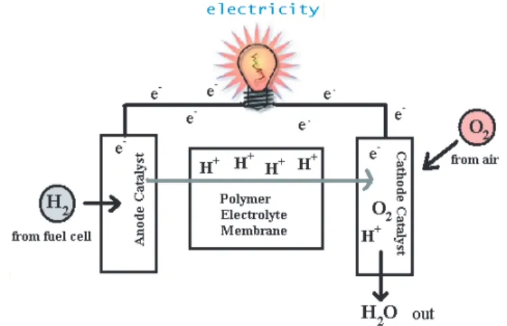
2.1 A schematic description of fuel cell. . . 6
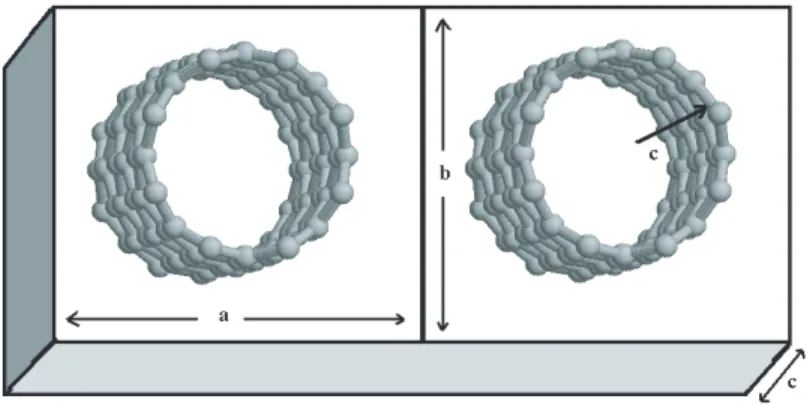
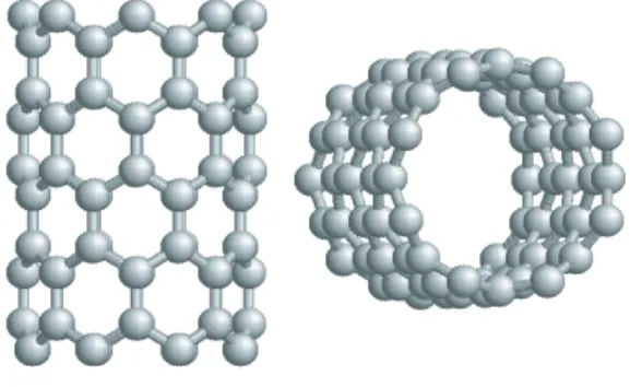
3.1 Carbon nanotubes. . . 11
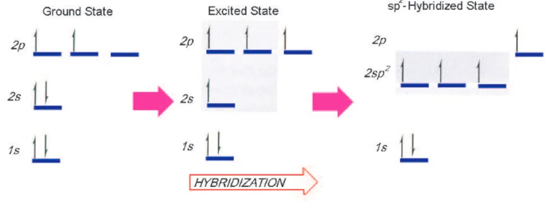
3.2 sp2 hybridization in carbon atom. . . . 12
3.3 Three sp2 hybrid orbitals are coplanar, the unhybridized p
z orbital
is perpendicular to this plane [17]. . . 13
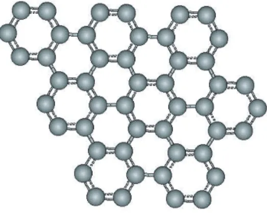
3.4 Hexagonal pattern of a graphene sheet. . . 14
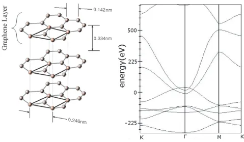
3.5 Graphene layers in graphite lattice are separated by a distance of 0.334 nm. . . 15
3.6 The chiral vector which characterizes SWNTs is linear combination of graphene lattice vectors [12]. . . 16
LIST OF FIGURES x
3.7 Possible vectors specified by (n,m) for zigzag, armchair, and chiral nanotubes. Below (n,m) pairs are listed the number of distinct caps that can be joined continuously to the carbon nanotube denoted by (n,m) [19]. The encircled dots denote metallic nanotubes while the small dots are for semiconducting nanotubes [12]. . . 17
4.1 Supercell geometry for a SWNT molecule. . . 31
4.2 Illustration of all-electron (solid lines) and pseudoelectron (dashed lines) potentials and their corresponding wave functions [47]. . . . 33
5.1 A tiny fuel cell for mobile terminals using carbon nanotubes as electrodes . . . 37
5.2 Band structure and density of states of (8,0) SWNT. Dashed line indicates the Fermi level [67]. . . 37
5.3 The supercell of (8,0) SWNT contains 32 carbon atoms. C-C bond lengths are nearly same as that in graphene, 1.4 ˚A. . . 38
5.4 In one supercell of the (8,0) SWNT there are 8 hexagons. The magnitude of translation vector c is equal to three half of lattice parameter of graphite. That is also three times the C-C bond distance . . . 38
5.5 A schematic description of different adsorption sites of a single H2
molecule on a zigzag (8,0) SWNT. H: hollow; A: axial; Z: zigzag; T: transverse, sites. . . 39
LIST OF FIGURES xi
5.6 (a) Variation of the binding energy Eb of a single hydrogen atom
adsorbed on a (8,0) SWNT as a function of the elliptic radial de-formation, ²r. The upper curve corresponds to H adsorbed on the
high curvature site near the end of the major axis a (sharp site). The lower curve is for the adsorption on the low curvature site at the end of the minor axis (flat site). Insets: Ball and stick models and isosurface plot of difference charge densities, δρ (Reproduced from Ref.[71]). . . 41
5.7 The chemical interaction energy EC, with and without van der
Waals energy as a function of distance d between the surface of undeformed (8,0) SWNT and H2 attached at A-site. The zero
level is the sum of the energy of H2 and bare (8,0) SWNT.The
minimum of EC(d) curve is highlighted by inset. . . . 42
5.8 Density of states of bare and radially deformed (8,0) SWNTs. Zero of energy is set at the Fermi level. Note that the gap is closed for the tube under radial strain. . . 44
5.9 Chemical interaction energy with and without vdW interaction as a function of distance d between the lateral C-C bond and H-H bond at H-site of the (8,0) SWNT radially compressed by ²r = 0.21.
The minimum of EC(d) curve is highlighted by inset. Thick dashed
curve on the left hand side of the graph depicts the path towards dissociative adsorption. . . 45
5.10 The binding geometry of H2 on the external Li-doped (8,0) SWNT. 47
5.11 The two binding geometry of H2 on the internal Li-doped (8,0)
SWNT. . . 47
5.12 The binding geometries of Pt atoms on (8,0) SWNT. (a) Single Pt doping. (b) Double Pt doping. (c) Triple Pt doping. . . 48
5.13 Adsorption configuration of H2 on the single Pt-doped (8,0)
LIST OF FIGURES xii
5.14 H2 molecule is attached to Pt with H-H bond perpendicular to the
axis of (8,0) SWNT(head on). (a) Initial configuration (b) Atomic positions after some relaxion(not fully optimized). . . 50
5.15 H2adsorption on the double Pt-doped (8,0) SWNT is accompanied
by dissociative adsorption. (a)Configuration of H2set initially. (b)
Positions assumed by atoms upon relaxion. . . 51
5.16 The variation of EC(d) as the hydrogen molecule approaches the
double Pt-doped SWNT surface, where d is the distance between H2 and SWNT surface. The peak occurs at d corresponding to
the position of Pt atoms. Note that at the minimum of EC(d)
at d ≈ 1 ˚A, H2 cannot survive but dissociates. Also it can be
deduced that H2 will not suffer a potential barrier since it enters
the chemisorption regime after ≈ 3.9 ˚A. . . 52
5.17 H2 adsorption on triple-Pt-doped (8,0) SWNT.(a) Initial
config-uration of the atoms. (b) The positions after relaxation shows a dissociative adsorption. The bond lengths are also illustrated. . . 53
5.18 The variation of EC(d) as the hydrogen molecule approaches the
triple Pt-doped SWNT surface. The shoulder at d ≈ 2 ˚A cor-responds to the position of adsorbed Pt atoms. The hydrogen molecule enters the chemisorption regime at d ≈ 4 ˚A, so it will suffer a potential barrier of at most 0.1 eV. . . 54
5.19 H2 adsorption geometry on single-Pd-doped (8,0) SWNT . . . 56
5.20 H2 adsorption on double-Pd-doped (8,0) SWNT.(a) Initial
config-uration of the atoms (b) The positions after relaxation indicates a weakening of H-H bond of H2 molecule. . . 56
List of Tables
5.1 Minimum value of the chemical interaction energy EC for four
different sites and the corresponding Van der Waals energy EV dW
at the same distance d between H2 and SWNT. . . 43
5.2 Minimum value of the chemical interaction energy EC for different
sites and corresponding Van der Waals energy, EV dW at the
dis-tance d between H2 and radially deformed SWNT leading to lowest
EC in the first row ²r = 0.21. . . . 45
5.3 The binding energies of successive Pt atoms adsorbed on (8,0) SWNT. . . 48
Chapter 1
Introduction
1.1
Motivation
Energy is among the major issues of today’s society, because of not only its pro-duction and usage, but also its storage and transportation. Today the major source of our energy is fossil fuels; ever increasing use of which is affecting the environment and economy in substantial ways. In order to avoid this growing de-pendence on depleting petroleum sources, alternative clean fuel resources must be resorted. Although there are quite a number of primary energy sources available (such as solar energy, nuclear energy, wind energy, hydropower, plasma, geother-mal energy, etc.), in contrast to the fossil fuels, these new primary energy sources must be converted into fuels in order to be used as fuels for transportation or etc. A new energy carrier is needed. Among the many choices, hydrogen is the best candidate.1
Hydrogen - of which byproduct is nothing else than water - is the cleanest fuel of ever known. It is also easy to produce since it can be analyzed back from water, therefore it is also the cheapest one among other fuels. In addition to that, hydrogen combustion does not contribute to the Greenhouse Effect. In
1For further information see T. N. Veziroglu, Hydrogen energy system as a permanent
solu-tion to global energyenvironmental problems, Chem. Ind. 53: 38393 (1999).
CHAPTER 1. INTRODUCTION 2
fact, converting to a Hydrogen Economy may reverse the Greenhouse Effect. Hydrogen is safer than gasoline or propane, and 14-times lighter than air. If it is freed somehow, it will rise in the atmosphere without causing any danger due to undesired contamination. In contrast to methane and methane derivatives, hydrogen gas is not toxic, thus it is also harmless and desirable from sanitary point of view.
Figure 1.1: The energy coming from the sun to earth in one year is 130 times greater than the sum of yearly yields of three major energy resources; coal, petrol and natural gas.
Hydrogen production is possible via electrolysis of water, the molecule which we have more than everything on the Green Planet via utilization of solar energy. The energy coming from the sun to the earth in each year is 130 times greater than the sum of annual yields of three major energy resources; coal, petrol and natural gas. Harvesting this great amount of cheap energy has been a goal of mankind for years. So nowadays it is not difficult to see corporations dedicated to conversion of solar energy.2
Technologies using hydrogen as an energy source are rapidly being developed. One of the major uses of H2 is in fuel cell vehicles. Fuel cells convert the chemical
energy of hydrogen oxidation directly into electrical energy with emission of only water with very high efficiency since the process is not subject to limitations of Carnot Cycle [1]. This makes development of hydrogen storage and transporta-tion technologies extremely important for the future. The worldwide giants of automotive sector is nowadays on the way to build fuel cell powered vehicles. For instance, Daimler Chrysler Corp. has announced that it would be the first to produce fuel cell cars on the market during the next several years.3
2For instance you may see the website http://www.shec-labs.com 3http://www.daimlerchrysler.com
CHAPTER 1. INTRODUCTION 3
However, hydrogen storage is a major problem because of lack of a safe and efficient onboard storage technology. An ordinary gas tank, which may be carried on a vehicle, will not contain enough amount of hydrogen. Targets for gravimet-ric 6.2 wt.% and volumetgravimet-ric 65% densities for storage and transportation are standardized in the US Department of Energy as a DOE Hydrogen Plan [2]. This standardization is made by considering that a fuel cell powered vehicle would need more than 3.1 kg of hydrogen for running a 500 km range [4]. Up to now no storage technology is capable of reaching the targets (Fig. 1.2).
Figure 1.2: Energy densities for several hydrogen storage technologies [4].
There are four main technologies for hydrogen storage and transportation: compressed gas storage, cryogenic liquid hydrogen storage (liquefaction), metal hydrides, and physisorption [2]. The first three technologies either cannot reach the benchmarks just mentioned, or have significant disadvantages. For exam-ple, compression and liquefaction, are costly, and will surely inflate the total fuel expense. Yet they are far from satisfying the desired goals. Also, liquefac-tion wastes at least one third of the stored energy and liquid hydrogen storage suffers from hydrogen losses due to evaporation. In addition to that carting com-pressed hydrogen gas may cause undesired results, or even catastrophes. The
CHAPTER 1. INTRODUCTION 4
metal hydrides-based technologies suffers from weight and cost concerns.
After the discovery [4] and reproduction [5, 6, 7, 8, 9] of high hydrogen adsorp-tion capacity in carbon nanotubes and other low-dimensional carbon materials, research interest have been casted on carbon based materials, especially carbon nanotubes. If these encouraging experimental results can be reproduced easily and the large-scale production of this carbon materials made available in the near future, it will be possible to reach the DOE hydrogen plan goals.
1.2
Objective of the Thesis
Carbon Nanotubes (CNTs) may serve as the agent for the desired fuel cell tech-nology. Hydrogen storage in CNTs is still at the research level and not yet mature enough for industrial applications. It would be unfair to compare the CNTs for hydrogen storage with that of metal hydrides or other established storage tech-nologies. But it is clear that there is still a long road for CNTs to commercialize.
In this thesis work I will mainly focus on new mechanisms which render CNTs possible media for hydrogen storage. In order to achieve this goal I will first give an outline about the relevant materials, and the current status of research. Later I will discuss our research results and try to explicate the aspects, promising new applications paving the way towards hydrogen storage.
1.3
Organization of the Thesis
This thesis is composed of six chapters:
• (1)Introduction, which offers a general overview on the subject. • (2)Fuel cells, which introduces the fuel-cell concept.
CHAPTER 1. INTRODUCTION 5
• (4)Theory, which provides some theoretical background and indicates
re-quired references for the full theory.
• (5)Discussion of results.
Chapter 2
Fuel Cells
2.1
What is a Fuel Cell?
A fuel cell consists of two electrodes juxtaposed around an electrolyte. Oxygen which is taken from the atmosphere passes over one electrode and hydrogen from the fuel cell over the other. Upon combination, they generate electricity, water and heat. Hydrogen entering the anode of the fuel cell splits into two protons and
Figure 2.1: A schematic description of fuel cell.
two electrons by the existence of a catalyst. After this separation protons pass 6
CHAPTER 2. FUEL CELLS 7
through the electrolyte. Meanwhile, electrons pass through an external circuit creating electricity and return to the cathode to be reunited with the hydrogen and oxygen in a molecule of water.
2.2
Types of Fuel Cells
2.2.1
Phosphoric Acid Fuel Cells (PAFCs)
This type of fuel cell is commercially available today. PAFCs generate electricity at more than 40% efficiency – and nearly 85% of the steam this fuel cell produces can be reused. Operating temperatures are 150 − 200oC. The electrolyte is liquid
phosphoric acid soaked in a matrix. One of the main advantages to this type of fuel cell, besides its nearly 85% cogeneration efficiency, is its usage of impure hydrogen as fuel.
2.2.2
Proton Exchange Membrane Fuel Cells (PEM cells)
This type of fuel cells are also called Solid Polymer Fuel Cells. These cells operate at relatively low temperatures (≈ 80oC) and have high power density. They can
vary their output quickly to meet shifts in power demand. These are very suitable for vehicle applications. The proton exchange membrane is a thin plastic sheet that allows hydrogen ions to pass through it. The membrane is coated on both sides with highly dispersed metal alloy particles (mostly platinum) that are active catalysts. The electrolyte is poly-perflourosulfonic acid, which is a solid organic polymer.
CHAPTER 2. FUEL CELLS 8
2.2.3
Molten Carbonate Fuel Cells (MCFCs)
MCFCs use a liquid solution of lithium, sodium and/or potassium carbonates, soaked in a matrix for an electrolyte. They promise high fuel-to-electricity effi-ciencies, about 60% normally or 85% with cogeneration, and operate at about 650oC. The high operating temperature is an advantage because this implies
higher efficiency and the flexibility to use more types of fuels and inexpensive catalysts. A disadvantage to this, however, is that high temperatures enhance corrosion and lead to the breakdown of cell components.
2.2.4
Solid Oxide Fuel Cells (SOFCs)
Another highly promising fuel cell, this type could be used in big, high-power applications including industrial and large-scale central electricity generating sta-tions. A solid oxide system usually uses a hard ceramic material of solid zirconium oxide and a small amount of ytrria, instead of a liquid electrolyte, allowing op-erating temperatures to reach 1000oC. Power generating efficiencies could reach
60% and 85% with cogeneration.
2.2.5
Alkaline Fuel Cells (AFCs)
These has been used by NASA on space missions. They can achieve power gen-erating efficiencies of up to 70%. Their opgen-erating temperature is 150 to 200oC.
They use an aqueous solution of alkaline potassium hydroxide soaked in a matrix as the electrolyte. This is advantageous because the cathode reaction is faster in the alkaline electrolyte, which means higher performance. They were too costly to commercialize, but several companies are trying to reduce costs and improve operating flexibility.
CHAPTER 2. FUEL CELLS 9
2.2.6
Direct Methanol Fuel Cells (DMFCs)
DMFCs use a polymer membrane as the electrolyte, just like PEM cells. However the anode catalyst itself draws the hydrogen from the liquid methanol, eliminating the need for a fuel reformer. Efficiencies of about 40% are expected with this type of fuel cell. What makes these fuel cells attractive is its operation temperature, that may be typically 50 − 100oC, which makes them appropriate for tiny to
mid-sized applications, to power cellular phones and laptops.
2.2.7
Zinc Air Fuel Cells (ZAFCs)
ZAFCs have a gas diffusion electrode, which is a permeable membrane that al-lows atmospheric oxygen to pass through. After the oxygen has converted into hydroxyl ions and water, the hydroxyl ions will travel through an electrolyte, and reaches the zinc anode. Here, it reacts with the zinc, and forms zinc oxide. This process creates an electrical potential. Due to the abundant amount of zinc on earth, the material costs are low. Hence, zinc-air technology has a potential wide range of applications, There is a current commercialization activity in this field.1
2.2.8
Protonic Ceramic Fuel Cells
This type of fuel cell uses a ceramic electrolyte material that has high protonic conductivity at elevated temperatures. PCFCs on the one hand have the thermal and kinetic advantages of high temperature operation (700oC), on the other hand
they exhibit all of the intrinsic benefits of proton conduction as in PEMs and PAFCs. In addition to that, PCFCs have a solid electrolyte so the membrane cannot dry out as with PEM fuel cells, or liquid can’t leak out as with PAFCs.
For further information you may see Ref.[3].
Chapter 3
Carbon Nanotubes
Carbon nanotubes(CNTs) - long, thin cylinders of carbon - are discovered by S. Iijima in 1991 [10]. These are large macromolecules, and are unique because of their size, shape, and remarkable physical properties. They can be viewed as graphite sheets that are rolled into cylinders. These interesting structures have drawn much attention in recent years and a large amount of research has been dedicated for a better understanding of them. Their physical properties are still being discovered and disputed. Because of their broad range of electronic, ther-mal, and structural properties (defined by its diameter, length, and chirality, or twist), they are considered as promising nanostructures with novel technological applications. Nanotubes are, in fact, either metal or semiconductor depending on their diameter and helicity [11].
The fundamental building block of CNTs is the single-wall carbon nanotube (SWNT). The typical diameter of a SWNT ranges from 0.3 nm to several nm’s. Multi-wall carbon nanotubes (MWNTs) contain several coaxial cylinders of SWNTs with an interlayer spacing of 0.34 − 0.36 nm. Actually SWNTs may be thought as one rolled single layer of graphite. Each end of these cylinders is capped with half of a fullerene molecule [12].
CHAPTER 3. CARBON NANOTUBES 11
Figure 3.1: Carbon nanotubes.
Interest from the research community have first focused on exotic elec-tronic properties of nanotubes. CNTs can be considered as prototypes for one-dimensional quantum wires. They can be used, for instance, in nanoelectronics. Carbon nanotubes also have desirable mechanical properties. Therefore, they can be suitable materials even for strengthening of polymers. They are expected to be the ultimate fiber owing to very high strength-to-weight ratio. Their utility as the strongest or stiffest elements in nanoscale devices or composite materials remains as a powerful motivation. They may also act as nanocontainers since the inner hollow cavity can serve for storage. Hydrogen storage is another field where CNTs may involve. High H2 adsorption data is obtained in some
experi-ments via utilization of CNTs, especially SWNTs, as adsorptive media [4, 8, 9]. An efficient H2 storage technology may unfold the ways to fuel cells of desired
capacity and dimensions. In addition, outer walls of CNTs can be decorated by atoms or molecules for functionalization purposes. Oxygen, hydrogen, aluminum etc. can be used and carbon atoms can be saturated from outside [13]. It is interesting to note that their affinity to make bonds with different atoms may be tuned by radial deformation, which renders them more volatile on the high curvature sites of the outer surface. This kind of deformation is also reversible for CNTs [14]. It is also possible to engineer the band gaps of semiconducting nanotubes or even making them metallic via radial deformation [15]. We may also say that CNTs are exceptional among all one-dimensional systems since they are free from Peierls distortion [16].
CHAPTER 3. CARBON NANOTUBES 12
3.1
Carbon Atom and Graphite Crystal
Being the first member of 4A group, carbon element has a wide range of chemical properties. It involves in many reactions and exists in countless compounds, most of which are central to life. The giant molecules deoxyribonucleic acids (DNAs) that contain all our genetic information are among those. The compounds of car-bon also furnishes the energy that sustains life. Such huge amount of compounds, most of which are related with our very life, urged chemists to reserve a separate branch to the chemistry of carbon the so-called Organic Chemistry. This name referred to compounds that come from a living organism, after 1780s. In those days it was thought that a vital force must intervene for the synthesis of organic compounds. Later on, organic compounds began to be synthesized from sources that were evidently inorganic and the name remained as a memory [17].
Figure 3.2: sp2 hybridization in carbon atom.
Despite this colossal variety of compounds, elemental carbon atoms are found in two different types of crystal structure; namely, (hexagonal) graphite and dia-mond. The 2s and 2p orbitals which are used in the quantum mechanical descrip-tion of the carbon atom are based on hydrogenic wavefuncdescrip-tions. These simple orbitals are inadequate in describing carbon atoms in their compounds such as the
tetravalent-tetrahedral carbon of methane molecule(CH4). The orbital
CHAPTER 3. CARBON NANOTUBES 13
of view this is nothing more than a process that involves the combining of indi-vidual wavefunctions of s and p states to obtain wavefunctions for new orbitals, as described in Fig. 3.2. In graphite, carbon atoms make sp2 hybridization. In
this type of hybridization 2s orbital undergoes a hybridization with two of the 2p orbitals. One 2p orbital is left unhybridized, this is called the pz orbitals as
described in Fig. 3.3 [17].
Figure 3.3: Three sp2 hybrid orbitals are coplanar, the unhybridized p
z orbital is
perpendicular to this plane [17].
In a graphite layer sp2 orbitals of different carbon atoms overlap with each
other and make strong covalent bonds. These bonds are called σ bonds. The overlap of pz orbitals form loose bonds between neighboring layers of graphite.
These bonds are called π-bonds. The geometry of the hybridized orbital is trigonal planar. This is the reason why each carbon atom in graphite structure has three nearest neighbors on the sheets of graphite. This triple bonding results in the fine honeycomb shape of the graphite lattice [18].
A separate layer of graphite is called graphene (Fig. 3.4). Even though each graphene has very strong inlayer bonds due to σ-bonding, they can slide over each other because of weak π-bonding orbitals. The atom-atom distance (or C-C bond) within graphene is 0.142 nm. The distance (or spacing) between two graphene layers if graphite is 2.5 times larger than that value; namely it is 0.334 nm (see Fig. 3.5) [18].
CHAPTER 3. CARBON NANOTUBES 14
Figure 3.4: Hexagonal pattern of a graphene sheet.
3.2
The Structure of Carbon Nanotubes
High resolution microscopy techniques have been used to investigate the structure of CNTs. Graphite wrapped into cylinders form these tiny but as if magical structures. If only a graphene layer is rolled up, the result is a SWNT. SWNTs are named according to their characteristic rolling vector, the so-called chiral vector C, which is defined in terms of graphene lattice vectors a1 and a2. For
specifying the structure of an individual SWNT, an integer pair (n, m) -called chiral indices- are introduced. The diameter and helicity of a defect-free SWNT are uniquely characterized by this chiral vector, C = na1+ ma2, which connects
the crystallographically equivalent sites on graphene [12].
Since the graphene sheet is wrapped by joining the tip and the start of the chiral vector, the length of C is also the circumference of this SWNT. The radius of the tube, R, is given by:
R = |C| π = a 2 √ n2+ m2+ nm (3.1)
CHAPTER 3. CARBON NANOTUBES 15
Figure 3.5: Graphene layers in graphite lattice are separated by a distance of 0.334 nm.
The angle between C and a1 is the chiral angle. If θ = 0o, this SWNT is called
a zigzag nanotube, when a zigzag pattern perpendicular to the axis of the tube is occurred. If θ = 30o it is called an armchair nanotube where zigzag pattern is
parallel to the axis of the tube. If the chiral angle is between these two values, the SWNT is called a chiral nanotube (Fig. 3.6, Fig. 3.7). Any other value of the chiral angle, θ greater than 30o can be folded into this interval.
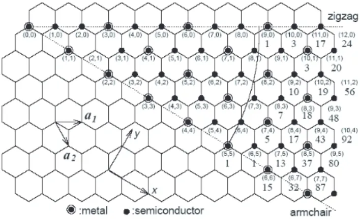
Band calculations predict that chiral indices determine the electronic behavior of SWNTs which may behave either as metallic or as semiconducting [19, 20, 21]. A nanotube having indices (n,m), will be metallic whenever 2n + m sum is an integral multiple of 3. Therefore armchair nanotubes are all metallic. If the curvature effects are neglected the electronic structure of nanotubes can be determined by folding graphene bands. The allowed electronic states of SWNT are then those of graphene that satisfy the circumferential periodic boundary condition: k · C = 2πl, where l is an integer. That is why we see nanotubes either as metals or as semiconductors. Since Fermi surface of graphene is around the corners of hexagonal Brillouin zone, the position of the Fermi vector kF with
respect to chiral vector C will determine the behavior of SWNT. If kF·C = 2πm,
CHAPTER 3. CARBON NANOTUBES 16
Figure 3.6: The chiral vector which characterizes SWNTs is linear combination of graphene lattice vectors [12].
semiconducting [12].
For a one-dimensional metal it is energetically favorable to rearrange the atomic positions. By this way, electrons set up a charge density wave that is a modulation of electronic charge density caused by instability of metallic Fermi surface. That involves the electron-phonon interaction, and results in energy gaps at Fermi level, and gain in electronic energy. At low temperature, the elastic en-ergy cost of lattice distortion is less than the electronic enen-ergy gain so the charge density state is the ground state. At high temperature, the electronic energy gain is reduced by thermal excitation of electrons across the gap, so the metal-lic state is stable. The idea of a single molecule in metalmetal-lic state is then very unusual because of Peierls instability [16]. However, CNT can be an exception because the energy cost of simultaneously rearranging the positions of all carbon atoms is large due to the tubular structure and the gain is small since there are only two subbands near the Fermi level. Hence, the nanotube molecule can be in metallic state. In fact, the mean field transition temperature from the Peierls distorted regime to high temperature metallic regime was estimated well below room temperature [12].
CHAPTER 3. CARBON NANOTUBES 17
Figure 3.7: Possible vectors specified by (n,m) for zigzag, armchair, and chiral nanotubes. Below (n,m) pairs are listed the number of distinct caps that can be joined continuously to the carbon nanotube denoted by (n,m) [19]. The encir-cled dots denote metallic nanotubes while the small dots are for semiconducting nanotubes [12].
3.3
Synthesis of Carbon Nanotubes
3.3.1
Arc Discharge
The arc discharge was the first available method for the production of both MWNTs and SWNTs. It is interesting that this technique has been long used for carbon fiber production. It is probable that nanotubes were already there before 1991, but it was Iijima who first recognized them. MWNTs can be produced in a carbon arc apparatus similar to the one depicted below using the method described by Ebbesen and Ajayan [22]. An arc is applied between two graphite electrodes in a gas atmosphere. MWNTs, produced by arc discharge are long and straight tubes closed at both ends with graphitic walls. Iijima et al. [23] and Bethune et al. [24] reported in 1993 that an arc discharge with a cathode con-taining metal catalysts (such as cobalt, iron or nickel) mixed to graphite powder results in a deposit containing SWNTs. SWNTs are usually assembled in ropes but some single tubes can also be found in the deposits.
CHAPTER 3. CARBON NANOTUBES 18
3.3.2
Laser Ablation
Another method to grow SWNTs is laser ablation which was demonstrated in 1996 by Smalley’s group and has prompted a lot of interest [25]. Thess et al. [26] showed that the synthesis could be carried out in a horizontal flow tube under a flow of inert gas at controlled pressure. In this set-up the flow tube is heated to 1200oC
by a tube furnace. Laser pulses enter the tube and strike a target consisting of a mixture of graphite and a metal catalyst such as Co or Ni. SWNTs condense from the laser vaporization plume and are deposited on a collector outside the furnace zone.
3.3.3
Catalytic Growth
Catalytic growth is another alternative to the arc discharge and laser ablation methods in nanotube production. This method is based on the decomposition of a hydrocarbon gas over a transition metal to grow nanotubes in a chemical vapor deposition (CVD) reactor. Carbon filaments and fibers have been produced by thermal decomposition of hydrocarbons since 1960s. Usually, a catalyst is necessary to promote the growth. It was first used in 1993 by Yacaman et al. [27] to grow MWNTs from the decomposition of acetylene over iron particles. For the production of MWNTs acetylene is usually used as source of carbon atoms at temperatures typically between 600 − 800oC. To grow SWNTs the temperature
has to be significantly higher (900 − 1200oC) due to the fact that they have a
higher energy of formation. In this case carbon monoxide or methane must be used because of their increased stability at higher temperatures as compared to acetylene [28].
3.4
Carbon Nanotubes with H and H
2As indicated before, hydrogen is the key for a possible fuel cell technology. If a suitable mechanism, in which hydrogen is stored and extracted easily, is invented,
CHAPTER 3. CARBON NANOTUBES 19
a major hindrance would be surpassed. It has been contemplated that an efficient, cheap and rechargeable storage mechanism in fuel cells may be provided by CNTs via utilization of their unusual electronic and mechanical behaviors. By this motivation there have been several studies in order to reveal the interactions between atomic H, H2 and CNTs.
3.4.1
H + CNT
Atomic hydrogen is adsorbed on graphene sheet without suffering any potential barrier. Its adsorption on CNTs on the outer surface is even easier. Interaction of atomic H with CNTs has been investigated several times by different groups. Bauschlicher [29, 30] and Froudakis [31] studied the bonding of H atoms on the exterior wall of different SWNT structures. Bauschlicher found the average CH bond energy for the first H to be 0.94 eV, and 1.76 eV for the first two H atoms. The average bond energy for 50% coverage was 2.49 eV, decreasing to 1.68 eV for 100% coverage. Froudakis studied the bonding of single H with the tube where the H atom approached the tube wall in two ways: direct approach to the top of a carbon atom, and approach along the centerline of a hexagon. The energy minima were, respectively, 0.91 eV and 2.43 eV [31].
G¨ulseren et al. have also pursued dedicated studies on exohydrogenation of SWNTs and its effects on electronic behavior of SWNTs [32]. They have found that hybridization of a single carbon atom on SWNT molecule via hydrogenation is always exothermic regardless of the tube radius. Also it is remarkable that hybridization of zigzag nanotubes is more favorable than armchair nanotubes of same radius. This suggests a selective chemical functionalization [13]. By the utilization of band gap engineering on SWNTs, different multiple structures may be combined on a single molecule. Consequently a one-molecule transistor may be constructed out of SWNTs. G¨ulseren et al. [32] also assert that the very high density of states at the Fermi level of uniform pattern isomer at half coverage may yield superconductivity in SWNT based nanowires.
CHAPTER 3. CARBON NANOTUBES 20
been investigated by Lee et al. [33] and Ma et al. [34]. It is evident that atomic hydrogen is not adsorbed from inside the tube due to inversely twisted bonds which makes hybridization harder than flat graphite surface.
3.4.2
H
2+ CNT
Dillon et al. [4] have pioneered the idea that CNTs open the way to the novel fuel cell technology. They have estimated an H2 adsorption of 5-10 weight percent
(wp) for single-wall carbon nanotubes (SWNTs) at pressures less than one bar in ambient temperature. Several recent attempts have justified their estimation by presenting evidence that CNTs can be suitable for hydrogen storage. In fact, Ye et
al. [8] and Dresselhaus et al. [9] came up with H2-storage capacities of 8.25 wp and
4.2 wp, respectively. Unfortunately, studies so far have come up with controversial conclusions. On one side, there have been some theoretical [33, 34, 35, 36] and experimental [6, 37] studies which also support the idea that CNTs can make high H2-uptake possible. For instance, Monte Carlo simulations usually predict high
H2-uptake [35, 36]. On the other side, some other theoretical [38, 39, 40, 41] and
experimental [38, 43] studies have contradicted the data favoring high H2-uptake.
Recently in our own study we have shown that the promising data [4, 8] for bare SWNT are, in fact, exaggerated. These are experimental studies and it is probable that the researchers have mistaken due to some contaminations. In our DFT calculations, we have seen that a bare (8,0) SWNT is inert to H2. Besides
there is a repulsive interaction which avoids them from coming together. On the other hand, whenever the hydrogen molecule is located very near to carbons (∼ 1.1˚A), it is trapped in a local minimum. Surprisingly, when SWNT suffers a
radial deformation it becomes more volatile on the outer surface [14]. So radially deformed SWNTs may indeed adsorb H2 via dissociation. This may be the clue
CHAPTER 3. CARBON NANOTUBES 21
3.4.3
H
2+ Alkali Doped-CNT
Chen et al. [6] demonstrated that alkali metals can serve as catalysts for CNT-H2
reaction. Their results [6] reached up to 20 wp at ambient pressure after the exposure of Li-doped carbon nanotubes to H2 gas at 653 K. Later, some groups
confirmed this result in their own studies [44, 45]. It has been argued that since alkali metals, especially Li, are good electron donors, they decrease the adsorption barrier for molecular hydrogen to disassociate. In our own calculations we were able to see that H2 adsorption on Li-doped (8,0) SWNT is, in fact, enhanced.
Actually it creates a similar effect as radial deformation.
A reversible H2 adsorption mechanism is suggested by Lee et al. [45]. They
claimed that H2 can be extracted from LiH doped SWNTs. Moreover, based on
semiempirical calculations, Dubot and Cenedese [44] claimed that coadsorbed Li allows molecular adsorption of hydrogen on the tube with a binding energy in the chemisorption regime [44]. Despite all these optimistic comments, Yang [46] argued that water contamination in the sample is confused with H2-uptake.
Chapter 4
Theoretical Background
4.1
The Schr¨
odinger Equation
In his correspondence with Einstein, Schr¨odinger wrote,
“ I have been intensely concerned these days with Louis de Broglie’s ingenious theory. It is extraordinarily exciting, but still has some very grave difficulties ”
just a few weeks before publishing his series of six papers on Wave
Mechan-ics in 1926, where he declared his celebrated equation, the so-called Schr¨odinger Equation.
b
HΨi(r, R) = EiΨi(r, R) (4.1)
It is hard to believe that this equation contains all the information of any system via expressing them by many-body wave functions, which can be generally written down as:
b
H = bHel+ bHion+ bHel−ion (4.2)
in terms of electronic Hamiltonian bHel, ionic Hamiltonian bHion and electron ion
interaction, bHel−ion. Explicit forms are as follows:
CHAPTER 4. THEORETICAL BACKGROUND 23 b Hel = − n X i=1 ~2 2m∇ 2 i + e2 2 n X i=1 n X j6=i 1 |ri− rj| (4.3) b Hion = − P X I=1 ~2 2MI ∇2I+e 2 2 P X I=1 P X J6=I ZIZJ |RI− RJ| (4.4) b Hel−ion= −e2 P X I=1 n X i=1 ZI |RI− ri| (4.5)
where R = RI, I = 1, ....P , is a set of P nuclear coordinates, and r = ri, i = 1, ...n, is a set of n electronic coordinates.
If one could have solved the quantum mechanical many-body Schr¨odinger equation of any system, the physical and chemical properties of molecules or even macroscopic bodies would be all in our hands. But as one may expect, analytical solutions exist only in a few cases, such as free electron gas or hydrogen atom. Obtaining the exact numerical solutions is a formidable task which can only be carried out and is only meaningful for systems of very small number of parti-cles [?]. We are dealing with 3P +3n coupled equations. Calculations in the liter-ature predominantly resort to the adiabatic approximation (Born-Oppenheimer) and to the classical treatment of the nuclei [47], which may be accepted as the first two steps on the way to a solution. The other early and important approx-imations which opened the way to Density Functional Theory are Hartree and Hartree-Fock approximations.
4.2
Fundamental Approximations to Scr¨
odinger
Equation
4.2.1
Born-Oppenheimer Approximation
Due to their minute translational inertia - which is one 1836th of that of a proton
CHAPTER 4. THEORETICAL BACKGROUND 24
protons. It will not be a mistake if we say that electrons instantaneously follow the sluggish nuclei. Then without much error, we can separate the movement of electrons and nuclei, and assume that the movement of electrons depends on positions of nuclei in a parametric way. This is the contents of the Born-Oppenheimer approximation. Thus electron remains in the same stationary state all the time [48]. This stationary state will vary in time due to Coulombic in-teraction with the nuclei and electrons will not make transitions between states unless there exist an external effect due to an electromagnetic field.
Born-Oppenheimer approximation gives us the freedom to take the ionic co-ordinates (RI’s) as constants, by taking RI’s as the equilibrium positions, one
obtains the many body electronic Hamiltonian.
b H = − n X i=1 ~2 2m∇ 2 i + e2 n X i=1 Ã P X I=1 −ZI |ri− RI| ! | {z } Vi +e 2 2 n X i=1 n X j6=i 1 |ri − rj| (4.6)
where the second term is the ionic potential.
4.2.2
Classical Nuclei Approximation
In a large variety of systems the solution to the quantum nuclear equation becomes redundant. Nuclear wave functions may be replaced by Dirac-δ functions; if inter-atomic distances are much larger than thermal wavelength in order not to suffer quantum phase coherence, and if the potential energy surfaces in bonding environments are stiff enough so as to localize the nuclear wave functions. As the atomic mass assumes higher values the thermal wave length approximation becomes more and more powerful. Nevertheless, one may easily claim that it is also a very good one in the worse case, i.e hydrogen atom of which interatomic distance is ten times of the thermal wavelength at the room temperature (λT ≈
0.1 ˚A). The connection between quantum and classical regimes can be achieved via Ehrenfest’s theorem which considers the mean values of the position and
CHAPTER 4. THEORETICAL BACKGROUND 25
momentum operators [49].
4.2.3
Hartree Approximation
The motion of electrons are coupled due to electron-electron repulsion expressed by the last term in Eq. (4.6). This way the coordinates in many-electron Hamil-tonian cannot be separated. In 1928 Douglas Rayner Hartree proposed an ap-proximation, which basically proposes that the many-electron wave function can be expressed as multiplication of separate one-electron wave functions [50].
Φ(R, r) = Πiϕ(ri) (4.7)
The effective potential seen by a single electron in Eq. (4.8)is approximated to arise from a charge distribution, which is calculated by absolute squaring the wave function of the other electrons, in Eq. (4.9).
(−~ 2 2m∇ 2+ V(i) ef f(R, r))ϕi(r) = ²iϕi(r) (4.8) with Vef f(i)(R, r) = V (R, r) + Z Pn j6=iρj(r 0 ) |r − r0 | dr 0 (4.9) where ρj(r) = |ϕj(r)|2 (4.10)
is the electronic density associated with particle j. The ²i is the energy of the i-th electron. In practice, we start with some approximate orbitals ϕi (e.g., from
hydrogen atom). We solve all N equations and obtain the N new ϕ0i’s by iterating them until the self consistency is obtained. Then we find the new orbitals and from these orbitals we can form a many electron wave function Ψ, and then calculate the total energy E of the ground state. This process is called
self-consistent field Hartree approximation. It should be noted that the energy of the
many-body system is not the sum of the eigenvalues of the Eq. (4.9) because of the double counting of electron-electron interaction [51]. The total correct energy expression is: E = n X i εn− 1 2 Z Z ρ(r)ρ(r0) |r − r0 | drdr 0 (4.11)
CHAPTER 4. THEORETICAL BACKGROUND 26
4.2.4
Hartree-Fock Approximation
The idea of single-electron approximation is quite good, and allows us to produce an approximate many-electron function for the whole atom. But the form of the function adopted by Hartree was basically wrong and gives rise to incorrect results, since it disregards the fermionic nature of electrons. The wave function shall be in compliance with Pauli exclusion principle. Few years later in 1930 -Fock, and independently Slater proposed an amelioration for the Hartree method. They also used one-electron functions, but the total wave function for the system was not a simple product of orbitals, but an antisymmetrized sum of all the products. It is represented as a determinant (called Slater determinant):
Ψ(R, r) = √1 N! φ1(r1) . . . φ1(rN) ... . .. ... φN(r1) . . . φN(rN) (4.12)
By this function particle exchange is introduced in an exact way [52, 53]. The exchange integral introduces an extra term due to coupling in the Schr¨odinger equation it takes the form:
µ −~2 2m∇ 2 + V (r) ¶ ϕj(r) + e2 X k6=j Z |ϕk(r 0 )|2 |r − r0 | dr 0 ϕj(r) (4.13) +e2 X k 6= j spink Z ϕ∗ k(r 0 )ϕj(r 0 |r − r0 | dr 0 ϕk(r) = Ejϕj(r)
This is the Hartree-Fock equation. The last term in Eq. (4.13) is the non-local exchange potential. Defining the charge density (ρH
j ) and exchange charge
density (ρHF j ) operators as following. Z ρH j dr = −e (4.14) Z ρHj dr = −e X k spink ϕ∗ k(r 0 )ϕj(r 0 ϕ∗ j(r)ϕk(r ϕ∗ j(r)ϕj(r (4.15)
CHAPTER 4. THEORETICAL BACKGROUND 27
We may write the Hartree-Fock equation as follows:
" −~ 2 2m∇ 2 + V (r − e Z ρ(r0 ) − ρHF j (r 0 ) |r − r0 | dr 0 # | {z } F ock Operator ϕj(r) = Ejϕj(r) (4.16)
The solution to this equation involves iteration as in the case of Hartree equa-tion, where you begin with some ad-hoc trial functions. Nevertheless a further difficulty appears because the third term in Eq. (4.16) depends on j, so that Hartree-Fock equation for each electron differs. This can be circumvented by
Slater’s approximation which averages the ρHF
j over all j. So we substitute ρHFj
for ρHF
j in Eq. (4.16). In this way the interaction term becomes only a function
of r, which can be combined with the second term to represent a local potential field which is equally valid for all electrons. This way, one achieves the splitting of the Schr¨odinger equation into one electron equations [51].
4.3
Density-Functional Theory
4.3.1
Thomas-Fermi Theory
Thomas and Fermi proposed that the full electronic density is the fundamental variable of the many-electron problem. They derived a differential equation for density without using the one-electron orbitals [54, 55]. Although it is rather crude the Thomas-Fermi approximation became the starting point for
Density-Functional Theory.
4.3.2
Hohenberg-Kohn Theorem
The use of electron density as a fundamental description of the system was based on intuition rather than rigorous proof, for many years. Electron density depends
CHAPTER 4. THEORETICAL BACKGROUND 28
only on three coordinates1, where as the many-body wave function depends on
all coordinates of all particles. The fact that the ground state properties are functionals of the electron density ρ(r) was proved by Hohenberg and Kohn (1964) and it provides the basic framework for modern Density Functional methods [56]. Two theorems proved by them are:
I. For a non-degenerate ground state of the system the external potential is univocally determined, within a trivial additive constant, as a functional of the electronic density.
That is every observable of a stationary quantum mechanical system (in-cluding energy), can be calculated, in principle exactly, from the ground-state density alone.
II. The ground state density can be calculated, in principle exactly, using the variational method involving only density.
The original theorems refer to stationary ground state, but are being extended to excited states and time-dependent potentials (for further information you may refer to Ref.[57]).
These two theorems construct the framework of the DFT method.
4.3.3
Kohn-Sham Equations
The major error in the Thomas-Fermi approach comes from approximating the kinetic energy as a density functional. On the other hand the kinetic energy operator is non-local even if it is short-ranged. A major advance in this area is provided by W. Kohn and L. Sham in 1965, who proposed the idea of replacing the kinetic energy of the interacting electrons with that of an equivalent non-interacting system [58]. The density matrix ρs(r, r
0
) that for the interacting ground state is the sum of the spin-up and spin-down density matrices. For
CHAPTER 4. THEORETICAL BACKGROUND 29
either spin-up (s = 1)and spin-down (s = 2) we may write:
ρs(r, r 0 ) = ∞ X i=1
ni,sϕi,s(r)ϕ∗i,s(r
0
) (4.17)
The kinetic energy can be written in atomic units (~ = 1, m = 1 and e2 = 1)
exactly as T = 2 X s=1 ∞ X i=1 ni,shϕi,s ¯ ¯ ¯ ¯−∇ 2 2 ¯ ¯ ¯ ¯ ϕi,si (4.18)
For the non-interacting electrons these reduce to.
ρ(r) = 2 X i=1 Ns X i=1 |ϕi,s(r)|2 (4.19) TR[ρ] = 2 X s=1 Ns X i=1 ni,shϕi,s ¯ ¯ ¯ ¯−∇ 2 2 ¯ ¯ ¯ ¯ ϕi,si (4.20)
Using TR[ρ], the universal density functional can be rewritten as follows:
F [ρ] = TR[ρ] + 1 2 Z Z ρ(r)ρ(r0) |r − r0| drdr 0+ E XC[ρ] (4.21)
Here the exchange and correlation energy enters as a functional of the density. Finally the Kohn-Sham functional is:
EKS[ρ] = TR[ρ] + Z ρ(r)v(r)dr +1 2 Z Z ρ(r)ρ(r0) |r − r0| drdr 0+ E XC[ρ] (4.22)
By doing this the density functional is expressed in terms of Kohn-Sham orbitals which minimize the kinetic energy under preset constrain of density [47].
4.3.4
The Local Density Approximation(LDA)
The simplest way to implement density functional approximation is a local ap-proximation, in which the functional is a simple integral over a function of the density at each point in space:
Eloc XC[ρ] =
Z
CHAPTER 4. THEORETICAL BACKGROUND 30
where f (ρ(r)) is a function of charge density, ρ [59].
The LDA is often surprisingly accurate and for systems with slowly varying charge densities generally gives very good results. For atoms and molecules, the total exchange energy is typically underestimated by about 10%. On the other hand, the correlation energy is overestimated by about a factor of 2 or 3 [47]. In some cases, some semiconductors have no gap in LDA, so it makes the incorrect prediction that they are metals [60]. For atomization energies of molecules or cohesive energies of solids, LDA tends to overbind. The bond lengths are predicted fairly accurately by using LDA [47].
4.3.5
Generalized Gradient Approximation (GGA)
In order to correct the insufficient results of LDA, some new computational ap-proaches should be introduced. The most favored way is to introduce semi-locally the inhomogeneities of the density, by expanding EXC[ρ] as a series in terms of
the density and its gradients.
EXC[ρ] =
Z
Axc[ρ]ρ(r)4/3dr +
Z
CXC[ρ]|∇ρ(r)|2/ρ(r)4/3dr + ... (4.24)
This approximation is the GGA and its basic idea is to express the exchange-correlation energy in the following form:
EXC[ρ] =
Z
ρ(r)²XC[ρ(r)]dr +
Z
FXC[ρ(r, ∇ρ(r))]dr (4.25)
where the function FXC is asked to satisfy the formal conditions [61].
Being a more sophisticated approach GGA provides improved binding and atomic energies. Beyond this bond lengths and bond angles are better than that obtained by LDA.
4.3.6
Periodic Supercells
All these formalisms give us the opportunity of transforming the observables of many-body systems into single particle equivalents. Nevertheless, there are two
CHAPTER 4. THEORETICAL BACKGROUND 31
Figure 4.1: Supercell geometry for a SWNT molecule.
difficulties: First of all, for each electron of the system a wave function must be calculated, since each electronic wave function extends over the entire solid. Secondly, for expanding each wave function a basis set of infinite elements is re-quired. If we consider our system as periodic both problems can be circumvented via Bloch’s Theorem [47]. Bloch’s Theorem states that in a periodic system each electronic wave function can be written as a product of two functions: a plane wave exp(ik·r) times a periodic function un,k(r) with the periodicity of the crystal
lattice,
ϕn,k(r) = eik·run,k(r) (4.26)
Using Bloch function, single electron states can be expressed in momentum space. A single molecule is described by a periodically repeating supercells in order to express Bloch function in terms of plane waves in momentum space. These methods for periodic systems may be valid also for non-periodic systems. This can be a single molecule or even a system with a single defect. Of course, since their periods are infinite in principle, a continuous plane-wave basis set would be required. If one uses periodic supercells, calculations using plane-wave basis sets become possible. Supercells and hence crystal structure are generated through out the space by applying periodicity as depicted in Fig. 4.1. In these kind of systems a large enough supercell should be constructed in order to avoid interactions between molecules [47].
CHAPTER 4. THEORETICAL BACKGROUND 32
4.3.7
Plane Wave Basis Set
The Bloch states are expressed in terms of the linear combination of plane waves
ϕn,k(r) =
X
G
ak+Gei(k+G)·r (4.27)
where G’s are reciprocal vectors. The above form reflects the periodicity of the supercell, i.e.
ϕn,k(r) = ϕn,k(r + R) (4.28)
where R is any translation vector of the lattice generated by juxtaposing the supercells.
According to Bloch’s theorem, the electronic wave functions at each k-point can be expended in terms of a discrete plane-wave basis set. Infinite number of plane-waves are needed to perform such expansion. However, the coefficients for the plane waves with larger kinetic energy (~2/2m)|k + G|2 are becoming
less important. Therefore one can ascertain some particular energy cutoff. This will lead to an error in computed energy. For particular structures we may need a more higher cutoff energy. As the wavefunctions we are trying to express are more localized, cutoff should be increased further. By choosing a particular cutoff value we accept to have some amount of error. If the cutoff is determined by convergence tests, this error will be immaterial [47].
When we are solving the Kohn-Sham equations electronic states are allowed only at a set of k-points that are preset by the boundary conditions. The density of allowed k-points are proportional to the volume of the cell. Theoretically an infinite number of calculations are required to find the potential, because there are infinite number of electrons in the solid. The Bloch Theorem changes the problem to calculating a finite number of electronic wavefunctions at an infinite number of k-points. However, the electronic wave functions at k-points that are very close to each other. Thus, a single k-point will be sufficient to represent the wave functions over a particular region of k-space. So one can obtain an accurate approximation for the electronic potential and the total energy by just using a finite number of points. While using relatively smaller number of k-point reduces the computation time, it can decrease the accuracy of total energy
CHAPTER 4. THEORETICAL BACKGROUND 33
calculation. One has to perform convergence test with respect to the number of k-points and energy cutoff in order to achieve the required accuracy [47].
4.3.8
Pseudopotential Approximation
Aforementioned, plane waves are not powerful basis for expanding functions which are either localized or suffer rapid oscillations in a specific region of space. On the other hand, it is well-known that most of the physical and chemical properties of atoms are dependent on the valence electrons. The pseudopotential approxi-mation exploits this idea by using plane waves which are orthogonal to the core state. The core orthogonalization part later are included to the ionic potential as a repulsive term, this way the strong core potential is smoothened. The relatively weaker pseudopotential that acts on a set of pseudo wavefunctions is called pseu-dopotential [62]. An ionic potential, valence wave function and the corresponding pseudopotential and the pseudo wavefunction can be seen in Fig. 4.2.
Figure 4.2: Illustration of all-electron (solid lines) and pseudoelectron (dashed lines) potentials and their corresponding wave functions [47].
CHAPTER 4. THEORETICAL BACKGROUND 34
4.4
Van der Waals Interaction
Van der Waals interaction comprises three different types of interaction. These three types are:
• 1.The orientation effect, or interaction between permanent dipoles.
• 2.The induction effect, or interaction between a permanent dipole and a
temporary dipole.
• 3.The interaction between temporary dipoles and induced dipoles.
This last one causes the so-called Dispersion Forces and maybe makes up the most important contribution to the total van der Waals force between atoms and molecules. That is why the term van der Waals force has sometimes erroneously been used for only forces involving temporary dipoles. Since they are always present - in contrast to forces that may not be present depending on the properties of the molecules - they play a major role in most of important phenomena such as adhesion, surface tension, physical adsorption, wetting, the properties of gases, liquids, and the structures of condensed macromolecules such as proteins and polymers [63]. Dispersion forces are generally:
• (a) long-ranged and, depending on the situation, can be effective from large
distances (greater than 10 nm) down to interatomic spacings ( 0.2 nm).
• (b) may be repulsive or attractive. In general the dispersion force between
two molecules or large particles does not obey a simple power law.
• (c) They also tend to mutually align or orient molecules, in addition to try
to bring them together, although this orienting effect is generally weak.
• (d) The dispersion interaction of two bodies is known to be affected by
nearby bodies. This is known as the non-additivity of an interaction.
Neutral atoms and non-polar molecules have no polarization. But due to the mobility of electrons within the orbitals, there arises some temporary dipoles
CHAPTER 4. THEORETICAL BACKGROUND 35
which give rise to intermolecular interaction. Dispersion forces are also called
London forces [63].
Between two metals plasmon oscillations can induce dipole moments. It is conjunctured that LDA partially includes dipole-dipole interaction, hence the van der Waals forces. However, those interactions are excluded in the GGA.
In our calculations the weak and attractive van der Waals interaction energy (EvdW) is calculated from the asymptotic form of the Lifshitz’s formula [64], EvdW =
P
ijC6ij/rij6 with the coefficients C6ij are obtained by the
Slater-Kirkwood approximation [65] from Ref.[66]. It is required to note that the asymp-totic form of EvdW may not be accurate if the separation is small.
Chapter 5
Results
5.1
Preliminaries
As mentioned before CNTs exhibit novel physical and physical properties which may be used in fuel cells. Nowadays, Japanese scientists have developed a tiny di-rect methanol fuel cell for mobile applications that employs carbon nanotubes as the basic building materials for its electrodes1. However these are the first steps
paving the way towards fuel cell fabrication with competitive costs. The develop-ment of fuel cell technology still requires intensive research both theoretical and experimental.
During my MS thesis, I have pursued a study that investigates new mecha-nisms which render hydrogen molecule storage as well as dissociation possible by using CNTs. We have taken the zigzag (8,0) SWNT in our research as a rep-resentative of CNT family. The zigzag (8,0) SWNT is a semiconductor with a bandgap of 0.59 eV (See the calculated band structure, Fig. 5.2). Its diameter is nearly 6.26 ˚A. It has 32 carbon atoms in a unitcell as described in Fig. 5.3. The lattice parameter along the z-axis is c = 4.26 ˚A. This is three times the C-C bond distance (see Fig. 5.4).
1See the website http://www.labs.nec.co.jp/Eng/Topics/data/r010830/
CHAPTER 5. RESULTS 37
Figure 5.1: A tiny fuel cell for mobile terminals using carbon nanotubes as elec-trodes.
Figure 5.2: Band structure and density of states of (8,0) SWNT. Dashed line indicates the Fermi level [67].
Various studies in my thesis are regrouped as follows:
• 1. Chemisorption of hydrogen atom on the (8,0) SWNT.
• 2. Adsorption of hydrogen molecule on the perfect as well as radially
de-formed (8,0) SWNT.
• 3. Adsorption of hydrogen molecule on Li-Doped (8,0) SWNT.
• 4. Adsorption and dissociation of hydrogen molecule on Platinum-doped
(8,0) SWNT.
• 5. Adsorption and dissociation of hydrogen molecule on Palladium-doped
![Figure 1.2: Energy densities for several hydrogen storage technologies [4].](https://thumb-eu.123doks.com/thumbv2/9libnet/5551571.108178/16.918.337.621.433.681/figure-energy-densities-for-several-hydrogen-storage-technologies.webp)
![Figure 3.3: Three sp 2 hybrid orbitals are coplanar, the unhybridized p z orbital is perpendicular to this plane [17].](https://thumb-eu.123doks.com/thumbv2/9libnet/5551571.108178/26.918.366.587.381.558/figure-hybrid-orbitals-coplanar-unhybridized-orbital-perpendicular-plane.webp)
![Figure 3.6: The chiral vector which characterizes SWNTs is linear combination of graphene lattice vectors [12].](https://thumb-eu.123doks.com/thumbv2/9libnet/5551571.108178/29.918.340.624.185.423/figure-chiral-vector-characterizes-combination-graphene-lattice-vectors.webp)