Modelling detailed information flows in
building design with the
parameter-based design structure matrix
Sxule Tasxlı Pektasx and Mustafa Pultar, Faculty of Art, Design and Architecture, Bilkent University, 06800 Bilkent, Ankara, Turkey The Architecture/Engineering/Construction (AEC) industry is one of the multidisciplinary domains in which collaboration among related parties is of utmost importance. Despite the intense flow of information between design professionals, there is a lack of research to better understand and manipulate these flows. Most of the current process modelling tools in the AEC industry do not enable analyses of iterative information cycles. Moreover, these tools represent the process at high levels, thus, they are inadequate for multi-parameter problems like building design. With a view to alleviate these problems, this paper introduces the use of parameter-based design structure matrix as a process modelling and system analysis tool for building design. The method reveals insights into the process structure, optimum sequence of parameter decisions, iterative cycles and concurrency in the process. The application of the method is demonstrated through a case study on suspended ceiling design in a real-life project.
Ó 2005 Elsevier Ltd. All rights reserved.
Keywords: design management, design processes, modelling, planning, information processing
T
he increasing complexity of buildings and a very competitive marketplace have been forcing design professionals to improve their processes in terms of time and quality. However, systematic design planning is not performed in many building projects (Formosoet al., 1998; Rounce, 1998). Even when planning is done, it is performed
in an intuitive manner based on discipline specific programs, despite the fact that effective design collaboration necessitates planning the flow of interdisciplinary information. Relatively little research has been done on the management of the design process compared to production manage-ment in construction.
The lack of design planning in Architecture/Engineering/Construction (AEC) projects is largely due to the fragmentation of the AEC industry. The larger organizations in other industries, such as the Corresponding author:
S
x. T. Pektasx
automotive, the aerospace, and the electronics industries, have higher profits that enable them to invest larger sums of money in process re-engineering and they have a few key organizations that can drive a technology to suit their requirements. On the other hand, design teams consist of smaller groups of design professionals in the con-struction industry. Moreover, teams often consist of different members per design task and costs of design planning are not often included in architects’ fee. All the factors mentioned above hinder widespread ap-plication of design planning in the industry. Successful management of design, however, is critical to quality, cost effectiveness and timeliness of projects. In a survey of AEC companies in the U.S. (Arditi and
Gu¨naydın, 1998), collaboration among parties ranked first among
the many factors that affect quality in design phase. Cornick (1991)
has estimated the cost of rectifying building design failures to be bet-ween 12% and 15% of total European construction expenditure. From time point of view, as well, design-caused wastes form the larg-est category (Rounce, 1998).
This paper addresses the problem of design management from an infor-mation flow perspective. The collaborative building design process is viewed as an iterative flow of interdependent decisions of different de-sign professionals. A review of the existing process models used in the construction industry revealed that existing models do not support such a level of granularity in modelling. Thus, in this paper, parame-ter-based design structure matrix (DSM) is proposed as a low-level pro-cess modelling tool which is capable of alleviating the deficiencies of the existing tools. Parameter-based DSM is a structured analysis technique which aims to capture dependencies between decisions on design param-eters. It also provides means to sequence those decisions according to the dependency structure. The method has been applied previously in the automotive industry (Black et al., 1990; Cesiel, 1993; Dong, 1999), robot arm design (Rask and Sunnersjo¨ cited inBrowning, 2001), aero-engine design (Mascoli, 1999) and software development (Rogers and
Salas, 1999); however, to the best of our knowledge this study is the first
to utilize it in building design.
1
Design process models
Process models of design aim to capture complexities of design processes and they can facilitate for improving them. This type of modelling is based on the premise that although designs may be unique in different projects, the process of designing has an underlying structure which does not vary much across the projects.
The process modelling efforts in the AEC industry can be considered un-der two general headings: generic descriptive frameworks and formal ac-tivity models. Descriptive methodological and philosophical frameworks of the design process originate from the Design Methods movement of the 1960s and include Hubka (1982), Pahl and Beitz (1984), Cross
(1989)andPugh (1986)to name a few. The RIBA Plan of Work (Phillips,
2001) and the Generic Design and Construction Process Protocol (GDCPP) developed at the University of Salford (Wu et al., 1998) are other high-level maps of building design process. A common characteris-tic of generic models is that they represent design process in terms of the stages within it. Thus, they provide a good overview of the design process, but they are often too abstract to be utilized in managing detailed design processes due to their high-level content and descriptive nature. They are more effective as guidelines rather than analysis tools.
Formal models that focus on representing processes at activity level in-clude network models, information modelling methods and activity-based DSM. Network models can overcome some of the drawbacks of generic models by exploiting activity relationships. These include the Critical Path Method (CPM) and its derivatives (Pultar, 1990), Petri nets (Wakefield and Damrianant, 1999), data flow diagrams (Baldwin
et al., 1999) and the Integrated DEFinition Language 0 (IDEF0) (
San-vido and Norton, 1994; Karhu, 2000). Information modelling methods
like Entity Relationship (ER) diagrams (Hong and Hong, 2001) and Unified Modelling Language (UML) (Rezgui et al., 2002) were original-ly developed for designing software intensive systems but they are also used for process modelling purposes.
Formal activity models have been used for process modelling in the AEC industry with varying degrees of success; however, a close exami-nation of them reveals the following deficiencies:
1. Building design is characterized by iteration (rework). However, many process models cannot represent iterative processes; even the models that are capable of identifying iterations do not provide means for man-aging them.
Design iteration implies rework or refinement, returning to previously made decisions to account for changes. It is typically necessary for two reasons; an unexpected failure of a design to meet established crite-ria, and an expected response to information which was generated after the previous iteration was completed. The former is called unexpected iteration and the latter is called expected iteration (Smith and Eppinger,
1999). Failure to converge to design specifications can require unexpected iteration. Unexpected iterations also arise from new information ar-riving late in the process (caused by out of sequence activities, mistakes, etc.). Expected iteration usually results from downstream activities (par-ticularly verification and validation activities) revealing aspects of up-stream activities that must be reworked. Typically, some of the design decisions are made even though the information needed to complete them fully is not known. As this input information becomes available, the tasks are repeated and the product comes closer to meeting the de-sign specification. Rework can also be generated by changes in the infor-mation provided to and received from concurrent or interdependent (coupled) activities. Also, when downstream or coupled activities create rework for upstream activities, the resulting changes may cause second order rework for interim activities (those between the upstream and downstream activities directly involved in the iteration).
Although iteration occurs in all design projects, systematic means for it-eration management are not established in the construction industry. Conventional project management techniques such as CPM and PERT lack the ability to model feedback and iteration in the projects, since they allow only one-way progression in activity sequences.
Brown-ing (1998)explains that the first step towards reducing design cycle time
lies in minimizing unintentional iterations. The DSM method facilitates for this purpose by providing optimum sequences of design decisions ac-cording to their dependency structure. The next step towards accelerat-ing the design cycle involves two basic options for managaccelerat-ing intentional iterations:
1. Faster iterations. 2. Fewer iterations.
Faster iterations can be achieved by improved coordination, e.g. CAD systems that accelerate individual activities, integration of engineering analysis tools used for different purposes, and removal of extraneous ac-tivities from the process. Concurrent work is often seen as a way to re-duce cycle time but, if concurrent activities are chosen arbitrarily without considering their dependencies, this can lead to abundant iter-ation and increased cycle time. Krishnan (1993)showed that there is an optimum amount of activity overlapping beyond which additional is not useful and that DSM analysis can help to determine that optimum point. Fewer iterations result from improving the structure of design processes, e.g. activity decoupling and improved activity sequencing which can also be achieved with DSM.
2. The complexity of design processes entails detailed analyses to gain in-sight into process structures. However, current process models used in the industry have a top-down approach including very little information about interrelationships at lower levels.
Most of the design process models used in the industry take a top-down approach and they rarely reach the lowest level of design activity where individual design parameters are determined on the basis of other pa-rameters. Determining these parameters corresponds to the lowest-level design activities, and a bottom-up analysis of low-level activities can provide valuable insights into the process structure.
One of the reasons why many process models fail to represent the de-tailed process is because of the intricacy it adds. Graphical models be-come so tangled as the process is represented at lower levels that the descriptiveness of the tools diminishes. The DSM method works well in such situations, since it is a compact, visual and analytically advanta-geous format for complex systems.
Developments in the computer technology have supported the building and managing detailed models. When standardization efforts were be-gun in building product modelling in 1980s, the focus was on general system models. As the field matured, the models were refined and de-tailed (Tolman, 1999). Process modelling is relatively new in the AEC industry compared to product modelling. Thus, it can be expected that building design process modelling would follow the same path to-ward comprehensive and low-level models. The DSM method is likely to benefit from advantages of computerized applications, since matrices can be manipulated easily by computers.
3. Most of the process modelling methods used in building design have been borrowed from the manufacturing industry and they model design process as ‘document production’ rather than a dynamic decision mak-ing process.
In conventional practice, design process is planned around the due dates of documents (e.g. drawings and design reviews) via a master pro-gramme which is shared by the design team. Even the structured techni-ques adapted to building design, for example IDEF0, take only the document producing activities into consideration for modelling. This approach is sensible in practical terms. However, all the information necessary for coordinating design teams is not manifested in documents. Instead, an important amount of information flows by informal
communication. When the process model includes merely formal activ-ities, this valuable information is lost. An advantage of the DSM meth-od compared to the other methmeth-ods is its ability to mmeth-odel informal communication. In this way, the method can provide better understand-ing of organizational problems (Malmstro¨m et al., 1999).
In order to alleviate the deficiencies of current design planning process-es, we propose the parameter-based DSM method as a low-level analysis tool that can complement existing process- and activity-level models.
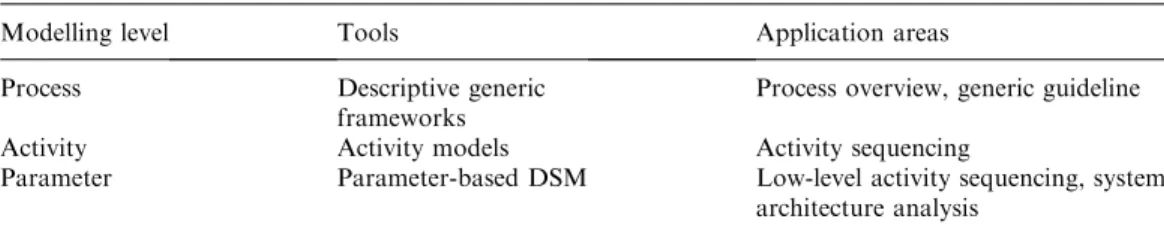
Table 1shows a three-level scheme for process modelling in building
de-sign; parameter-based DSM is presented as the lowest-level process modelling method.
2
A brief review on DSM
The design structure matrix (also known as dependency structure ma-trix) method has its roots in the 1960s, when several efforts were devoted to solving systems of equations.Donald Steward (1981)first coined the term ‘design structure matrix’ and applied these concepts to design. The method gained more credibility as a result of several researches at the Massachusetts Institute of Technology in 1990s.
A design structure matrix is a matrix representation of a system or a project. System components are listed in the first row and the first column of the matrix. Off-diagonal cells indicate the interactions (i.e. dependency, infor-mation flow) between system elements. There are two main categories of DSM; namely, static and time-based (Figure 1). Static DSMs represent ex-isting system elements simultaneously, such as components of a product ar-chitecture or groups in an organization. In time-based DSMs, the ordering of the rows and columns indicates a flow through time; upstream elements of a process precede downstream elements, and terms like ‘feedforward’ and ‘feedback’ become meaningful when referring to interfaces.
There are three dependency configurations that characterize a system in time-based DSMs (Figure 2). Between parallel (independent) activities no information exchange is required. These activities can be executed
Table 1 A three-level scheme for building design process modelling
Modelling level Tools Application areas
Process Descriptive generic frameworks
Process overview, generic guideline
Activity Activity models Activity sequencing
Parameter Parameter-based DSM Low-level activity sequencing, system architecture analysis
simultaneously. Sequential (dependent) activities require sequential infor-mation transfer and they are typically performed in series. Coupled (inter-dependent) activities are mutually dependent on information and they often require multiple iterations to complete. The DSM method facilitates for minimizing iterations in the process. Partitioning and tearing are two operations used for this purpose. Partitioning is the process of re-ordering the DSM rows and columns so that the new arrangement does not contain iterations (i.e. the DSM is transformed into lower triangular form). For complex systems, it is often impossible to obtain a lower trian-gular form DSM by partitioning. In this case, the aim is to move the feed-back marks as close as possible to the diagonal so that fewer system elements are involved in the iteration cycle (this results in a faster develop-ment process). Tearing is the process of choosing the set of feedback marks that if removed from the matrix will render the matrix lower triangular. The marks that are removed from the matrix are called ‘tears.’ Identifying the tears that result in a lower triangular matrix means that the set of as-sumptions that need to be made in order to start design process iterations.
Activity-based DSM is probably the most exploited DSM type among the others. It has been previously applied in automotive (Krishnan,
Design Structure Matrices
Static Time-based Component-based DSM Team-based DSM Activity-based DSM Parameter-based DSM Figure 1 DSM taxonomy
(adapted fromBrowning,
2001)
Figure 2 Three configurations that characterize a system in D S M a n a l y s i s ( a d a p t e d
1993), aerospace (Rogers and Salas, 1999; English et al., 2001) and manufacturing industries (Eppinger et al., 1994; Tang et al., 2000). The technique has been used in the construction industry by VTT in Fin-land (Huovila and Seren, 1998) and Loughborough University (Austin
et al., 1999). The research team at Loughborough University has
devel-oped a DSM-based design planning technique called Analytical Design Planning Technique (ADePT), the effectiveness of which has been shown in previous research. ADePT has been influential on design pro-cess modelling field and it was integrated into more comprehensive plan-ning systems (Choo et al., 2004; Austin et al., 2002).
3
The parameter-based DSM method
The proposed parameter-based model of design process is based on an understanding of the design process as a series of decisions on parameter values. Oxford English Dictionary (Hornby et al. (ed.), 1995)defines the word ‘parameter’ as ‘something that decides or limits the way in which something can be done.’ This definition implies that parameters should be conceived in a network of dependency relationships. In Computer Aided Design (CAD) literature the term ‘parameter’ is often used as a synonym to ‘attribute’ which stands for a quality or a feature. These definitions are fairly broad to be of use in analytical work. This paper, on the other hand, takes a more focused approach and defines a param-eter as a physical property whose value dparam-etermines a characteristic or be-haviour of a system component.
Being close both to product and process architectures, parameters are the core concepts of designing; thus, they are increasingly becoming a fo-cus of attention in CAD tools. Earlier geometry-based models have been augmented by parametric models (Rotheroe, 2002; Rundell, 2002). In the process modelling field, their importance is also being increasingly recognized.Rouibah and Caskey (2003)identify an emerging ‘parame-ter-based concurrent engineering’ paradigm in engineering design where parameter decisions are considered as the basis of the process. de la
Garza and Alcantara (1997) used parameter dependency network to
represent design rationale in civil engineering.Clarkson and Hamilton
(2000)proposed a parameter-based model of design process called
‘sign-posting’ and they demonstrated the application of the model in the de-sign of helicopter rotor blades.
A parameter-based DSM is a square matrix, which defines the depen-dencies of parameter decisions. The tool is similar to activity-based DSM, but it is used for low-level process sequencing. Thus, the level of analysis constitutes a main difference between activity- and
parameter-based DSMs. These two types of DSMs also differ in the scope of their representations. While an activity-based DSM includes re-views, tests, and analyses, a parameter-based DSM documents the phys-ical and rational relationships between the parameters that determine design. In other words, a parameter-based DSM describes design pro-cesses close to the product architecture (Pektasx, 2003a).
The application of the tool is best described by a simple example. The re-lationships between seven parameters affecting plenum depth decision for a suspended ceiling design are shown in an initial parameter-based DSM
inFigure 3(a). The existence of a dependency is shown by an X. Reading
across a row shows input resources; reading down a column shows output sinks. For example, the marks in row E denote that parameter E requires information from parameters C and D. If the parameter decisions were made in the order of A through G, it would be desirable for all informa-tion required by each parameter to have been already generated by a pre-decessor parameter decision. It can be seen inFigure 3(a) that this is not the case for some of the parameters. Parameter B, for example, requires information from parameters A and G. However, information from the parameter G has not been made available. Thus, the decision about the value of parameter G needs to be made before that for B. If the sequence of parameters was changed so as to have a lower triangular matrix, with all the marks below the diagonal, an optimum sequence for parameter de-cisions could be realized. This re-ordering is achieved by using some par-titioning algorithms; the resulting matrix is shown inFigure 3(b). As can be seen in the figure, however, there is a further problem: a two-way de-pendency loop or coupling exists between parameters C and E. Complex processes like building design include many such problems and DSM is very useful for identifying them. The following section demonstrates how the DSM method can be applied in real-life design tasks.
4
A case study on suspended ceiling design process
Two case studies were undertaken to utilize parameter-based DSM in real-life building design problems. The first case study is based on ananalysis of suspended ceiling design process for a public building in Tur-key. The DSM analysis for this case aims to capture the information flows in a specific design configuration. The second case study, which analyzes elevator design, however, aims to produce a generic model of elevator design process. Both of these approaches have been validated in previous DSM researches (Browning, 1998). Within the scope of this paper, only the suspended ceiling design case study is discussed. An extensive discussion of both studies is presented elsewhere (Pektasx,
2003b).
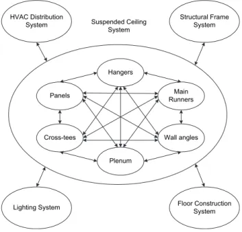
Suspended ceiling design is one of the tasks of a whole building design process in which several subsystems interact with each other. This study analysed suspended ceiling design using a system view of suspended ceil-ing (Figure 4). According to this view, the basic components of a sus-pended ceiling system are panels, main runners and cross-tees, plenum, hangers, and wall angles. The collection of these members con-stitutes the suspended ceiling assembly. Assembly-level DSM of sus-pended ceiling design consists of relations between assembly parameters. Suspended ceiling assembly interacts with four other build-ing systems; namely, Heatbuild-ing, Ventilatbuild-ing and Air-Conditionbuild-ing (HVAC) distribution system, the structural frame system, the lighting system and the floor construction system. The integration of structural members, lighting fixtures, diffusers, and air ducts in plenum constitutes the major problem in design. The situation is complicated further by the
Hangers
Panels
Cross-tees Wall angles
Main Runners Plenum Structural Frame System HVAC Distribution System Floor Construction System Lighting System Suspended Ceiling System
Figure 4 A system design view of suspended ceiling
fact that the elements involved lie in the domains of different building professionals; structural members being designed by structural engi-neers, diffusers and air ducts by mechanical engiengi-neers, and lighting fixtures by electrical engineers. Therefore, the effective (timely, cost-efficient and quality) design of a suspended ceiling necessitates intensive coordination of these participants. The system-level DSM of suspended ceiling design consists of relations between assembly parameters and pa-rameters belonging to the four other interacting systems.
4
.1 Research setting
The research was carried out in the architectural design department of TEPE Construction Company, one of the biggest construction compa-nies in Turkey, and in the offices of their engineering collaborators. The engineering collaborators are privately owned firms led by a chief engi-neer. Design staff employed at these offices includes approximately 4e5 people in each office. Thus, the collaboration between TEPE and its en-gineering collaborators is an example of a distributed collaboration of small design teams, which constitutes the most widespread model in the Turkish AEC industry. The chief architect of the architectural design department of TEPE, and three engineering collaborators (one structural engineer, one mechanical engineer, and one electrical engineer) provided inputs for this research.
4
.2 Objectives of the analysis
The objectives of the analyses are listed below.
1. Identify and document important relations specific to suspended ceil-ing assembly and its interfaces includceil-ing structural frame system, floor system, HVAC system, and lighting system.
2. Study information flow and coupling in suspended ceiling design. 3. Identify critical parameters that cause large iteration cycles. 4. Identify assumptions made in the process.
5. Show knowledge ownership.
6. Define performance requirements for suspended ceiling design and demonstrate how requirements drive design.
7. Compare assembly-level DSM with system-level DSM in terms of dependency intensity, amount and scope of iterative loops and per-centage of information flow contents regarding performance requirements.
4
.3 Collection of the data
DSM analysis of processes requires collection of the data through in-spection of design documents and interviews with designers. This is
often an iterative and time-consuming process. Deeper understanding of the system usually results in modification of the parameter relationships. However, once an initial model is produced, it constitutes the base for further development.
Data for DSM analysis can be collected by participating in design sessions or by interviews after the completion of design process. Both of these ap-proaches have been validated in DSM literature (Browning, 1998). In our study, the latter approach was taken and the data were collected through iterative cycles of detailed interviews which were recorded by a sound recorder. Besides the interviews, the brief, the drawings, and the manufacturers’ information were examined in the study. The initial set of system elements was identified after the initial interviews and they were validated by the experts. The system elements contained not only the physical components in the system, but also performance require-ments. The reason for including the performance requirements in the DSM was to see their relationships with design parameters, and to com-pare assembly- and system-level design from this point of view. All the information flows with the performance requirements satisfied were cap-tured in a database. InFigure 5, ‘Content of Information Flow’ column shows the reason of information exchange in terms of performance re-quirements, i.e. shows performance requirements that are satisfied by a specific flow of information between two parameters.
During the data collection process it was observed that even experienced design professionals such as the architect and the engineers interviewed, had not systematically thought about all aspects of the design. The par-ticipants responded to the interviews very positively, because these inter-views made them think from a systems point of view. In previous DSM examples from product and machinery design field, the researchers had benefited significantly from the documentation of the participating
design organizations (Cesiel, 1993; Dong, 1999; Mascoli, 1999). In our study, however, such documentation was very limited, if it existed at all. This probably points to a difficulty in the building design industry in terms of documenting and guiding processes.
4
.4 Production of the matrices
Using an algorithm (Pektasx, 2003b:p 218) the first draft of the DSMs was produced automatically according to the previously produced database. In the second phase of the data collection process, the draft of the DSMs was shown to the participants and their comments were received. The models were finalized according to the feedbacks from the designers.
4
.5 Analyses and results
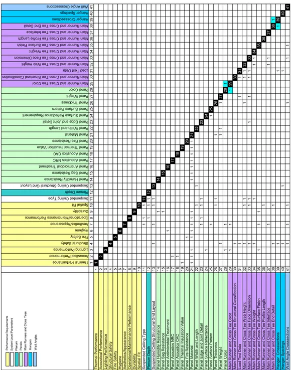
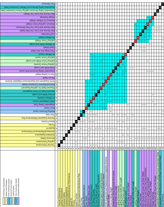
A partitioning algorithm (Pektasx, 2003b:p 223) was used to provide an optimum sequence of parameter decisions and to identify couplings in the process. The partitioning process was purely based on the defined in-terrelationships between the parameters as is common for parameter-based DSM analyses. The resulting matrices are shown in Figures 6
and 7. The assembly-level DSM and the system-level DSM were
com-pared in terms of dependency intensity, total number of elements in loops and percentage of information flow content.
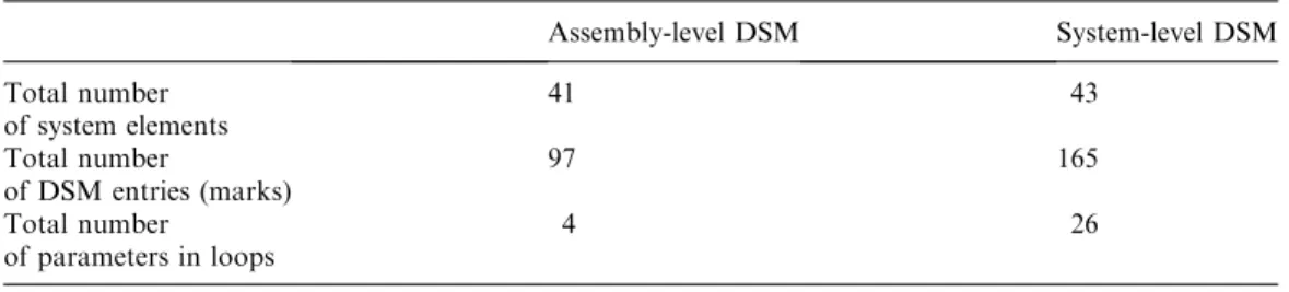
The suspended ceiling system interface DSM contains 165 entries (inter-action points, or DSM marks all of which refer to the information flows), while the assembly DSM contains only 97. The number of system elements are similar in both (approximately 40). Therefore, the sus-pended ceiling system interface is a more complicated problem than the suspended ceiling assembly design. While the system-level DSM con-tains large iteration loops, the assembly-level DSM includes only two very small loops. Sixty percent of the elements of the system-level DSM are in one or more loops; but only 11% for the assembly-level DSM (Table 2). A tearing analysis was performed for the system-level DSM and it was observed that the loops could not be reduced further.
The partitioned DSM of suspended ceiling assembly indicates that pa-rameter decisions at assembly level are made either in a parallel or se-quential manner, but at the system level there are couplings. Previous research showed that the time required for humans to solve a coupled parameter design problem rises geometrically as coupling size rises lin-early (Hirschi and Frey, 2002). This suggests that although suspended ceiling design is simple, it may take more time than planned due to the iterations at the system level.
Thermal Pe rfo rm an ce Acous tic al P erf ormanc e Lighting Perf orma nce Struc tur al Sa fe ty Fire Safe ty Hy giene Aesthe tic s/A ppearanc e Operational/Main tenance P erf orma nce Du ra bility Spat ial Fit Suspended Ceiling Ty pe Plenum Dept h Suspended Ceili ng S tru ctural G rid Layout Pa ne l H um id ity R esist an ce Pan el S ag Resistanc e Panel A nti microbial T reat ment Panel A cous tic s NR C Panel A cous tic s CAC Pa ne l Thermal In su la tio n V alue Pa ne l F ire Resistance Panel Mat erial Panel W idt h and Lengt h Pa ne l E dg e a nd Joint De tail Panel S urf ace Reflec ta nce R eq uir ement Panel S urf ace Pa tter n Panel T hic kn ess Panel W eight Panel Colo r
Main Runner and Cross Tee Colo r Ma in Ru nn er a nd Cross Tee Struct ura l C lassifica tion Load Te st Dat a Main Runner and Cross T ee W eb Height
Main Runner and Cross Tee Fac e Dim ension
Main Runner and Cross Tee We ig ht
Main Runner and Cros s Tee Surface F inish
Main Runner and Cros s Tee Profile Length
Main Runner and Cross T ee In terface
Main Runner and Cross Tee End Detail Hang er Cr os ss ec tio ns Han ge r S pa cin gs Wa ll A ngle Cros ss ections 1 2 3 4 5 6 7 8 9 1 01 1 1 21 31 4 1 51 61 7 1 81 92 0 2 12 22 3 2 42 52 6 2 72 82 9 3 03 13 2 3 33 43 5 3 63 73 8 3 94 04 1 Therm a l Perform a nce 1 1 Aco u s ti c a l Perfo rm a n c e 2 2 Lig h ti n g P e rform a n c e 3 3 S tr u ctu ra l Saf e ty 4 4 Fire S a fe ty 5 5 Hygiene 6 6 Aes th e ti cs/Appearance 7 7 Operati onal /M a in te n ance P e rform a n c e 8 8 Durabi lit y 9 9 S p a ti a l Fit 10 10 S u s p e n d e d C e iling Typ e 11 1 1 1 11 Plenum Depth 12 1 1 1 12 S u s p e n d e d C e iling S tr u ctu ra l Gri d L a y o u t 13 1 1 1 1 13 Panel Humi d it y Resi s ta nce 14 1 14 Panel S a g Resi s tance 15 1 15 P a nel A n ti m icrobial T re a tm e nt 16 1 16 Panel A c o u s ti c s NRC 17 1 17 Pa n e l Acous ti c s C A C 18 1 18 P a n e l T h e rm a l I n s u lat io n V a lu e 19 1 19 Panel F ire Resi s ta nce 20 1 20 Panel M a te rial 2 1 111 1 1 1 11 11 111 1 1 21 P a nel W id th and L e ngt h 22 1 1 22 Pan e l Edge a n d Joi n t D e tai l 2 3 11 11 23 Panel S u rf a c e Ref lectance 24 1 24 P a n e l Surface Patte rn 25 1 1 25 P a nel T h ic kness 26 1 1 1 26 Pa n e l W e ig h t 27 1 1 1 1 27 Panel Col o r 28 1 1 28 1 Mai n Runner a n d Cro s s T e e Col o r 29 1 1 1 29 Mai n Runner a n d Cro s s Tee S tr u c tura l Class if ic a ti o n 30 1 30 Load T e s t Dat a 31 1 11 31 Mai n Runner a n d Cro s s Tee W e b Height 32 1 1 1 1 1 1 32 Mai n Runner a n d Cro s s T e e F a c e Dim e nsi o n 33 1 1 1 1 1 1 1 33 Mai n Runner a nd Cro s s T e e W e ig ht 34 1 1 11 34 Mai n Runner a n d Cro s s T e e Surf a ce F inish 35 1 1 1 35 Mai n Runner a n d Cro s s T e e Profi le Length 36 1 36 Mai n Runner a nd Cro s s Tee In te rf ace 37 1 11 37 Mai n Runner a n d Cro s s
Tee End Det
a il 38 1 1 38 1 Hanger Cro s s s ect ions 39 1 11 39 Hanger S p aci n g s 40 1 1 1 40 W a ll A n gle Crosssect ions 4 1 111 1 1 1 41 P e rf o rm a n c e R e q u ir eme n ts Sys te m L e v e l Par a m e ter s Ple n u m Panels Ma in Runne rs a n d Cro s s T e e s Hange rs Wal l A n g le s
Thermal Perform an ce Ligh tin g P erf ormanc e Stru ctura l S afety Ae sthe tics /App eara nc e Op erat ional /M ain te nanc e P erf ormanc e Spatia l F it Privac y Space Functio n Se rv ices Eq uip me nt M ain te na nce Re q. Floor Area Building Stru ctu re La yo ut Beam Depth Su sp ended Ceiling T ype HVAC Distri bu tion L ayo ut Air Diffu se r Q ua nti ty Air Du ct W idt h a nd Le ngth Requir ed D ept h fo r HVA C Equipment Requir ed De pth fo r Lig hti ng Eq uipm en t Stru ctu ra l Element C on ne cti on D eta ils HV AC Equipment a nd Supers tru ctu re In te gra tion Scheme Plenum Depth Floor to Ceilin g H eig ht Su sp ended Ceiling S tru ctu ral G rid Layo ut Pa ne l W idt h an d Le ngth Lig hti ng Fix tu re Q ua ntity Light in g Fixt ure Widt h an d Lengt h Light in g Fixt ure Layo ut Air Dif fu se r La yout Pa ne l Ed ge a nd Jo in t D eta il Panel We igh t Air Dif fu se r W idt h and Len gth Ligh ting F ixt ure We ig ht Air Diffu se r W eig ht Load T est Dat a Ma in Run ner and Cr oss T ee W eb Height Ma in Run ner an d Cros s Te e F ace Dimens io n Maxim um Lig hti ng F ixt ure We ig ht Ma xim um Air D iffu ser Wei gh t Hange r Spacings Ma in Run ner and Cr oss T ee W eigh t Su sp ended Ceiling S tru ctu re-Light ing F ix tur e Co nnec tion D eta i Sus pen ded Ceiling Str uct ure-Air Di ffu se r Con necti on De ta il Floor Structure 1 2 3 4 5 6 7 9 8 1 01 1 1 21 41 5 1 61 71 8 1 92 02 12 22 3 2 42 52 8 2 93 03 2 2 62 73 3 3 13 43 53 63 7 3 83 94 3 4 04 14 2 1 3 T h er m a l P e rf or m a nc e 1 1 Lighting Pe rf o rm a n c e 2 2 Stru ctu ra l Sa fe ty 3 3 A e s th e ti cs /A pp ear an c e 4 4 O p e ra ti o n a l/ M a in te na nce Pe rf orm a nc e 5 5 S p a tia l Fi t 6 6 Pri v a c y 7 7 S p a c e F u n c ti o n 911 111 9 Se rv ic e s E q u ip m en t M a in te na nce R e q. 8 1 1 8 F loor A rea 10 1 1 10 1 B u il d ing St ru ct u re L a y out 11 1 1 1 11 Be a m D e p th 1 2 1 1 12 11 S u s p end ed Cei li n g T y pe 14 1 1 1 1 1 1 14 1 HVAC D is tri b u tion La yo u t 1 5 1 1 1 1 1 15 11 1 1 Air Di ff u s e r Qua n ti ty 1 6 1 1 1 16 1 A ir D u c t W idt h and Le ngt h 17 1 1 1 1 17 R equ ir ed Dep th f o r HV AC E q u ip m en t 1 8 1 1 1 18 R e qu ir ed Dep th f o r Li g h ti ng Equi p m e n t 19 1 19 1 S tr u c tur a l E lem en t Con n e c ti on Det a il s 2 0 1 1 20 1 H V A C E q u ipm ent and Supers tr u c tu re I n te gr at io n S c he m e 21 1 1 1 1 1 1 21 1 Plen um D e p th 2 2 1 1 1 1 1 1 1 22 Fl o o r t o C e ili n g H e ig h t 2 3 1 1 1 1 1 1 1 1 1 23 S u s p end e d Cei li n g S tr u c tur al G ri d Lay o u t 24 1 1 1 1 24 P a ne l W idt h an d L e ng th 2 5 1 1 25 Li gh ting F ix ture Q u a n ti ty 2 8 1 1 1 1 28 L ig h ti n g F ix tu re W idt h and Le ngt h 29 1 1 29 Li gh ting F ix ture L a y o u t 3 0 1 1 1 1 1 1 1 30 1 Air Di ff u s e r La yo ut 3 2 1 1 1 1 32 P a n e l Edge a n d J o in t Det a il 26 1 1 1 1 26 P a n e l W e ig h t 2 7 1 1 27 Air Di ff u s e r W idth an d Le n g th 3 3 1 1 1 33 Li gh ting F ix ture W e ig ht 3 1 1 31 1 Air Di ff u s e r W e ig h t 3 4 1 34 1 Lo ad T e s t Da ta 3 5 1 11 1 35 M a in Ru nn er an d Cr os s T e e W e b H e ig ht 36 1 1 1 1 1 1 1 1 36 M a in Ru nn er an d Cr os s T e e F a c e D im e ns io n 3 7 1 1 1 1 1 1 1 1 37 M a x im u m Li g h ting F ix ture W e ig ht 3 8 1 11 1 1 38 1 M a x im u m A ir D if fus er W e ig ht 39 1 11 1 1 39 1 H a ng er S p ac in gs 43 1 1 1 1 1 43 M a in Ru nn er an d Cr os s T e e W e ig ht 40 1 1 11 40 S u s p end ed Cei li n g S tr u c tur e-L igh ti n g F ix tu re Con n e c ti on Det a il 41 1 1 11 41 S u s p end ed Cei li n g S tr u c tur e-A ir Di ff us er C onn ec ti o n De ta il 42 1 1 11 42 F lo o r Stru ctu re 1 3 1 1 1 11 1 1 13 P e rf or m a n c e R e q u ir emen ts Sy st e m L e ve l Pa ra m e te rs H V A C D is tr ibut io n S y s te m S tr u c tu ral F ram e S y s tem Light ing Sy s te m F lo o r C o ns tr u c ti o n S ys te m Su s p e n d e d C e iling Sy s te m
Decisions on some parameters affect a large number of parameters in building design. Consequently, the changes in those ‘critical’ parameters are more likely to cause larger iteration cycles. Fifteen critical parame-ters (such as plenum depth, lighting fixture quantity and weight, etc.) were defined for suspended ceiling design at system level; however, there were no critical parameters at the assembly-level design. Critical param-eters were identified by manual manipulation and observation of the matrices. Although this technique produced satisfactory results for our study, there is a more systematic approach to identify critical pa-rameters based on coupling strengths (Chen et al., 2003) which can be used in further research. The schedule of the assumptions made in the process was also identified. For example, it is observed that correct as-sumptions about floor to ceiling height, air diffuser quantity and the in-tegration scheme of HVAC and superstructure at the beginning of the process are likely to prevent costly changes in the HVAC distribution layout.
The percentage contents of information flows were calculated for both assembly and system-level DSMs according to the data illustrated in
Figure 5. The results are shown inFigure 8.
5
Implications on the design process drawn from
the case study
Besides the insights gained into the individual design processes, some common implications can be drawn from the case study.
The first observation about the design processes concerns the types of information flows. There are at least four types of knowledge used in de-termining the parameter values:
1. There exist a number of formulas, through which existing design val-ues are used to compute a new parameter value. These formulas are often based on physical laws. For example, the sum of maximum
Table 2 A comparison between the assembly- and the system-level DSMs
Assembly-level DSM System-level DSM Total number of system elements 41 43 Total number of DSM entries (marks) 97 165 Total number of parameters in loops 4 26
weights of air diffusers and lighting fixtures that can be carried by the suspended ceiling structure is equal to the load test data of the system.
2. Some parameters create constraints for other parameters. In other words, they bring about limitations on the choices for other param-eters. For example, in suspended ceiling design, beam depth puts lim-itations on the minimum plenum depth.
3. Design professionals use preferences to decide on a parameter value when no other parameter dictates a choice. These preferences can be measured with an ordinal scale. Preferences with a higher value are considered as being more important (e.g. lowest cost). This is often the case when decisions are made on finishes. Parameters related to finishes are mostly not dependent on other parameters (although they depend on each other to ensure compatibility in design), but based on client’s and/or designer’s preferences.
4. When a design problem occurs, for example, when a violation of a con-straint indicates that a rework is needed, the designers use fixes to modify the design. Each fix affects specific parameters that are depen-dent on the changed parameter. Parameter-based DSM is very useful to track the parameters affected by such changes.
In the case study, it was also observed that certain aspects of design are more prone to iterations. First of all, it was observed that early design stage includes more iterative cycles. The problematic situation of early design (also called conceptual design) is well addressed in the literature.
0 5 10 15 20 25 30 35 40 45 Acoustics Appearance Durability Fire Safety Hygiene Lighting Maintenance Privacy Spatial Fit Structural Safety Thermal Assembly Level System Level
Figure 8 Information flow percentages in the system-and the assembly-level DSMs
In building design, most of the important decisions (orientation, circu-lation, functional layout, etc.) are made in the early stages of design. However, most design software cannot support this stage of design de-velopment (Tasxlı and O¨zgu¨c¸, 2001).
Decisions made in the early steps of design often have far-reaching and unanticipated impacts at later stages. However, it is often too costly to modify such decisions as the design advances since they affect many pa-rameters and are likely to create ‘iterations in iterations.’ In order to re-solve this dilemma, the assumptions related to early design parameters should be accurate and/or parameter values should be determined with tolerances to compensate for future changes. Making accurate as-sumptions or deciding on acceptable range of parameter values correctly require to get the right information to the right person at the right time and the DSM method is very useful for this purpose.
Furthermore, it was observed that the most critical parameters, from de-sign management perspective, are those that affect many parameters. These include:
1. System parameters, which affect either all or most of the parameters (e.g. floor area, floor height, etc.).
2. Interface parameters, which specify a relation between two system components engineered by different design professionals (fitting di-mensions, forces to be transmitted, etc.).
A major challenge of the proposed parameter-based DSM approach is the large number of parameters involved in building design. The number of parameters needed to fully determine the properties of a product de-pends on its complexity.Rouibah and Caskey (2003)estimate that an automobile can be described by 105e106parameters, while an aircraft or ship may have more than 106. There is no available estimation of
ap-proximately how many parameters a building may involve, but a fairly large number is to be expected. Consequently, to capture and manage all describing parameters in building design may be unrealistic. Therefore, a selection should be made depending on the purpose of the parameter deployment. If the number of considered parameters is based on the crit-ical parameters mentioned above, the number of parameters to be cap-tured reduces considerably.
Finally, the DSM analyses revealed that the technical aspects of design-ing a builddesign-ing part are usually well understood and relatively easy to manage. Suspended ceiling design at assembly level is an example of
this type of design which is also called ‘standard design’ or ‘kit-of-the-parts’ design. However, problems often occur when parts are integrated into a system, and have to interact with other elements in the system. Suspended ceiling design at system level is an example for this phenom-enon. This latter type of design is difficult to manage and often not suit-able for automation. In most of the cases, human intervention is essential to deal with the conflicts in system-level design. The DSM method is especially useful for modelling complex system designs be-cause of its analytical and concise representation scheme.
6
Conclusions
The AEC industry, like many others, is increasingly aware of the need to improve efficiency of processes in a competitive marketplace. However, the industry has experienced difficulties in identifying ways of capturing, understanding, and replicating design processes. Guided by the observa-tions above, this paper has proposed parameter-based DSM as a system analysis and process modelling tool for building design. In a case study, it is shown that parameter-based DSMs provide a structural map of the design processes. They identify iterative cycles, critical parameters, and as-sumptions that need to be made. They also suggest proper sequence of de-sign decisions and provide insights into the concurrency in the processes. Although the method has a prescriptive value, unlike many other process modelling methods used in the industry, DSM analysis does not dictate a single ‘right’ process. Instead, it pictures the structure of the dependency relations in the process so that designers may produce several ‘what-if’ sce-narios to determine the effects of change. An illustrative case for the ‘what-if’ scenarios was presented in a paper byBaldwin et al. (1998).
DSM models represent extensive system knowledge. Thus, they are very work intensive and they can be difficult to build initially. In practice, DSM-based approaches may have to overcome barriers such as lack of source documentation, ignorance or lack of system thinking. However, our experience with design professionals suggested that with a short time of learning and application, experts developed an understanding of DSM and responded positively to it. Although it is very knowledge in-tensive, the DSM method enabled the representation of the processes studied in the case studies in a compact form. If the same processes were modelled with a graphical technique, the models would probably occupy numerous sheets. Thus, their management and integration would be a considerable problem.
The case study also revealed that, in most cases, the design knowledge needed to resolve design issues resides in more than one design
professional. The database developed in the study showed what infor-mation needs to be exchanged as well as dependencies between the deci-sions. A database as such can serve to accumulate the learning in design firms, providing a complement to the existing inefficient documentation practice. It can serve as a browser for designers to find out what decision they need to make and with whom they need to communicate. A parameter-based DSM can be effectively used as a tool to control the change propagation. In an on-going design process, when a parameter value is changed, it is very easy to extract the affected parameters using the dependency network. During collaborative design, as different de-sign participants decide on parameter values, capturing the relationship between parameters consequently specifies the relationship between the decision-makers. Who should be informed about a change and the se-quence of actions that should be taken can also be easily determined us-ing the tool. Similarly, when the design is finished the model may be used in monitoring changes in the design process to avoid oversight.
Ter-wiesch and Loch (1999) demonstrated such a use of the model in the
case of a climate control system in automobile development.
The use of parameter-based DSM in building design may trigger further researches in many directions. For example, this paper utilized only bi-nary parameter-based DSMs. Further research may be done to enhance the existing models by assigning numerical values to the dependencies to qualify the importance and strength of the dependency. A multitude of other attributes that provide more detailed information on the relation-ships can also be provided. The probability of repetition, the variability of information exchanged, and the impact of an iteration can also be in-cluded in the analysis in order to simulate the modelled processes. Parameter-based DSM facilitates comparison of different design config-urations. A DSM can be produced for each design option and different designs may be compared in terms of their complexity and how a change in design affects the overall process structure. In this case, the amount of system elements and information flows would be a good indicator of de-sign complexity. When dede-sign configurations are compared, their prob-lematic aspects can be identified and new designs can be modified in the light of the gained insights.
Finally, parameter-based DSMs are truly integrative applications and a combinational use of top-down and bottom-up techniques in process modelling may reveal valuable insights into the process structure. A dis-cussion on how the parameter-based DSM can be used to integrate an
activity-level AEC process model is presented elsewhere (Pektasx, 2003c). We are currently working to exploit this capability of the method and to develop it as a tool available for using in any building design project.
Acknowledgements
The authors would like to thank TEPE Construction Company and the design professionals who have contributed to the case study.
References
Arditi, D and Gu¨naydın, H M (1998) Factors that affect process quality in the life cycle of building projects Journal of Construction Engineering and ManagementVol 124 No 3 pp 194e203
Austin, S, Baldwin, A, Li, B and Waskett, P (1999) Analytical design plan-ning technique: a model of the detailed design process Design Studies Vol 20 No 3 pp 279e296
Austin, S, Newton, A, Steele, J and Waskett, P (2002) Modeling and man-aging project complexity International Journal of Project Management Vol 20 pp 191e198
Baldwin, A N, Austin, S, Hassan, T M and Thorpe, A (1999) Modelling information flow during the conceptual and schematic stages of building design Construction Management and Economics Vol 17 pp 155e167 Baldwin, A N, Austin, S, Hassan, T M and Thorpe, A (1998) Planning build-ing design by simulatbuild-ing information flow Automation in Construction Vol 8 pp 149e163
Black, T A, Fine, C F and Sachs, E M A (1990) Method for systems design using precedence relationships: an application to automotive break sys-tems, Working Paper, MIT School of Management, Cambridge, MA, USA Browning, T R (1998) Modeling and analyzing cost, schedule, and perfor-mance in complex system product development, Ph.D. Dissertation, Tech-nology, Management, and Policy Program, Massachusetts Institute of Technology
Browning, T R (2001) Applying the design structure matrix to system de-composition and integration problems: a review and new directions IEEE Transactions on Engineering ManagementVol 48 No 3 pp 292e306 Cesiel, D S (1993) A structured approach to calibration development for automotive diagnostic systems, M.Sc. Dissertation, Department of Electri-cal Engineering, Massachusetts Institute of Technology
Chen, C, Ling, S F and Chen, W (2003) Project scheduling for collaborative product development using DSM International Journal of Project Manage-mentVol 21 pp 291e299
Choo, H J, Hammond, J, Tommelein, I D, Austin, S M and Ballard, G (2004) DePlan: a tool for integrated design management Automation in ConstructionVol 13 pp 313e326
Clarkson, P J and Hamilton, J R (2000) ‘‘Signposting’’, a parameter-driven task-based model of the design process Research in Engineering Design Vol 12 pp 18e38
Cornick, T (1991) Quality management for building design Butterworth-Heinemann, London, UK
Cross, N A (1989) Engineering design methods John Wiley and Sons, Chi-chester, UK
de la Garza, J and Alcantara, P (1997) Using parameter dependency net-work to represent design rationale Journal of Computing in Civil Engineer-ingVol 11 No 2 pp 102e112
Dong, Q (1999) Representing information flow and knowledge management in design using the design structure matrix, M.Sc. Dissertation, Department of Mechanical Engineering, Massachusetts Institute of Technology English, K, Bloebaum, C L and Miller, E (2001) Development of multiple cycle coupling suspension in the optimization of complex systems Structural and Multidisciplinary OptimizationVol 22 No 4 pp 268e283
Eppinger, S D, Whitney, D E, Smith, R P and Gebala, D A (1994) A model-based method for organizing tasks in product development Research in Engineering DesignVol 6 pp 1e13
Formoso, C T , Tzotzopoulos, P, Jobim, M S S and Liedtke, R (1998) Devel-oping a protocol for managing the design process in the building industry, International Group for Lean Construction, Sixth Annual Conference, Retrieved May 2002 from: http://www.ce.berkeley.edu/wtommelein/ IGLC-6/FormosoTzotzopoulosJobimLeidtke.pdf
Hirschi, N W and Frey, D D (2002) Cognition and complexity: an experi-ment on the effect of coupling in parameter design Research in Engineering DesignVol 13 pp 123e131
Hong, N K and Hong, S (2001) Application of entity-based approach for unified representation of design alternatives for structural design Advances in Engineering SoftwareVol 32 pp 599e610
Hornby A S, Kavanagh K and Ashby M (eds) (1995) Oxford advanced learn-er’s english dictionary5thedn, Oxford University Press, UK
Hubka, V (1982) Principles of engineering design Butterworth Scientific Press, Guildford, Surrey, UK
Huovila, P and Seren, K J (1998) Customer-oriented design methods for construction projects Journal of Engineering Design Vol 9 No 3 pp 225e238 Karhu, V (2000) Proposed new method for construction process modelling International Journal of Computer Integrated Design and ConstructionVol 2 No 3 pp 166e182
Krishnan, W (1993) Design process improvement: sequencing and overlap-ping activities in product development, Ph.D. Dissertation, Department of Mechanical Engineering, Massachusetts Institute of Technology
Malmstro¨m, J, Pikosz, P and Malmqvist, J (1999) Complementary roles of IDEF0 and DSM for the modelling of information management processes Concurrent Engineering e Research and Applications Vol 7 No 2 pp 95e103
Mascoli, G J (1999) A systems engineering approach to aero engine devel-opment in a highly distributed engineering and manufacturing environ-ment, MIT SDM Thesis, Massachusetts Institute of Technology
MIT DSM Research Group (2005) MIT DSM Web Site http:// www.dsmweb.org/
Pahl, G and Beitz, W (1984) Engineering design The Design Council, Lon-don, UK
Pektasx, Sx T (2003a) A framework for building design process modeling with parameter-based design structure matrices in C J Anumba (ed)
Innovative developments in architecture, engineering and construction, Mill-press, Rotterdam, The Netherlands pp 63e72
Pektasx, Sx T (2003b) Representing information flow in building design pro-cess using the parameter-based design structure matrix, Ph.D. Dissertation, Bilkent University, Ankara
Pektasx, Sx T (2003c) Process integration in building design using the param-eter-based design structure matrix in B Tunc¸er, S S Ozsariyildiz and S S Sariyildiz (eds) E-Activities in building design and construction, Europia Productions, Paris, France pp 63e72
Phillips, R (2001) The architect’s plan of work RIBA Publications, London, UK
Pugh, S (1986) Design activity models: worldwide emergence and conver-gence Design Studies Vol 7 No 3 pp 167e173
Pultar, M (1990) Progress based construction scheduling Journal of Con-struction Engineering and ManagementVol 116 No 4 pp 670e688 Rezgui, Y, Zarli, A, Bourdeau, M and Cooper, G (2002) Inter-enterprise information management in dynamic virtual environments: the OSMOS approach, Proceedings of the International Council for Research and Innovation in Building and Construction CIB W78 Conference, Retrieved Feb-ruary 15, 2003,from http://cic.cstb.fr/ilc/publicat/rezgui_cibw78.pdf
Rogers, J L and Salas, A O (1999) Toward a more flexible web-based framework for multidisciplinary design Advances in Engineering Software Vol 30 pp 439e444
Rotheroe, K (2002) A vision for parametric design, Architecture Week, Re-trieved December 2002, fromhttp://www.architectureweek.com/2002/0710/ tools_1-1.html
Rouibah, K and Caskey, K R (2003) Change management in concurrent engi-neering from a parameter perspective Computers in Industry Vol 50 pp 15e34 Rounce, G (1998) Quality, waste and cost considerations in architectural building design management International Journal of Project Management Vol 16 No 2 pp 123e127
Rundell, R L (2002) Parametrics in building design, CAD Server: Online Re-source for the CAD Community, Retrieved December 2002, from http:// www.cadserver.co.uk/common/viewer/archive/2002/Apr/9/feature.htm
Sanvido, V E and Norton, K J (1994) Integrated design process model Jour-nal of Management in EngineeringVol 5 pp 55e62
Smith, R P and Eppinger, S D (1999) A predictive model of sequential iter-ation in engineering design Management Science Vol 43 pp 1104e1120 Steward, D V (1981) The design structure system: a method for managing the design of complex systems IEEE Transactions on Engineering Manage-mentVol 28 pp 71e74
Tang, D, Zheng, L, Li, Z, Li, D and Zhang, S (2000) Re-engineering of the design process for concurrent engineering Computers and Industrial Engi-neeringVol 38 pp 479e491
Tasxlı, Sx and O¨zgu¨c¸, B (2001) Dynamic simulation in virtual environments as an evaluation tool for architectural design Architectural Science Review Vol 44 No 2 pp 139e144
Terwiesch, C and Loch, C H (1999) Managing the process of engineering change orders: the case of the climate control system in automobile devel-opment Journal of Product Innovation Management Vol 16 pp 160e172
Tolman, F P (1999) Product modelling standards for the building and con-struction industry: past, present and future Automation in Concon-struction Vol 8 pp 227e235
Wakefield, R R and Damrianant, J (1999) Petri net modelling e a simulation tool for use in construction process re-engineering International Journal of IT in Architecture, Engineering, and ConstructionVol 1 No 2 pp 20e34 Wu, S, Fleming, A, Aouad, G and Cooper, R (1998) The development of the process protocol mapping methodology and the tool, Proceedings of the European Product Data Technology Conference, Building Research Estab-lishment, Watford, UK, Retrieved April 2002, fromhttp://pp2.dct.salford. ac.uk/pdf/pdt98.pdf