1
An Image Watermarking Algorithm via Zero
Assigned Filter Banks
Zeynep Y¨ucel and A. B¨ulent ¨
Ozg¨uler
Electrical and Electronics Engineering Department
Bilkent University, 06800, Bilkent, Ankara, Turkey.
Abstract In this paper a new method for digital image
watermarking based on Zero Assigned Filter Banks and Em-bedded Zero Tree Wavelet (EZW) algorithm is presented. An image is partitioned into 128 × 128 subblocks and each block is processed in a three stage decomposition structure by a filter bank which is assigned a zero around the stop band. The coefficients to be marked are chosen according to the EZW algorithm. This method not only provides a robust watermarking scheme but may also be used as an effective compression strategy. The algorithm is tested under white Gaussian noise and against JPEG compression and it is observed to be robust even when exposed to high levels of corruption.
I. INTRODUCTION
Recent developments in multimedia technology has made digital video, audio, and image watermarking a significant issue. There are several essential conditions that must be met by an effective watermarking algorithm. The signature of the author, the watermark, needs to be not only transparent to the user but also robust against attacks, [10]. These attacks may include degradations resulting from a transmission channel, compression of the signal, rotation, filtering, permutations or quantization. On the other hand, the watermarking procedure should be invertible. The watermark must be recovered from the marked data preferably without access to the original signal. Since watermarking plays an important role in copyright protection, security turns out to be critical. Even if the exact algorithm is available to a pirate, he should not be able to extract or predict the watermark without access to the security keys.
Since human auditory and visual systems are imperfect detectors, the watermark can be made imperceptible via appropriate masking. In visual masking, watermark signal is usually embedded in the detail bands of the signal. This may, however, make the watermark more fragile against attacks like high frequency filtering and such. Imperceptibility should be counterbalanced against robustness. Wavelets and filter banks offer a great deal of advantages in terms of these requirements. The motivation of wavelets is to decompose the input signal into approximation and detail portions which complement each other. A series of these complementary
Zeynep Y¨ucel, (e-mail: [email protected]), A. B¨ulent Ozg¨uler,¨ (email: [email protected]).
decompositions lead us to the wavelet transformation, [15]. One of the early image watermarking methods using wavelets was suggested by Xia et al., [13] (also see [7]), where a white noise with masking was added on top of the detail portions, i.e., HL, LH or HH of the discrete wavelet transform of the image. Since compression schemes degrade the HH band most, LH or HL band is preferred for robustness against compression. The detection scheme of [13] consisted of computing the correlation of the extracted watermark with the original watermark signal so that one needs to store the embedded watermark and transmit it to the receiver side. Embedded zero-tree wavelets (EZW) has also been employed in watermarking applications in selecting the appropriate detail band coefficients for embedding the watermark, [6], [9]. In 1993, Shapiro proposed an efficient low bit rate image coding algorithm based on the self similarity of wavelet coefficients, [3]. He found out that if the coefficients at a coarser scale are insignificant with respect to some amplitude threshold T , then the ones which correspond to the same spatial location at a finer scale are also likely to be insignificant with respect to T . A coefficient at a coarse scale satisfying this self similarity condition is called to be the parent and the coefficients corresponding to the same spatial location at finer scales are called to be its children. Identifying the parents and their children which are insignificant with respect to T , one constructs a zero tree which lets him detect the perceptually inconsequential regions and embeds a signature there. Because of the spread spectrum handling of data offered by the multiresolution property of the filter banks, there is an opportunity to increase the robustness while keeping the degradations as small as possible, [6]. In [9], in order to facilitate the decoding phase of the watermark, rather than erasing the insignificant coefficients, a nonzero number called the embedded intensity replaces these coefficients. In the decoding phase, the mean of the coefficients which are known to be on the zero tree is computed and the correct embedded bit is determined according to the sign of the mean value. In [2], another method based on the idea of EZW is proposed based on “qualified significant coefficients” that are
between two thresholds T1 and T2.
In our previous work, [12], text data was embedded in different types of audio signals, such as male voice, female voice, male voice with pauses, and music signal. Two filter
banks F B0 and F B1 designed by using minimal-length FIR
low-pass analysis filters with assigned zeros at frequencies f0
363 0-7803-9314-7/05/$20.00©2005 IEEE
Symposium on Signal Processing and Information Technology
and f1, respectively, were used to embed a watermark. In this
method, the audio signal is first partitioned into a number of time frames and each frame is wavelet decomposed using
either F B0 or F B1, depending on the bit to be embedded
in that frame, and the 3rd level detail coefficients are set to
zero. The sequence of 1’s and 0’s embedded in consecutive frames allows us to encode text information as the watermark. In the decoding phase, each frame is processed with both filter banks and a suitable norm of the detail coefficients are examined to detect the embedded bit in that frame. Since minimal-length, zero-assigned, perfect reconstruction FIR filter banks are essentially unique, [11], the necessary key information to be stored for the detection of the watermark is minimal.
Here, we adapt the zero-assigned filter bank method of [12] to image watermarking while making the method more robust against attacks via employment of embedded zero-tree wavelets. While keeping the advantages of the earlier image watermarking methods, we reduce the amount of key information needed in the detection phase. The proposed scheme embeds the watermark in the perceptually transparent parts of the image by replacing the amplitude of the zero-tree elements by +m or −m, which leads to a reduction in the amount of transmitted information. When the watermark is regarded as a noise introduced on the image, PSNR (peak signal-to-noise ratio) is a good measure of imperceptibility and it must be as high as possible. On the other hand, successful detection of the watermark under as low a PSNR as possible is a measure of the robustness of the method against distortion type of attacks. We illustrate in detail under white Gaussian noise and compression attacks that the proposed method here improves both PSNR properties in comparison to the earlier methods proposed in [5], [8], and [1].
II. ZERO-ASSIGNEDFILTERBANKS
In a perfect reconstruction (PR) quadrature mirror filter bank, synthesis filters are completely determined by the analy-sis filters, [4], so that the construction of the filter bank reduces to the construction of the analysis filters. The zero assignment in our method refers to the construction of finite impulse response (FIR), quadrature mirror (QM), and minimal length analysis filters having assigned zeros at desired locations with respect to the unit circle (or at desired frequencies), [11]. We now summarize the PR, FIR, QM, and minimal length filter bank construction method of [11]. Suppose a permitted odd
filter bank delay of n0 is given. Further suppose that G1(z)
and G2(z) are two FIR transfer functions of order (number of
zeros) k each whose zeros coincide with the desired zeros of
the analysis low-pass filter H1(z) and high-pass filter H2(z),
respectively. Thus, the analysis filters will contain desired zeros if and only if
H1(z) = ˆH1(z)G1(z)
H2(z) = ˆH2(z)G2(z)
(1) The PR condition derived in [11] is
H1(z)H2(−z) − H1(−z)H2(z) = 2z−n0 (2)
With a further simplification in equation 2 the terms may be replaced with G(z) and H(z) where
G(z) = G1(z)G2(−z)
H(z) = ˆH1(z) ˆH2(−z) (3)
Writing the terms explicitly and arranging them by equation 3
G(z)H(z) − G(−z)H(−z) = 2z−n0 (4)
For this equation to have a solution, it is necessary that the greatest common divisor of (G(z), G(−z)) is of the form
z−m, i.e., it should be a pure delay. In [11] it is shown
that a minimal length FIR solution H(z) exits and is unique
whenever n0< 4k and has order at most 2k−2, where k is the
number of assigned zeros provided that G(z) and G(−z) are coprime. The analysis filters are obtained by a factorization
H(z) = ˆH1(z) ˆH2(−z) (5)
and are in general non-unique. A hand-rule is to select the left half plane zeros in the low-pass filter and right half plane zeros in the high-pass filter, [11]. The values of the k assigned zeros to the low-pass filter uniquely determines the filter bank provided this hand rule is used and it is agreed that each filter in the filter bank has order at most 2k − 2. Note that this is a generalization of a result of Daubechies concerning the PR, QM filter banks that correspond to Daubechies filters, in which the assigned zeros of the low-pass analysis filters are always at −1.
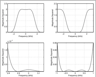
As an example, suppose that the desired zeros to be assigned are at −1, −0.97 + 0.2431i, −0.97 − 0.2431i for the low-pass filter and at 1, 0.8 + 0.6i, 0.8 − 0.6i for the high-pass filter. Suppose that the duration of the allowable delay is
n0= 5. Under these circumstances, a minimal order solution
to equation 1 and its factorization according to the hand rule described above produces the following high-pass and low-pass filters of order four each with frequency responses given in Figure 1.
III. METHODOLOGY
Generally speaking, the method consists of embedding binary data into a gray level image. The image is partitioned into frames, where each frame is assigned one bit, ‘0’ or ‘1’, as illustrated in Figure 3. Two filter banks of the same order but different zeros assigned on their stop bands are constructed to designate a ‘0’ or ‘1’ in each frame. Conceptually, the embedded watermark is as shown in Figure 2, where the diagonal frames correspond to bits ‘0’ and the off-diagonal frames to bits ‘1’.
In order to differentiate between the assigned bits, each frame is processed by one of the filter banks and a multiresolution representation is obtained as in Figure 3. Since, in the filter bank structure, a downsampling operation is involved at each stage, every pixel in the original image corresponds to four pixels at the next finer scale. After the zero trees are constructed on LH or HL bands, the tree elements are
−2 0 2 0 0.5 1 1.5 2 2.5 Frequency (kHz) Magnitude Squared −2 0 2 0 0.5 1 1.5 2 2.5 Frequency (kHz) Magnitude Squared 2.8 2.9 3 3.1 0 0.5 1 1.5 2x 10 −4 Frequency (kHz) Magnitude Squared −1 −0.5 0 0.5 1 0 0.02 0.04 0.06 0.08 Frequency (kHz) Magnitude Squared
Fig. 1. Frequency responses of zero-assigned filters (a) Low-pass filter (b) High-pass filter (c)Zoomed image around the asssigned zero for LPF (d) Zoomed image around assigned zero for HPF
Fig. 2. An Example Watermark
replaced with m or −m depending on the assigned bit. Besides the differentiation introduced by using two different filter banks, this replacement leads to a further distinction in spread spectrum analysis. In the decoding phase the received image is partitioned into frames again and each frame is processed with both of the filter banks. The mean value of the zero tree coefficients of these two decompositions are compared. The value which turns out to be closer to the expected mean of the zero tree elements of the decomposition of a particular filter bank is supposed to be dominant and the bit that filter bank implies is chosen. We now describe the main steps of our method of watermark embedding and extraction.
Watermark Embedding and Extraction
LL1 LH1 HL1 HH1 LL2 LH2 HL2 HH2 LL3 LH3 HL3 HH3 128 128
Fig. 3. General structure of the algorithm Embedding one bit into a frame
Encoding:
Step I
The image is partitioned into subblocks, or frames, S1, ..., SN
of a fixed size. The number N of subblocks correspond to the number of bits to be embedded as a watermark.
Step II
Two different filter banks F B0 and F B1, having assigned
zeros on the stop band are designed using the zero-assignment method described above and the construction algorithm of [11].
Step III
Each frame Si, i = 1, ..., N is wavelet decomposed according
to the “cascade algorithm”, [15], where either F B0 or F B1
is employed depending on whether ‘0’ or ‘1’ is the bit to be embedded. An L-level multiresolution decomposition Di
of each Si is so obtained. (In our case L = 3 as shown in
Figure 3.) Step IV
The insignificant coefficients on LH or HL bands of Di
are determined according to the EZW algorithm for each
i = 1, ..., N . The root location matrices Mi are generated for
each i = 1, ..., N . (In our case, LH band is used.) Step V
The zero-tree elements of Di are replaced with some
fixed number m or −m, depending on whether Di is
obtained using F B0 or F B1. (Since the filter banks are
perfectly reconstructing and the selected coefficients are not perceptually significant, one expects that the marked image will not suffer from any significant degradation.)
Decoding:
Root Pixel in LH3
Descendants in LH2
Descendants in LH1
Fig. 4. Formation of a zero-tree
Only the numbers N , L, m, the matrices Mi, i = 1, ..., N ,
and the values of the assigned zeros in F B0 and F B1 need
be stored or transmitted in order to successfully extract the watermark from the marked image.
Step I
The filter banks F B0or F B1are constructed using values of
the assigned zeros and the construction algorithm of [11]. Step II
A possibly attacked image is partitioned into frames S1, ..., SN
and each frame Si is wavelet decomposed into D0i and D1i
using F B0 and F B1, respectively.
Step III
Using the root locations matrix Mi both for D0i and D1i,
the mean values m0i and m1i of the “previously insignificant
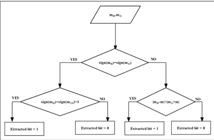
coefficients” are computed. Whether the frame i contains
‘0’ or ‘1’ is resolved according to the decision algorithm of
Figure 5. If both m0i > 0 and m1i > 0, then it is inferred
that the embedded bit is ‘1’. Similarly, if m0i < 0 and
m1i< 0, the extracted bit is 0. If m0i> 0 and m1i < 0, then
both of these mean values are consistent with decompositions
obtained via F B0 and F B1 so that both ‘0’ and ‘1’ are
plausible. In such a case we compare |m0− m| and |m1+ m|.
If |m0− m| < |m1+ m|, then extracted bit is decided to be
‘1’, otherwise ‘0’. Finally, if m0i < 0 and m1i > 0, then
both are inconsistent with decompositions obtained via F B0
or F B1 so that neither ‘0’ nor ‘1’ is plausible. In this case
we again compare |m0− m| and |m1+ m| and decide for
‘0’ if |m0− m| > |m1+ m|, and for ‘1’ otherwise.
From the aspect of storage and security requirements,
m0i,m1i
sign(m0i)=sign(m1i)
sign(m0i)=sign(m11i)=1 |m0i-m|<|m1i+m|
YES NO
Extracted bit = 1 Extracted bit = 0 Extracted bit = 1 Extracted bit = 0
YES NO YES NO
Fig. 5. Decision Algorithm
our method brings many advantages. The angle and the magnitude of each assigned zero are enough to compute the filter coefficients so this not only decreases the amount of transmitted data, i.e., the bandwidth requirement, but also makes the algorithm more secure unless the whole design procedure is available to a pirate. The locations of the insignificant coefficients must be stored in a simple binary matrix against any attack on the watermarked image. Attacks may change the roots, hence resulting in a different tree. However, the computational complexity or storage space does not cost much, since it is enough to keep the root locations to reconstruct the whole tree and since the size of each
location matrix Mi is 21L times the size of the original frame
Si. We note that, rather than re-determining the zero-tree
coefficients on the attacked image, we use the original root location matrix and try to extract the watermark using this information.
IV. PERFORMANCE
In our experiments, we used the conventional image of ‘Lena’ because it contains details, flat regions, shading, and texture. After a few experiments we found out that the most efficient scheme on 256 × 256 image of ‘Lena’ is observed when the number of decomposition levels is L = 3 and partitions, Si, are of size 128 × 128, i.e., the number, N , of subblocks is equal to 4. In Figure 6, the original, the watermarked image, and in Figure 2 the watermark itself are
TABLE I PSNRONWATERMARKEDIMAGE Dist 1 on F B1 Freq 2 of F B2 PSNR 1 0.9 3 58.13 2 0.7 3 57.46 3 0.9 5 58.13 4 0.7 5 57.46 5 0.9 7 61.02 6 0.7 7 61.02 7 0.9 9 62.3 8 0.7 9 62.3 9 0.9 11 60.22 10 0.7 11 60.22 11 0.9 13 55.75 12 0.7 13 55.75
presented. In obtaining this watermarked image, filter banks
F B0 and F B1 consist of filters of order 5 each. The LPF of
F B0 has one assigned zero at −1 and two assigned zeros
with arguments π ± 2π/100 and various magnitudes from
0.7 to 1. The LPF of the other filter bank F B1 has its one
assigned zero still at −1 and the other two zeros are kept on the unit circle while their arguments vary from π ± 2π/100
to π ± 26π/100. Of the assigned zeros of LPF in F B0 and
F B1, the argument and the magnitude, respectively, are kept
fixed while performance of the algorithm is tested while
varying the zero-magnitude in F B0 and zero-argument in
F B1.
It is observed that for all these assigned zero locations
Fig. 6. Original and Watermarked Images of ”Lena”
there is no perceptual degradation on the watermarked image
as shown in Figure 6, where the filter banks F B0 and F B1
of assigned zeros at {−1, 0.7∠π ± 26π/100} are used. For
each subblock Si, the zero trees are formed on the LH bands
of wavelet decompositions Dji, j = 0, 1. Let us denote the
vector of detail coefficients at the 3rd level LH bands by D30i
and D31i, respectively, obtained after the i-th frame is wavelet
decomposed by F B0 and F B1. The insignificant coefficients
are identified with respect to the threshold level chosen as 5%
of the L∞-norm of D30ior D31i. Note that this is the 5% of the
maximum of the absolute values of coefficients in D30ior D31i.
In Table IV, in the last column, the PSNR of the marked image when the watermark is treated as noise on the original image is presented. Say I is the p × q original image and
I + w = Iw is the corresponding watermarked image, where
TABLE II
PSNRONWATERMARKEDIMAGE WITHGAUSSIANNOISE ON TOP
Dist 1 on F B1 Freq 2 of F B2 PSNR 1 0.9 3 4.84 2 0.7 3 -0.18 3 0.9 5 0.32 4 0.7 5 7.52 5 0.9 7 3.31 6 0.7 7 -0.38 7 0.9 9 6.09 8 0.7 9 2.66 9 0.9 11 4.99 10 0.7 11 2.41 11 0.9 13 8.41 12 0.7 13 1.13
w is the watermark. Then PSNR for this image is defined as
PSNR = 10 log10 max p,q (I(i, j)) 2 1 pq p P i=1 q P j=1 w(i, j)2
Note that in Table IV each row corresponds to processing by
a different pair of (F B0, F B1). For instance, in row one, the
LPF of F B0 has assigned zeros at {−1, 0.9∠(1 ± 0.01)2π}
and LPF of F B1has assigned zeros at {−1, 1∠(1 ± 0.01)2π}.
It is observed that PSNR values in all choices of F B0 and
F B1are higher than those provided by [5], [8], and [1] which
indicate that the transparency of our method is superior.
A. Robustness against White Gaussian Noise
The watermark can be extracted free of error, even under exposure to high amplitude white Gaussian noise with zero mean and variance one. In Table II, for the indicated noise
values and the corresponding (F B0, F B1) pairs, the method
extracts the watermark with 100% success upto the indicated level of PSNR in the last column. Say n is the white Gaussian
noise superposed on the watermarked image Iw. Then the
attacked image becomes ˜Iw= Iw+ n = I + w + n.
Here PSNR is equal to PSNR = 10 log10 max p,q (I(i, j)) 2 1 pq p P i=1 q P j=1 (w(i, j) + n(i, j))2 Signal-to-noise ratio (SNR) is the ratio of the power of the signal to the background noise power:
SNR = Psignal
Pnoise.
Particularly for a p × q image x with a background noise n, SNR in dB’s is: SNR = 10 log10 p P i=1 q P j=1 x(i, j)2 p P i=1 q P j=1 n(i, j)2
Fig. 7. Watermarked Image with Noise on top
In our experiments, the average SNR of the signal Iw and
the noise signal n, at which the method achieves full success turned out to be 5.30dB. The maximum SNR of 11 is observed when first zero is at 2% of 2π with a distance of 0.8 the origin and second zero is on the unit circle with an angle of 3% of 2π.
In [12], the experiments on audio watermarking show that, the more apart from each other the assigned zeros in the
filter banks F B0 and F B1 are, i.e., as more distinct F B0
and F B1become, easier it is to detect the bit embedded in a
frame. However, in image watermarking, there does not seem to be any correlation between locations of the assigned zeros
in F Bi, i = 0, 1 and the ease of detection. This phenomenon
is due to the fact that embedded intensity m, −m is used to replace the zero tree coefficients making the detection more robust against assigned zero locations.
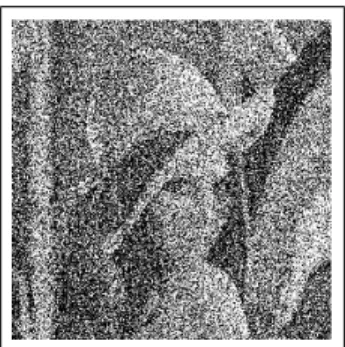
B. Robustness against Compression
In Figure 8 three compressed images which are the JPEG compressed versions of the watermarked image in Figure 6 are presented. Though the images are highly corrupted the watermark is still extracted with 100% success.
In Table III the LPF’s in F B0 has assigned zeros
{−1, 1∠(1 ± 0.01)2π} and F B1 has assigned zeros at
{−1, 1∠(1 ± 0.02)2π}. The first column indicates the JPEG compression quality in percentages, which is established by the quantization table used in the quantization of the discrete cosine transform of the image [14]. The PSNR values after encoding and compression is given in column two. At the last column, the Bit Error Rate (BER) in the decoding phase is presented for the corresponding zero locations and JPEG compression qualities.
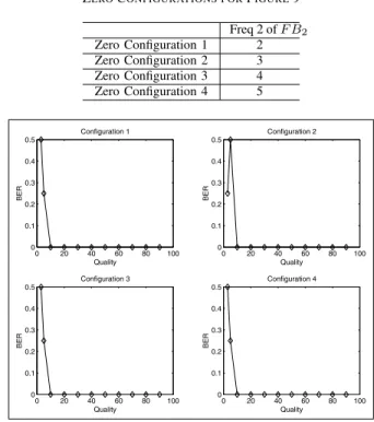
We observe in Table III and Figure 9 that at compression qualities better than 10%, the watermark is extracted perfectly. However, at 10% or 5% compression quality, one wrong bit may be detected in some frames. The success rate at low compression qualities may be improved by employing appropriate assigned zero locations, as we observe in row 12
of Table III. In 9 the assigned zeros of LPF of F B0 are at
{−1, 1∠(1 ± 0.01)2π}and the assigned zeros of F B1 are on
the unit circle and have the arguments indicated in IV-B.
TABLE III
BITERRORRATE ANDPSNRINJPEG COMPRESSEDSIGNAL
Quality PSNR BER 1 90 41.68 0 2 80 35.56 0 3 70 33.73 0 4 60 30.97 0 5 50 29.80 0 6 40 28.75 0 7 30 26.99 0 8 20 24.95 0 9 10 21.79 0 10 5 16.68 %25 11 3 12.30 %50 12 1 11.11 %75
Fig. 8. Compressed images of above watermarked Lena with qualities 20%, 10%, 5%
V. CONCLUSION
Image watermarking via zero assigned filter banks has advantages over the previously proposed techniques in several respects. Under white Gaussian noise and compression attacks, the proposed method improves both PSNR properties in comparison to [5], [8], and [1]. The degradations caused by encoding is much less and the method is more robust against compression and when exposed to high white Gaussian noise. Compared to the methods which require the storage of the watermark, original signal or several additional security keys, this scheme proposes a much more efficient algorithm in the sense that except the assigned zero locations, stage number, frame size and zero tree root locations, no extra information need be stored. The root locations matrix is a binary one and the larger the number L of stages used in the wavelet decomposition, the smaller it gets in size. Even if the stage number, the frame size, and the root location matrices somehow became available to a pirate, it is still impossible to predict the security keys from the marked signal without access to assigned zero locations in the filter banks.
One improvement over our previously reported audio watermarking technique is that, since the zero tree coefficients of the wavelet decomposed signal are replaced with a chosen embedded intensity during encoding, the method here is more robust with respect to assigned zero locations in the filter banks. We continue to explore more robust watermarking schemes both for audio and image signals.
REFERENCES
[1] P. Bao and X. Ma, “Image adaptive watermarking using wavelet domain singular value decomposition,” IEEE Transactions on Circuits and
TABLE IV
ZEROCONFIGURATIONS FORFIGURE9
Freq 2 of F B2 Zero Configuration 1 2 Zero Configuration 2 3 Zero Configuration 3 4 Zero Configuration 4 5 0 20 40 60 80 100 0 0.1 0.2 0.3 0.4 0.5 Quality BER Configuration 1 0 20 40 60 80 100 0 0.1 0.2 0.3 0.4 0.5 Quality BER Configuration 2 0 20 40 60 80 100 0 0.1 0.2 0.3 0.4 0.5 Quality BER Configuration 3 0 20 40 60 80 100 0 0.1 0.2 0.3 0.4 0.5 Quality BER Configuration 4
Fig. 9. Quality vs Bit Error Rate
Systems for Video Technology,15, pp. 96-102, 2005
[2] M. Hsiesh, D. Tseng, and Y. Huang, “Hiding digital watermarks using multiresolution wavelet transform”, IEEE Transactions on Industrial
Electronics, 48, pp. 875-882, 2001
[3] J. Shapiro, “Embedded image coding Using zerotrees of wavelet coef-ficients”, IEEE Transactions on Signal Processing, 41, pp. 3445-3461, 1993
[4] P.P. Vaidyanathan, Multirate Systems and Filter Banks, Prentice Hall, Enlewood Cliffs, NJ, 1993
[5] A. Miyazaki, “On the evaluation of wavelet filter banks for wavelet-based image watermarking,”Proceedings of the 3rd International
Sym-posium on Image and Signal Processing and Analysis, 2003. ISPA 2003,
2, pp. 877-882, 2003
[6] I. Cox, J. Kilian, T. Leighton, and T. Shamoon, “Secure spread spectrum watermarking for multimedia,” IEEE Transactions on Image Processing, 6, pp. 1673-1687, 1997
[7] H. Inoue, A. Miyazaki, and T. Katsura, “An image watermarking method based on the wavelet transform,” 1999 International Conference on
Image Processing, ICIP 99 Proceedings, 1, pp. 296-300, 1999
[8] H. Inoue, A. Miyazaki, and T. Katsura, “A Digital Watermark for Images Using the Wavelet Transform,” Integrated Computer-Aided Engineering, 7, pp. 105-115, 2000
[9] H. Inoue, A. Miyazaki, A. Yamamoto, and T. Katsura, “Multimedia data-embedding and watermarking technologies,” Proceedings of IEEE, 2, pp. 391-395, 1998
[10] M. Swanson, M. Kobayashi, and A. Tewfik, “A digital watermark based on the wavelet transform and its robustness on image compression,” 1998
International Conference on Image Processing, ICIP 98 Proceedings,
86, pp. 1064-1087, 1998
[11] M. Akbas, Zero Assigned Filter Banks and Wavelets, M.Sc. Thesis,The Department of Electrical and Electronics Engineering, Bilkent Univer-sity, 2001
[12] Z. Y¨ucel and A. B. ¨Ozg¨uler, “An audio watermarking algorithm via zero assigned filter banks,” European Signal Processing Conference
EUSIPCO 2005, 2005
[13] X. Xia, C.G. Boncelet, and G.R. Arce, “A multiresolution watermark for digital Images,” Proc. IEEE Int. Conf. on Image Processing, pp. 548-551, 1997
[14] G. Wallace, “The JPEG Still Picture Compression Standart,” IEEE
Transactions on Consumer Electronics, pp. 18-34, 1992
[15] I. Daubechies, Ten Lectures on Wavelets, SIAM, Philadelphia, 1992 368