Anamorphic fractional Fourier transform:
optical implementation and applications
David Mendlovic, Yigal Bitran, Rainer G. Dorsch, Carlos Ferreira, Javier Garcia,
and Haldun M. Ozaktaz
An additional degree of freedom is introduced to fractional-Fourier-transform systems by use of anamorphic optics. A different fractional Fourier order along the orthogonal principal directions is performed. A laboratory experimental system shows preliminary results that demonstrate the proposed theory. Applications such as anamorphic fractional correlation and multiplexing in fractional domains are briefly suggested.
Key words: Anamorphic systems, fractional Fourier transform, optical signal processing.
r1995 Optical Society of America
1. Introduction
Anamorphic systems are well known and widely used for various special systems. The so-called astigmatic processor was exploited in optical data processing as a device for one-dimensional11-D2 Fourier transforming and imaging in two mutually perpendicular direc-tions.1,2 Later, the idea of obtaining a nonsymmetri-cal Fourier transform with crossed cylindrinonsymmetri-cal lenses of different focal lengths working under plane-wave illumination was presented.3 Based on this idea, an anamorphic two-dimensional 12-D2 optical processor was designed.4 In order to extend the performance of the nonsymmetrical Fourier transformer, Andres et
al.5proposed the use of spherical-wave illumination. In this case, with a two-crossed-cylindrical-lenses setup it is possible to obtain an exact Fourier trans-form and a greater angular-magnification coefficient. Based on the nonsymmetrical Fourier transformer working under spherical-beam illumination, a matched-filter anamorphic correlator with improved angular discrimination was suggested6and was also implemented with multiple matched filters for remov-ing possible ambiguities in the recognition process
1see, for example, Ref. 72. In Ref. 8, the anamorphic processor was applied for obtaining fine pseudocolor-ing encodpseudocolor-ing.
We investigate the application of the anamorphic approach to fractional-Fourier-transform 1FRT2 sys-tems. The FRT was recently applied to optical appli-cations by two different definitions: one based on the Wigner-distribution transformation9and the other on the propagation in a graded-index medium.10 It was shown that both definitions are equivalent.11 The FRT operation offers a considerable number of new applications. Some of them are discussed in Ref. 12. The combination of an FRT system and anamorphic optics could result in a system that performs an FRT operation with two different fractional orders along the two main axes. This capability, which consider-ably extends the number of applications of FRT systems, was cited in Ref. 9 but was not elaborated on. In Section 2 the basic details regarding the FRT definition according to the Wigner-distribution trans-formation are given. Section 3 shows the anamor-phic optical setup for performing a nonsymmetrical FRT; the relevant mathematical expressions for de-signing the optical setup are given. In Section 4 we show computer simulations with laboratory experi-mental results that demonstrate the feasibility of the suggested system. In Section 5 a list of applications is suggested.
2. Fractional Fourier Transform and its Relation to the Wigner Distribution
Based on the Wigner-distribution chart definition, the FRT with order P of an input function u1x2 was
D. Mendlovic, Y. Bitran, and R. G. Dorsch are with the Faculty of Engineering, Tel Aviv University, Tel Aviv 69978, Israel. C. Fer-reira and J. Garcia are with the Departamento Interuniversitario de Optica, Universitat de Vale`ncia, Burjassot 46100, Spain. H. M. Ozaktaz is with the Department of Electrical Engineering, Bilkent University, Bilkent 06533, Turkey.
Received 27 February 1995; revised manuscript received 17 July 1995.
0003-6935@95@327451-06$06.00@0.
defined as follows.9 Performing the Pth FRT opera-tion corresponds to rotating the Wigner distribuopera-tion of u1x2 by an angle
f 5 Pp
2 112
in the clockwise direction. On the basis of this definition, Lohmann showed that the bulk-optics sys-tem of Fig. 1 performs FRT’s of order P provided that the following parameters are used:
f 5 f1 Q, 122 Z 5 Rf1, 132 where R 5 tan
1
f 22
, 142 Q 5 sin1f2, 152 and f1 is a constant, which connects the spatialfrequency with the spatial coordinate in the FRT plane.
By analyzing the propagation of the input signal
u1x2 through the optical system of Fig. 1, one could write explicitly the FRT operation of order P, FP,
which is the amplitude distribution in the plane defined for the x1axis, as
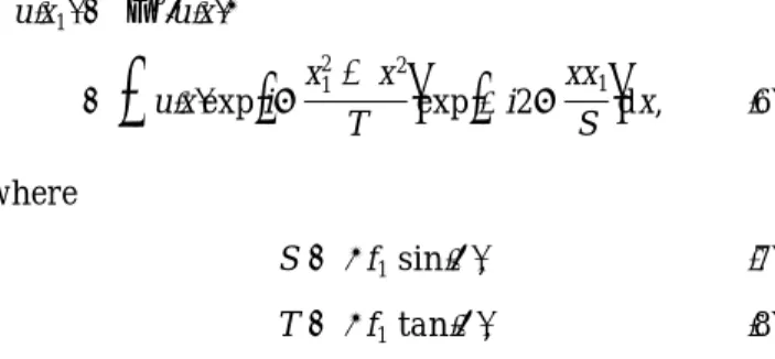
u1x12 5 FP5u1x26 5
e
u1x2exp1
ipx1 21 x2 T2
exp1
2i2p xx1 S2
dx, 162 where S 5 l f1sin1f2, 172 T 5 l f1tan1f2, 182 Note that although the above derivations are given for 1-D objects, the generalization to 2-D objects can be done as shown in Ref. 9.3. Anamorphic Fractional-Fourier-Transform System The bulk-optics optical system of Fig. 1 was extended for performing nonsymmetrical FRT operations by use of anamorphic optics. We assumed that the system should perform an FRT of order Pxalong the
x-axis direction and an FRT of order Py along the y
axis. For simplicity, it was also assumed that
Py, Px. 192
The suggested system for performing the nonsym-metrical FRT is shown in Fig. 2. It contains a symmetrical part for performing the FRT of order Py,
which is exactly the same as that in Fig. 1. Then an anamorphic part was added. In this part, along the x axis, a FRT of order Px2 Pyis performed, while along
the y axis, two imaging operations are done. Note
Fig. 1. Optical setup for performing a FRT.
that an imaging operation means a FRT of order 2; thus two imaging operations gives a FRT of order 4, which is the self-Fourier order.13
Now we deal with the anamorphic part of the system. For performing the x-direction FRT, a cylin-drical lens with focal length fxis placed as shown in
Fig. 2. This lens is active only along the x axis. In the y direction two imaging operations are obtained with two identical lenses with a focal length fy. One
can notice that imaging with lateral magnification equal to 1 is obtained only if the distance between the output of the symmetrical system and the output plane is 8fy. The system can be shortened to 4fyif a
lateral magnification of 21 is admitted. Analogous to Eq.112, we have
f8 51Px2 Py2p@2. 1102
Thus, owing to Eq.132, one can write 4fy5 Rxf15 f1tan
1
f8 2
2
. 1112
Equations122 and 132 lead to
fx5 f1@sin1f82, 1122
Zx5 Rxf1. 1132 Note that f1 is the same constant that was used for calculating the symmetric part of the system. This provides the same spatial coordinates scale in both axes.
Based on the knowledge of f1and f8, and given the lens parameters fyand fx, the output of the
anamor-phic system when the object u1x, y2 is placed at the input plane is u1x2, y22 5 Fx Px Fy Py5u1x, y26 5
ee
u1x, y2exp31
ipx2 21 x2 Tx2
11
ipy2 21 y2 Ty24
3 exp1
2i2pxx2 Sx 2 i2p yy2 Sy2
dxdy, 1142 and Tx, Ty, Sx, and Syare calculated according to Eqs.172 and 182 with
fx5 Pxp@2, 1152 fy5 Pyp@2. 1162
4. Simulation and Experimental Results
The suggested anamorphic processor was simulated by computer and experimentally demonstrated. For the computer simulations,MATLABsoftware for
simu-lating the integral of Eq.1142 was written. Note that it involves a 2-D integral that contains a chirp factor, which requires a huge number of calculations. Thus the estimation of this integral was done by use of a more efficient procedure that is based on the gradient-index medium definition of the FRT.10 Figure 31a2
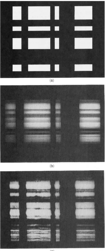
shows the input pattern that was used for the simula-tion. The order Px 5 0.667 and Py 5 0 was used.
Figure 31b2 depicts the corresponding simulation re-sult.
An optical setup similar to the one in Fig. 2 was constructed. In order to eliminate a cylindrical lens, we used a setup that performs Py5 2. That is, along Fig. 3. 1a2 Input pattern used in experiments, 1b2 anamorphic FRT of orders Px5 0.667 and Py 5 0 calculated digitally, and
the y direction, we perform an imaging with inversion. In this way, the optical setup contains only two cylindrical lenses. In our case, the lenses were with focal lengths of 304.8 mm for the x direction and 76.2 mm for the y direction. Again, the pattern of Fig. 31a2 was used as input. The obtained output is presented in Fig. 31c2. A fair agreement between the simulation and the laboratory experiment is obtained. Nevertheless, note that the aspect ratio of the com-puter simulation and the experimental results is not the same.
5. Applications
A. Anamorphic Fractional Correlation
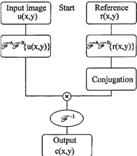
Based on the symmetric FRT, various definitions for the fractional correlation operation were suggested in Ref. 14. It was shown that the fractional correlation is a useful tool for shift-variant pattern recognition and for object localization. Below, we suggest the extension of the fractional correlation definition also to anamorphic fractional orders. If we take into account the conclusion of Ref. 14 that the amount of the shift-variance property could be controlled by the fractional order, the motivation of this anamorphic definition might be a system that has different shift-invariant properties along the two main axes. For instance, when letters written in an x direction line should be recognized, the shift-invariant property along the y direction is not necessary, and we can save it for improving the noise performance of the system. Figure 4 shows a block diagram of the algorithm for performing an anamorphic fractional correlation. It contains the filter generation procedure and the fractional correlation itself. Note that this proce-dure is based on the first definition that was given in Ref. 14. Anamorphic implementations of the other definitions can be done in a similar way.
B. Efficient Multiplexing
In many practical cases a single transmission line is used to transmit several signals packed together. Multiplexing techniques permit the signal compres-sion for the transmiscompres-sion. An analogous situation arises when several signals are to be stored in a recording medium. In these cases it is important to use in the most efficient way the space–bandwidth product of the recording medium or the transmission line, which permits the transmission of the maximum possible amount of information. Two typical ways for multiplexing are in the space and in the frequency domains. In the first case the signals are split into spatial1or temporal2 pieces, which are interleaved for several signals in space 1time2 sequence. For fre-quency multiplexing the process is based on adding a bias frequency that is different for every signal, which ensures that the spectra do not overlap. In this case several signals can share the same space without cross talk. The procedure may be easily extended to both space- and frequency-domain multiplexing. The useful area of the transmission line, defined by the aperture of the system and the bandwidth, may be covered by signals of smaller extent.
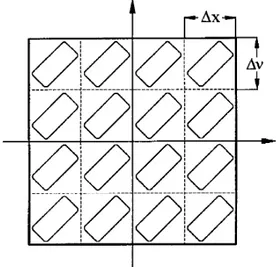
The multiplexing can be easily illustrated for 1-D signals in the Wigner-distribution space. This joint representation involves simultaneously the space and the frequency domains. The space and the fre-quency cutoff of the system or transmission line defines a rectangular area1DXTotal, DnTotal2, which lim-its the signals that are input into the system. Analogously, every signal may be circumscribed in a rectangle of dimensions 1Dx, Dn2. The packing of signals in the Wigner space consists of shifting every signal, creating an array inside the bandwidth of the system. An example is shown in Fig. 5 for the 1-D case.
Nevertheless, this packing procedure, which uses the space and the frequency bandwidths of the signal, is not always the most efficient one. In many cases,
Fig. 4. Block diagram showing the fractional correlation proce-dure.
Fig. 5. Space and frequency multiplexing of the signals when the main axes of their domains are aligned with the1x, n2 axes.
the domain of the signal does not fully cover the rectangle defined by 1Dx, Dn2. The previously de-scribed procedure for packing will result in a wasting of the transmission capacity of the system. An ex-ample is depicted in Fig. 6. In this situation a rectangle oblique to the1x, n2 axes would include the signal domain more accurately. This can be accom-plished by rotation of the Wigner distribution of each signal before multiplexing. Then, adding a bias fre-quency and shifting every signal, one would obtain an arrangement analogous to that of Fig. 5. As men-tioned in Section 1, a FRT of order P produces a rotation of the Wigner distribution by an angle f 5
P1p@22. The procedure for demultiplexing would in-volve a FRT of order 2P for every signal. The generalization for 2-D signals is straightforward.
For the case of 2-D signals, if a symmetric optical system is used for performing the FRT, the order of the transformation is the same for both axes. A much greater flexibility is provided if an anamorphic system is used. In this case, it is possible to render a different-order FRT for each variable. The conse-quent four-dimensional rotation in the Wigner space may adjust the domain of the signal to the axis of the transmission line in a more accurate way. It is worth noting that the rotation can be distinct for every signal. Extension to nonequally spaced distribu-tions of signals in the Wigner space is also possible.
C. Anamorphic Chirp Filtering
A common use of the Fourier transform is its use in spatial filtering. A simple case is that with an image corrupted with an additive single-frequency noise. The filtering of the Fourier transform with two small stops removes this noise without significantly alter-ing the image. More complicated is the case in which the noise does not consist of a single frequency. A particular case that arises in some practical situa-tions is the chirp noise. It consists of a signal with a spatially variable linear frequency, represented, for instance, by u1x2 5 sin1kx22. It may appear as a
result of the interference of two spherical beams with different curvatures. This signal is not well located in either space or frequency domains, being, in prac-tice, impossible to remove in any of these spaces by spatial filtering without the image being severely altered. A FRT can solve this problem. The reason is that a chirp signal has a Wigner distribution that is concentrated in a line in the1x, n2 space. Rotating it so that the line is perpendicular to the x axis, we can again obtain a spatial filtering by using a small stop. Recovery of the filtered image would involve an inverse FRT of the same order.
In the 2-D case, chirp noise with distinct character-istics in both spatial axes may appear. If the param-eters of the chirps are not the same, a different rotation of the Wigner distribution may be needed to filter out each chirp noise. In a symmetric system, this would involve filtering in two different planes corresponding to different fractional orders. The use of anamorphic optics introduces the possibility of performing a different FRT for two orthogonal axes. The system can simultaneously filter two chirp noises with different characteristics.
6. Conclusions
In this paper the anamorphic fractional Fourier trans-form was optically implemented by means of a setup that contains cylindrical lenses. Such an anamor-phic transform can increase the flexibility of the optical system. The degree of fractional Fourier transform can be set independently for two perpen-dicular directions. This provides the possibility of acting in different fractional domains in these axes. Experimental results match well with computer simu-lations. Finally, some applications of anamorphic fractional systems such as anamorphic fractional correlation and multiplexing in the fractional domain are suggested.
This work was partially supported by the Comisio´n Interministerial de Ciencia y Tecnologı´a, Spain, under grant TAP93-0667-C03-03. Rainer Dorsch is on leave from Angewandte Optik, Physikalisches Insti-tut, Erlangen University, Germany. Fruitful discus-sions with Adolf W. Lohmann are gratefully acknowl-edged.
References
1. J. W. Goodman, Introduction to Fourier Optics1McGraw-Hill, New York, 19682.
2. L. J. Cutrona, E. N. Leith, C. J. Palermo, and L. J. Porcello, ‘‘Optical data processing and filtering systems,’’ IRE Trans. Inf. Theory IT-6, 386–400119602.
3. T. Szoplik, W. Kosek, and C. Ferreira, ‘‘Nonsymmetric Fourier transforming with an anamorphic system,’’ Appl. Opt. 23, 905–909119842.
4. T. Szoplik and H. H. Arsenault, ‘‘Rotation-variant optical data processing using the 2-D nonsymmetrical Fourier transform,’’ Appl. Opt. 24, 168–174119852.
5. P. Andres, C. Ferreira, and E. Bonet, ‘‘Fraunhofer diffraction patterns from apertures illuminated with nonparallel light in nonsymmetrical Fourier transformers,’’ Appl. Opt. 24, 1549– 1552119852.
Fig. 6. Inefficient multiplexing of signals with the domains not aligned with the1x, n2 axes.
6. E. Bonet, C. Ferreira, P. Andres, and A. Pons, ‘‘Nonsymmetri-cal Fourier correlator to increase the angular discrimination in character recognition,’’ Opt. Commun. 53, 155–160119862. 7. C. Ferreira and C. Vazquez, ‘‘Anamorphic multiple matched
filter for character recognition performance with signal of equal size,’’ J. Mod. Opt. 37, 1343–1354119902.
8. M. S. Millan, C. Ferreira, A. Pons, and P. Andres, ‘‘Application of anamorphic systems to directional pseusocolor encoding,’’ Opt. Eng. 27, 129–134119882.
9. A. W. Lohmann, ‘‘Image rotation, Wigner rotation, and the fractional Fourier transform,’’ J. Opt. Soc. Am. A 10, 2181– 2186119932.
10. D. Mendlovic and H. M. Ozaktas, ‘‘Fractional Fourier
trans-forms and their optical implementation: I,’’ J. Opt. Soc. Am. A
10, 1875–1881119932.
11. D. Mendlovic, H. M. Ozaktas, and A. W. Lohmann, ‘‘Graded-index fibers, Wigner-distribution functions, and the fractional Fourier transform,’’ Appl. Opt. 33, 6188–6193119942.
12. H. M. Ozaktas, B. Barshan, D. Mendlovic, and L. Onural, ‘‘Convolution, filtering, and multiplexing in fractional Fourier domains and their relation to chirp and wavelet transforms,’’ J. Opt. Soc. Am. A 11, 547–559119942.
13. A. W. Lohmann and D. Mendlovic, ‘‘Self-Fourier objects and other self-transform objects,’’ J. Opt. Soc. Am. A 9, 2009–2012 119922.
14. D. Mendlovic, H. M. Ozaktaz, and A. W. Lohmann, ‘‘Fractional correlation,’’ Appl. Opt. 34, 303–309119952.