Observation of off-axis directional beaming via subwavelength asymmetric metallic gratings
Tam metin
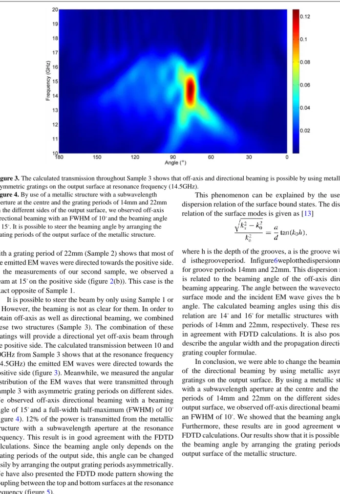
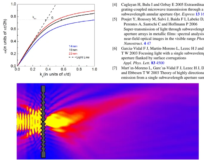
Şekil

Benzer Belgeler
She is a member of the international Association of Computing Machinery Committee on Women in Computing, co-founder of the regional New York Celebration of Women in Computing
Turkish Republic of Northern Cyprus Public Information Office, Cyprus Turkish Press History (K ıbrıs T€urk Bas ınının Tarihi); Turkish Cypriot Journalists Association (Kıbrıs
In conclu sion, hyp er-reality of a three-d im ensional cinem atic exp erience w ithin p ostm od ern era is u nd er the concern of the social context rather than
All of these brings us to main subject of this chapter where we flourish the basic characteristics of 1-body interactions, HFI and QI namely, to develop profound understanding
When the current density increases to 70 A/cm 2 , the radiative recombination rates in the 3rd, 4th, and 5th QWs have been enhanced in the GTQB LED more significantly than those in
This study uses single point diamond turning tests with cham- fered diamond tools together with areal surface characteriza- tion and subsurface damage detection techniques to
group, cytoplasmic immunoreactivity was observed in the hepatocytes throughout the liver sections (Fig. This immunoreactivity was stronger in hepatocytes located close to the
She would then ask questions that prompt children to think deeply about the new words as they play: “I can’t find the rake, do you think a shovel will work to pick the
