Near-
field light localization using subwavelength apertures incorporated
with metamaterials
Damla Ates
⁎
,1, Atilla Ozgur Cakmak
1, Ekmel Ozbay
Nanotechnology Research Center, Department of Physics, Department of Electrical and Electronics Engineering, Bilkent University, 06800 Ankara, Turkey
a b s t r a c t
a r t i c l e i n f o
Article history:
Received 1 November 2011 Accepted 28 February 2012 Available online 12 March 2012 Keywords:
Electromagnetic wave transmission Diffraction, grating and apertures Metamaterials
Resonators
We report strong near-field electromagnetic localization by using subwavelength apertures and metamater-ials that operate at microwave frequencies. We designed split ring resonators with distinct configurations in order to obtain extraordinary transmission results. Furthermore, we analyzed thefield localization and focus-ing characteristics of the transmitted evanescent waves. The employed metamaterial configurations yielded an improvement on the transmission efficiency on the order of 27 dB and 50 dB for the deep subwavelength apertures. The metamaterial loaded apertures are considered as a total system that offered spot size conver-sion ratios as high as 7.12 and 9.11 for the corresponding metamaterial configurations. The proposed system is shown to intensify the electricfields of the source located in the near-field. It also narrows down the elec-tromagnetic waves such that a full width at half maximum value ofλ/29 is obtained.
© 2012 Elsevier B.V. All rights reserved.
1. Introduction
The transmission characteristics of light through apertures have been the subject of the studies for a long time. The earlier explana-tions based on the Kirchhoff scalar diffraction theory gave good re-sults as long as the opening attained comparably larger values with respect to the operational wavelength, λ. In 1940s, H. Bethe addressed the shortcomings of the Kirchhoff scalar diffraction theory and developed a new approach that attempted to elucidate the elec-tromagnetic wave transmission for the subwavelength apertures[1]. According to Bethe, the transmission efficiency scaled as (r/λ)4for
an infinitesimally thin metallic screen with perfectly conducting walls extending to infinity, where r stands for the radius of the sub-wavelength aperture. Both of the theories concentrated on the opa-que screens that were constituted from the ideal material parameters and excluded the contributions of the evanescent surface waves on the transmission characteristics. It was only after the pio-neering works at the turn of the century which pointed out the possi-bility of an extraordinary transmission through subwavelength aperture arrays that the attention of the scientific community has once again been directed towards the perforated metallic slits[2]. This era also marked the beginning of the scientific debates over the leading mechanisms of the extraordinary transmission. Initially, the extraordinary transmission was associated with the surface-plasmon phenomenon at the dielectric–metal interface at optical wavelengths. Thereafter, several results targeting the extraordinary
transmission started to be reported at microwave frequencies as well as in optical wavelengths[3–7]. The observed surface waves at microwave frequencies are ascribed to the designer surface plasmons that exist due to the modification of the surface impedance by making use of the pure geometrical parameters[8]. Moreover, the researchers have investigated the effect of periodicity and size of the hole arrays. Scientists designed corrugations around the apertures and surfaces to establish an improved coupling[9,10]. The accumulated theoretical and experimental experiences enabled the extraordinary transmis-sion to be attributed to the coupling of the leaky surface waves at both ends of the aperture through the evanescent waveguide modes of the subwavelength opening. The corrugated surfaces increased the transmission and provided better coupling conditions. Alterna-tively, Alu et al. suggested covering the aperture with a metamaterial slab in order to achieve superior coupling efficiencies [11]. On the other hand, Bilotti et al. proposed exploiting the resonance character-istics of the metamaterials, which in turn yielded the amplification of the electromagneticfields around the aperture[12]. Since the meta-materials provide thefield localization opportunity in the vicinity of the resonance frequency, they can be considered as a strong candi-date for a prospective corrugation design that boosts the transmission efficiency. Accordingly, Aydin et al. experimentally showed a 740-fold transmission enhancement by inserting a split ring resonator inside the aperture[13]. Then, in one of our previous studies we discussed the physical origins of the enhancement in terms of the induced sur-face currents[14]. Recently, we have demonstrated a 70,000-fold en-hancement experimentally and analyzed the parameters of the designed structure[15].
Independently, the localization theory has been developed in the 1960s and light localization obtained in a wide range of areas from
⁎ Corresponding author. Tel.: +90 5366526719. E-mail address:[email protected](D. Ates).
1The authors equally contributed.
0030-4018/$– see front matter © 2012 Elsevier B.V. All rights reserved. doi:10.1016/j.optcom.2012.02.102
Contents lists available atSciVerse ScienceDirect
Optics Communications
lasers to photonic crystals and gratings has gained a significant inter-est from the scientific community in the recent years[16,17]. One of the most striking ways to localizefields is using metamaterials. Nano-wire metamaterial designs and asymmetrical split ring resonators were employed to localize the electricfields[18–20]. Cavities that re-semble the counterparts in photonic crystal literature are utilized to confine the electromagnetic waves[21,22]. Conversely, there have been attempts to localize thefields outside the metamaterial speci-men. This subject has beenfirst attended by Pendry et al. under the topic of super lenses[23]. N. Fang and X. Zhang considered the imag-ing properties of the metamaterial super lenses and observed that the evanescent waves are strengthened at the exit side[24]. Furthermore, scientists such as Grbic et al. treated the negative index lens as a transmission line to realize the subdiffraction imaging[25]. Aydın et al. has achieved a strong localization by focusing the evanescent waves with the aid of negative index materials[26].
For the purposes of this paper we will be mainly concentrated on thefield localization at the output side of a subwavelength hole and a subwavelength slit incorporated with two distinct metamaterial de-signs. The localized beam already results in extraordinary transmis-sion. Firstly, the transmission mechanism offered by using two different metamaterial configurations will be discussed. Secondly, the confinement capabilities of the proposed structures will be inves-tigated and compared.
2. Split ring resonator configurations
A single resonator embedded close to a subwavelength aperture is the key element in elevating the electromagneticfields and will com-prise the fundamental building block for the subwavelengthfield lo-calization. The first configuration is illustrated in Fig. 1(a). The zoomed perspectives are also shown for convenience. The split ring
resonator (SRR) is carefully aligned at the midpoint of the aperture such that the gaps of the SRR, gSRRare parallel to y-axis. The
propaga-tion direcpropaga-tion is z-axis and the aperture is illuminated with a wave-guide in the experiments. This particular wavewave-guide is modeled in CST Microwave Studio and shown in gray color. The aperture has a ra-dius Raperture= 4 mm and resides on a square plate with a width
W = 200 mm. The SRR gaps are gSRR= 0.2 mm, while the inner and
outer radius of the structure are rSRR= 2.7 mm and RSRR= 3.6 mm.
The metal width is wSRR= 0.9 mm.
Subsequently, we have designed split ring resonators that have connecting bars and the configuration is depicted inFig. 1(b). These connected SRRs are labeled as CSRR. The samples are fabricated in a similar way to the previous design. They are deposited on a dielectric printed circuit board (PCB) with a 1.6 mm thickness. The connected bar length is lCSRR= 5.5 mm. The remaining parameters for the
indi-vidual SRRs are gCSRR= wCSRR= 0.5 mm, and rCSRR= 3.5 mm, R-CSRR= 5.5 mm. The area of the rectangular aperture is 3 × 7.5 mm2.
The CSRR is inserted midway into the aperture. The thicknesses of the deposited copper are the same in both configurations and it is equal to 30μm.
The resonance frequencies of the regarding resonators are shown inFig. 1(c). The launched beam has an electricfield component paral-lel to y-axis. Then, the gap of the SRR captures the incoming electric field which induces circulating currents and creates accumulated charges at the resonance condition. A similar action will take place for CSRR which will only result in smaller resonance strength in con-trast to the single SRR. The effect of shortening the SRRs destroys the charge accumulation at the resonance frequency. As it can be seen fromFig. 1(c), the shortened SRRs in CSRR do not totally lose their resonance owing to the fact that shortening is performed over a lon-ger path. Nevertheless, a significant portion of the charges will leak away through the connection bars. One might also wonder the overall shallow depths of the transmission results. The attained S21results
are one order of magnitude higher (in dB scale) than the usually
inspected values for conventional SRRs around the resonance fre-quency. Given that a single resonator will be positioned around the aperture in the proceeding sections, the transmission characteristics have been investigated for a single SRR in order to avoid the contribu-tions coming from the coupling mechanisms in a SRR array. There-fore, the SRR and CSRR are illuminated with a beam offinite width that can circumvent the resonators and reach the detector. Periodic boundary conditions are not allowed in the simulations. Consequent-ly, the resonators could capture a limited amount of the propagating waves. Yet, we obtain the individual resonance frequencies of our configurations as fSRR= 3.27 GHz and fCSRR= 3.33 GHz.
3. Transmission enhancement phenomenon
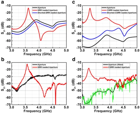
Once the resonator is placed in the vicinity of the subwavelength aperture simulated and measured transmission characteristics are plotted inFig. 2(a) and (b) for the SRR configuration, respectively. The transmission enhancement frequency turned out to be 3.6 GHz in the simulation results, whereas a peak is spotted at 3.56 GHz in the experiments. There is a good agreement between the experimen-tal and simulation based results in terms of the general transmission characteristics. This subwavelength aperture has a cutoff frequency for the lowest allowed modes at almost 22 GHz. Then, the aperture can be visualized as a LC tank with a dominant inductive character which forces the opening to act as a high passfilter[27]. According to Bethe, we would anticipate a dramatically weak transmission at the output of the subwavelength aperture in the absence of the reso-nator. Instead of the electrically large cover suggested by Alu et al. in Ref.[11], we make use of the resonance mechanism of a single nega-tive material as pointed out in Ref.[12]. It was indicated in Ref.[12] that only the effective permeability would be the determining consti-tutive parameter and a transmission enhancement could also be sus-tained at another frequency where the reduced permeabilityμ=−1 is feasible. However, the detected transmission enhancement is solely
Fig. 2. Transmission spectra of the (a) simulated results for the single aperture (black line), the SRR loaded aperture (red line), and the shortened SRR loaded aperture (blue line); (b) measurement results for the single aperture (black line) and the SRR loaded aperture (red line); (c) simulation results for the single aperture (black line), the CSRR loaded ap-erture (red line) and the shortened CSRR loaded apap-erture (blue line); and (d) measurement results for the single apap-erture (green line) [the measurement result isfitted to a curve (black line) because of the sudden ripples] and the CSRR loaded aperture (red line).
due to the induced resonance of the SRR for our configuration which offers approximately a 27 dB improvement in the transmission fig-ures on top of the subwavelength aperture. A parallel magnetic dipole and a perpendicular electric dipole (with respect to the screen) are the responsible dipole moments for the transmission through the subwavelength opening. In our current configuration, the strong di-pole moments are along y-axis for the electric and z-axis for the mag-netic counterpart. Thus, we do not have a chance to elevate drastically the amplitudes of the original dipole moments of the subwavelength aperture around the resonance frequency. Nonetheless, the induced dipoles in the SRR cancel out the equivalent dipole of the subwave-length aperture in the neighborhood of the transmission enhance-ment frequency owing to the bianisotropy of the SRR, as indicated in Ref.[28]. Thus, we encounter a dip in the transmission graph inside the band starting from 4 GHz up to 4.5 GHz. Finally, the shortened SRR loses its magnetic resonance and causes an augmentation in the lossfigures, which further verifies the resonance based explanations. In the meantime, the transmission characteristics have been laid out for the CSRRs inFig. 2(c) and (d). The cutoff wavelength of the slit is at even higher frequencies (42.8 GHz). As a result, smaller amount of transmission is detected for the subwavelength aperture case. The experiments are carried out with horn antennas connected to HP 8510C Network Analyzer. Absorbers have been placed in order to minimize the diffractions at the edges of the metallic screen, which can easily outbalance the main signal. Such effects trigger the ripples in the measured results inFig. 2(d). Similar scenarios had been inves-tigated in Ref.[15]. In contrast to the real life problem, we can numer-ically tackle this particular difficulty with perfectly absorbing boundaries. The resonance mechanism presents a transmission en-hancement higher than 50 dB at the enen-hancement frequency of 3.28 GHz. Now, the transmission mechanism depends on the con-nected bars and we do not detect a transmission dip just after the en-hancement frequency. The transmissionfigures stay improved over 20 dB with the addition of the CSRR on top of the single slit transmis-sion. Lastly, the CSRR had been shortened from the midpoint of the connecting bars. In the end, this shortening of the connecting bars proved to have a comparable influence on the transmission spectra by destroying the magnetic resonance of the individual SRRs.
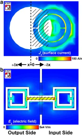
Fig. 3is presented in order to shed light to the underlying physical mechanisms of the transmission enhancement phenomenon. The in-duced surface currents in the vicinity of the aperture are illustrated at the resonance frequency inFig. 3(a). Then, the addition of the SRR strengthens an electric dipole along the y-axis. However, this induced dipole and thereby the induced surface currents are nullified at a cer-tain degree by the image current formation on the metallic screen, as shown inFig. 3(a). Consequently, the shaded area will be the main contributor of the induced currents whose function will be to trans-mit the impingingfield to the exit side. In other words, the shaded area will play the role of an effective aperture for an ordinary anten-na. In a very general manner the effective aperture of an antenna is defined as Aeff= Pout/Pinc= Gλ2/4π, where Pout is the delivered
power by the antenna, Pincis the incident power in terms of watts
per unit area and G is the antenna power gain. The effective aperture is proportional to the operational wavelength. The SRR together with the aperture constitutes a new transmission system. This is the main reason behind the mismatch between the given resonance frequency of the isolated SRR (seeFig. 1(c)) and the transmission enhancement frequency of the total system. Such a shift has also been reported in Ref.[12]. Unlike the cases in the earlier studies[12–14]the SRR's res-onance is not magnetically excited and the SRR is directly facing the metal screen. These factors found the ground for a more pronounced shift to be observed between the self-resonance frequency and the transmission enhancement frequency. Then, an alteration of the exact location of the SRR directly determines the enhancement fre-quency. We have not observed a strong difference between the ex-perimental and numerical values but a small misalignment would
be likely to produce quite different transmission characteristics. Ref. [14] considered the misalignments only in one dimension and showed that a shift of δx1=−0.1 mm and δx2= +0.3 mm would
move the transmission enhancement frequency to the higher and lower frequencies from its original location respectively, as predicted from the qualitative effective aperture discussions. The transmission enhancement values attained lowerfigures for those cases, since the maximum electric dipole can be induced when the SRR is carefully positioned at the midpoint of the aperture assuming that the aperture is perfectly aligned with the incoming illumination. The other way of modifying the effective aperture size of the system is to tune the radi-us of the opening. It was also depicted in Ref.[14]that the transmis-sion enhancement frequencies spanned a band from 3.3 GHz to 6 GHz for the corresponding aperture radii ranging from 2.8 mm up to 7 mm.
Fig. 3(b) shows the calculated electricfields around the aperture at the designated resonance frequency. The CSRR can be regarded as a loop antenna connecting the two sides of the aperture. The connect-ing bars conduct the induced currents over a broad range of frequen-cy. The induced currents continue to be shared outside the enhancement band. We are comparably much less limited by the res-onance bandwidth of the structure. An electric dipole parallel to the screen is again induced. This time different from the SRR case, a mag-netic dipole parallel to the screen is also excited and the interactions with the screen are comparably reduced. In turn, the transmission en-hancement frequency shifted relatively less from the isolated resona-tor configuration in contrast to the SRR case. We do not have a strong dependency to the geometrical sizes of the aperture. The incoming fields are captured by the loop antenna and the fields are safely guid-ed to the output plane. The shadguid-ed region localizes thefields during the transmission of the electromagnetic fields. Eventually, the
Fig. 3. (a) Induced surface currents on the SRR at f = 3.6 GHz. The shaded region en-compasses the effective aperture of the overall SRR subwavelength aperture system (media 1). (b) The electricfields (Ey) in the vicinity of the subwavelength aperture at
f = 3.28 GHz. The shaded region emphasizes the strong spatial confinement of the elec-tricfields inside the aperture (media 2).
connecting bars play the role of a subwavelength waveguide. The width of this particular waveguide turns out to be as small asλ/180 at the transmission enhancement frequency. Thefields are confined to this deep subwavelength waveguide for a propagation length of λ/18. As it is previously discussed in Ref.[15], the inner loops of the individual SRRs do not play a major part in the transmission enhance-ment. The magnetic dipole is permanently obstructed when the outer loops are shortened and the waveguiding effect of the highly confined electricfields is thereby demolished. At these regarding peaks not only we obtain a high transmission but we also have a chance to lo-calize the evanescent wave at the exit side of the aperture. In the next section, the discussions will be devoted to the examination of these scenarios.
4. Field distributions and highly localized fields at the output plane
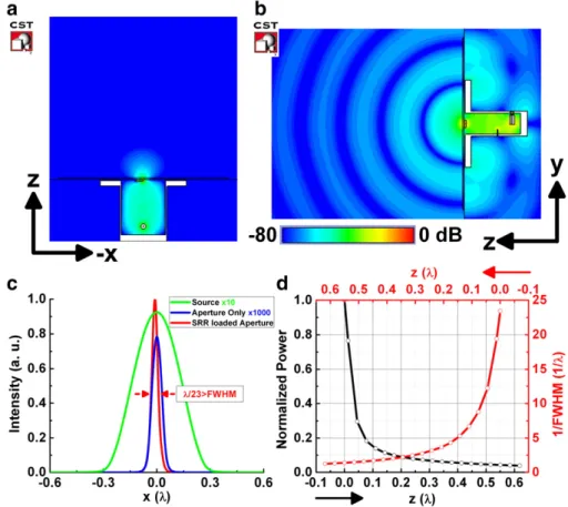
In this part, we analyzed the characteristics of the nearfield local-ization around the resonance frequencies. Thefields at the output side have been numerically collected and presented inFigs. 4 and 5 si-multaneously.Fig. 4entails the SRR loaded subwavelength hole while Fig. 5involves the CSRR incorporated subwavelength slit.Figs. 4(a) and5(a) exhibit thefield distribution on the x–z planes, whereas Figs. 4(b) and5(b) portray thefield distribution on the y–z planes at their respective resonance frequencies in dB scale. All of thefield distributions are normalized with respect to the maximum attained value in the concerning scenarios. The cutoff frequencies of the sub-wavelength hole and slit were calculated to be well below the opera-tional frequency range. The transmittedfields in Figs. 4 and 5are originally the evanescent modes of the subwavelength openings. Therefore, thefields decay dramatically in the direction of propaga-tion. Consequently, intensified fields are localized in the near field
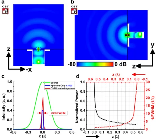
zone of the aperture. Yet, the overall configurations propose to re-strict the transmitted evanescent modes only on the x–z planes. For instance, the loop antenna nature of the CSRR compels thefields to radiate isotropically on the y–z planes, while the radiation is not allowed along the induced magnetic dipole direction (x-axis), which is clearly observed inFig. 5(a)[29]. Accordingly, the field profiles are plotted inFigs. 4(c) and5(c) in order to explore the localization capabilities of the total systems. The minimum realizable full width at half maximum (FWHM) values of the overall systems are revealed asλ/23 and λ/29 for the SRR and CSRR incorporated approaches, re-spectively. The excitation source with FWHM values aroundλ/3 is down converted by taking advantage of the subwavelength resona-tors placed in the reactive nearfield zone of the illumination. Then, the precise beam spot-size conversion values are calculated to be 7.12 and 9.11 for the systems with SRR and CSRR, correspondingly. It might not sound interesting to come across such a focusing effect at the output side of the subwavelength apertures. Nevertheless, the proposed designs have not only amplified the evanescent mode, but also narrowed down the outgoingfields exceeding the capabilities of the subwavelength openings, as shown inFigs. 4(c) and5(c). We numerically integrated the intensity profiles on x–y planes along the direction of propagation (z-axis).Figs. 4(d) and5(d) explicitly dem-onstrate that the power values drop rapidly in the direction of prop-agation. Approximately 10% of the initial power is conserved in the case of SRR loaded apertures while around 20% is preserved for the configuration with the CSRR. On the other hand, when the FWHM values are inspected, λ/5 FWHM is still feasible at a distance of 0.15λ away from the aperture loaded with the SRR. The same FWHM values can be observed in the CSRR at a location 0.1λ away from the metallic screen. The SRR configuration extracts more inten-sity from the subwavelength structure by focusing down the ampli-fied evanescent fields, which can even get higher values than the
Fig. 4. Field distributions on (a) x–z planes (media 3) and (b) y–z planes (media 4) in dB scale at f=3.6 GHz for the SRR loaded aperture. (c) Intensity profiles along the x-axis for the single aperture (blue line), the SRR loaded aperture (red line) and the source in free space (light green). (d) Normalized power (black line) and 1/FWHM values (red line) along the propogation direction (z-axis).
source itself, as it can be seen in thefield profiles ofFig. 4(c). Con-versely, the CSRR structure promises an improved spot size conver-sion ratio when the FWHM values are taken into consideration. 5. Conclusions
Transmission enhancement through subwavelength apertures is still a challenging topic in experimental physics. In this paper, we have demonstrated alternative methods for improving the transmis-sionfigures of the otherwise opaque screens. The resonance nature of the SRR and CSRR is exploited in order to boost the transmission ef-ficiency of the evanescent modes by factors of 27 dB and 50 dB, re-spectively. The physical origins of the extraordinary transmission are discussed in details. It is emphasized that the SRR loaded holes must be regarded as a combined system which has a certain effective aperture size. Through this effective aperture the leaky modes are transmitted to the outer plane. On the other hand, the CSRR loosens the dependency on the geometrical parameters of the aperture while behaving like a loop antenna. The capturedfields are guided via the connecting bars to the exit side. Furthermore, we investigated thefield distributions of the outer plane. The overall system offers spot conversion ratios as high as 7.12 and 9.11 for the SRR and CSRR designs, respectively. FWHM values down toλ/29 are demonstrated numerically in the nearfield of the excitation source by attaching the CSRR to the subwavelength slit.
The proposed designs are simulated and measured at microwave frequencies while bearing in mind the prospective design adaptable for optical wavelengths. An analogy which will be suitable for the op-tical regime would prove tofind essential application fields ranging from sensors, biophotonics, SNOM and subwavelength imaging. The horn antennas have to be replaced with the optical light sources such as lasers. The designer will encounter the additional losses
coming from the material properties of the metals at optical wave-lengths and will have to overcome the difficulties of the nanofabrica-tion. Nevertheless, a careful design is expected to bring numerous novelties on top of the conventional systems for those who are inter-ested in the near-field optics.
Acknowledgment
This work is supported by the projects DPT-HAMIT, EU-PHOME, EU-N4E, NATO-SET-181 and TUBITAK under project nos., 107A004, 107A012 and 109E301. One of the authors (E.O.) also acknowledges partial support from the Turkish Academy of Sciences.
References
[1] H.A. Bethe, Physical Review 66 (1944) 163.
[2] T.W. Ebbesen, H.J. Lezec, H.F. Ghaemi, T. Thio, P.A. Wolff, Nature 391 (1998) 667. [3] L. Martin-Moreno, F.J. Garcia-Vidal, H.J. Lezec, K.M. Pellerin, T. Thio, J.B. Pendry,
T.W. Ebbesen, Physical Review Letters 86 (2001) 1114.
[4] J.A. Porto, F.J. Garcia-Vidal, J.B. Pendry, Physical Review Letters 83 (1999) 2845. [5] K.G. Lee, Q.-H. Park, Physical Review Letters 95 (2005) 103902.
[6] M. Beruete, M. Sorolla, I. Campillo, J.S. Dolado, L. Martin-Moreno, J. Bravo-Abad, F.J. Garcia-Vidal, IEEE Transactions on Antennas and Propagation 53 (6) (2005) 1897.
[7] F.J. Garcia-Vidal, H.J. Lezec, T.W. Ebbesen, L. Martin-Moreno, Physical Review Letters 90 (2003) 213901.
[8] J.B. Pendry, L. Martin-Moreno, F.J. Garcia-Vidal, Science 305 (2004) 847. [9] A. Degiron, T.W. Ebbesen, Optics Express 12 (2004) 3694.
[10] E. Ozbay, Science 311 (5758) (2006) 183.
[11] A. Alu, F. Bilotti, N. Engheta, L. Vegni, IEEE Transactions on Antennas and Propaga-tion 54 (2006) 1632.
[12] F. Bilotti, L. Scorrano, E. Ozbay, L. Vegni, Journal of Optics A: Pure and Applied Optics 11 (2009) 114029.
[13] K. Aydin, A.O. Cakmak, L. Sahin, Z. Li, F. Bilotti, L. Vegni, E. Ozbay, Physical Review Letters 102 (2009) 013904.
[14] A.O. Cakmak, K. Aydin, E. Colak, Z. Li, F. Bilotti, L. Vegni, E. Ozbay, Applied Physics Letters 95 (2009) 052103.
Fig. 5. Field distributions on (a) x–z planes (media 5) and (b) y–z planes (media 6) in dB scale at f=3.28 GHz for the CSRR loaded aperture. (c) Intensity profiles along the x-axis for the single aperture (blue line), the CSRR loaded aperture (red line) and the source in free space (light green). (d) Normalized power (black line) and 1/FWHM values (red line) along the propogation direction (z-axis).
[15] D. Ates, A.O. Cakmak, E. Colak, R. Zhao, C.M. Soukoulis, E. Ozbay, Optics Express 18 (2010) 3952.
[16] X. Jiang, C.M. Soukoulis, Physical Review Letters 85 (2000) 70. [17] X. Jiang, C.M. Soukoulis, Physical Review E 65 (2002) 025601.
[18] T.S. Kao, F.M. Huang, Y. Chen, E.T.F. Rogers, N.I. Zheludev, Applied Physics Letters 96 (2010) 041103.
[19] S. Savo, N. Papasimakis, N.I. Zheludev, Quant. Elect. and Laser Sci. Conference, OSA, 2011.
[20] T.S. Kao, S.D. Jenkins, J. Ruostekoski, N.I. Zheludev, Physical Review Letters 106 (2011) 085501.
[21] H. Caglayan, I. Bulu, M. Loncar, E. Ozbay, Optics Letters 34 (2009) 88.
[22] M. Bayindir, B. Temelkuran, E. Ozbay, Physical Review Letters 84 (2000) 2140. [23] J.B. Pendry, Physical Review Letters 85 (2000) 3966.
[24] N. Fang, X. Zhang, Applied Physics Letters 82 (2003) 161.
[25] A. Grbic, G.V. Eleftheriades, Physical Review Letters 92 (2004) 117403. [26] K. Aydin, I. Bulu, E. Ozbay, Optics Express 13 (2005) 8753.
[27] S. Ramo, J.R. Whinnery, T. Van Duzer, Fields and Waves in Communication Elec-tronics, John Wiley & Sons, Inc, 1994.
[28] R. Marques, F. Mesa, J. Martel, F. Medina, IEEE Transactions on Antennas and Propagation 51 (10) (2003) 2572.