THE PERFORMANCE OF VAPOR COMPRESSION COOLING SYSTEM
AIDED RANQUE-HILSCH VORTEX TUBE
by
Merve Senturk ACARa*, Oguzhan ERBASb, and Oguz ARSLANc
a Tavsanli Vocational School, Dumlupinar University, Kutahya, Turkey b Mechanical Engineering Department, Dumlupinar University, Kutahya, Turkey
c Mechanical Engineering Department, Bilecik University, Bilecik, Turkey Original scientific paper
https://doi.org/10.2298/TSCI170919306A
In this paper, the Ranque-Hilsch vortex tube aided vapor compression cooling (RHVTC) system and single vapor compression cooling system were designed and evaluated by using energy, exergy, and economic analysis. The cooling sys-tems were designed for three different evaporator temperature and different compressor discharge pressures which were available for refrigerants. The high-est value of net present value of Ranque-Hilsch vortex tube system was calculated as 35836 €. The helical vortex generator of J-type, 1st Ranque-Hilsch vortex tube body, control valve angle of 30°, 2nd control valve opening position, R-143a were used in this Ranque-Hilsch vortex tube system and the operating conditions of this system were T1 of 277.15 K, P2 of 1700 kPa, and P8 of 601.325 kPa. For the same system, the COP was calculated as 0.0347 and 0.0409 while exergy effi-ciency was calculated as 0.0097 and 0.0079 for the summer and winter modes, respectively.
Key words: economic analysis, energy analysis, exergy analysis,
cooling system, vortex tube
Introduction
As a result of the rapid increase of the population, the sustainability of the food sup-ply and energy sources have gained importance. The drying is a regional method used for long-term storage of foods. The cold storage of food is another method used for decades. Both these methods lead to higher energy consumption. For the last years, the studies, aiming to improve the COP of these methods and other systems have much more importance [1].
The vortex tube was discovered by Ranque in 1933 [2]. Ranque-Hilsch vortex tube (RHVT) consists of a principal tube, which a high pressure gas stream enters tangentially and the high pressure gas pass through the helical generator and then a swirling flow occurred in the RHVT body which resulted in the hot and cold streams were separated [2-4]. In literature, the energy separation in RHVT was investigated with different methods such as computation-al and experimentcomputation-al methods [5-8]. Dutta et computation-al. [5] examined the phenomenon of energy and species separation in a vortex tube operated with compressed air at normal atmospheric tem-perature and cryogenic temtem-perature using with a 3-D CFD model. Chang et al. [6] investigat-ed the energy separation in vortex tube for different geometries. The hot and cold streams of RHVT were also evaluated by energy and exergy analysis [9-13]. Kirmaci [10] investigated ––––––––––––––
the effect of inlet nozzle number and inlet pressure on the cooling and heating performance of counter-flow RHVT by using air and oxygen as a working fluid. Dincer et al. [12] examined the effects of control valve angle on counter flow RHVT by using artificial neural networks and experimental data. Beside this, there are several studies on the cooling and heating per-formance of both streams of RHVT in which the perper-formance change with the different pa-rameters such as geometry and operating conditions of RHVT conducted [14-24]. Aydin and Baki [14] conducted an experimental study on the geometrical parameters and performance of counter flow RHVT. Acar and Arslan [22] investigated the performance of vortex tube aided drying system. Acar and Arslan [24] also investigated the hybrid case in which both the cold and hot streams were concurrently used.
The usage of RHVT is one of the methods to improve the COP and exergy efficien-cy of the VCC system. As first, Hooper and Ambrose [25] used RHVT in the refrigeration system as a throttling valve and tested the system for 13 different refrigerants. Then, many studies were conducted for the direct use of RHVT in the cooling system taking the different geometries of RHVT, the different operating parameters, the different refrigerants and the ferent system configurations [26, 27]. Sarkar [28] studied the exergy analysis of the two dif-ferent vapor compression refrigeration cycles in which RHVT used as an expansion device. Three different refrigerants were taken into account for the handled cooling system (ammonia, propane, isobutene), and it was reported that the increase of the exergy efficiency depended on the refrigerant, the operating conditions and the system configurations.
In this study, the performance of VCC system integrated with RHVT was investi-gated. In this aim, the geometrical parameters such as L/D, w/h and control valve angle, α, the pressure of inlet flow of RHVT and the cold mass fraction were handled. Moreover, nine different the helical vortex generators, three different control valve angles and three different RHVT bodies were also taken into consideration. The different RHVTC system designs were conducted according to the experimental results of RHVT. The RHVTC sys-tem designs were analyzed by the energy and exergy methods from the viewpoint of ther-modynamics. Finally, the optimum design was determined using net present value (NPV) combined with life cycle cost (LCC) analysis as an objective function. So, the availability of use of cold stream of RHVT in VCC system was conducted from the engineering point of view.
Material and methods
The experimental set-up of RHVT
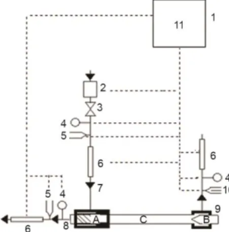
The schematic diagram of experi-mental set-up of RHVT was given in fig. 1. The compressed air was stored in a pres-sure tank – 2 with a capacity of 0.3 m3. The volumetric rate of the flow was adjusted by means of a spherical valve – 3. The com-pressed and adjusted air enters to the heli-cal vortex generator – A and exits as a swirling flow from RHVT body – C. Then, this swirling shape of flow is separated into hot and cold streams in RHVT body by means of the control valve – B.
Figure 1. The schematic of the experimental set-up of RHVT
The pressure and volumetric rate of the cold and inlet streams were measured by a relative pressure transmitter – 4 and an air flowmeter – 6. The volumetric rate of the hot side was calculated using the conservation law of mass. The temperature of the cold stream and compressed inlet air were measured by a PT100 type of thermocouple – 5. The temperature of the hot stream was measured by a relative humidity and temperature transmitter – 10. All the measured data were stored in a data logger – 11. The technical properties of the measurement devices were given in tab. 1 [22-24]. The uncertainties of the measurements were given in tab. 1. According to the findings of the uncertainty analysis, it was determined that the obtained results of the measurements were acceptable for the use in the design of the RHVTC.
Table 1. Technical properties and uncertainties of the measurement devices [22-24]
Device Type Property Sensibility Uncertainty Thermocouple, T6 Testo, PT 100 223.15- 573.15 K ±0.05 K ±0.264 K
Thermocouple, T8 Testo, PT 100 223.15- 573.15 K ±0.05 K ±0.445 K
Relative pressure
transmitter, P8 WİKA S-10 0-1000 kPa ±0.5% kPa ±5.68 kPa
Flowmeter (cold exit) Testo 6441 0.25-75 m3/h ±3% m3/h ±0.218 m3/h Flowmeter (inlet stream) Testo 6442 0.75-225 m3/h ±0.3% m3/h ±0.303 m3/h
Relative humidity and temperature transmitter T9, ϕ9 Testo 6881 233.15-453.15 K 0-100%R H ±0.2 K ±1% RH ±0.490 K ±0.154 RH Data logger Elimko PR-100 12 channel, 85-265 VAC – –
Designing of RHVTC system
The RHVT mainly consists of three components named as the helical vortex generator, control valve and RHVT body, see fig. 2. The used geometrical parameters of RHVT were chosen as height, e, width, w, of the channel, inner diameter, d, of the helical vortex generators and length, L, di-ameter, D, of RHVT bodies. All the helical vortex generators have a single nozzle and three different control valve angles were used (α = 30°, 45°, 60°). The technical properties of RHVT used in experiments were given in tab. 2.
The designed RHVTC system mainly forms of six components namely: evapora-tor – eva, compressor – C, condenser – con, heat exchanger – HE, throttling valve – tv, and RHVT. The schematic of RHVTC system was shown in fig. 3.
The refrigerant enters to the
com-Figure 2. The helical vortex generator (a), control valve (b), and RHVT body (c)
Figure 3. The schematic flow diagram of RHVTC system
pressor at point 1 and compressed refrigerant inlets to the condenser at point 2. The con-densed refrigerant enters to the heat exchanger at point 3 and transfers its heat to the cold stream of RHVT. At this time, the cold stream of the RHVT inlets to the heat exchanger at point 6, and leaves the heat exchanger at point 7 taking the heat of refrigerant. Then, the re-frigerant leaves the heat exchanger at point 4a for an expansion operation in the throttling valve – 5. During this process, the compressed air enters to the RHVT (8) and splits two streams namely: the cold – 6 and hot ones – 9.
Table 2. Technical properties of RHVT
Property e [mm] w [mm] h/w d [mm] D [mm] L [mm] d/D D [mm] L/D α [°] Vortex generator 0 2.0 4.5 0.44 6.15 12 – – – – A 3.3 – – – – B 5.1 – – – – C 6.0 – – – – D 7.1 – – – – M 1.5 6.0 0.25 3.3 – – – – N 5.1 – – – – O 5.7 – – – – J 7.1 – – – – RHVT body 1 – – – – 480 12 40 – 2 – – – – 350 29.17 – 3 – – – – 210 17.5 –
The VCC systems were designed for different compressor discharge pressure and suitable evaporator temperatures of cooling tomatoes, T1. The compressor outlet pressure was chosen between 1300 kPa to 2000 kPa. The pressure of the inlet stream of RHVT was changed between 201.325 kPa and 601.325 kPa. The ambient temperature was considered as 306.15 K for summer period (5 months) and 289.15 K for winter period (7 months). In exper-iments, the control valve opening position was adjusted 5 different fixed position. In the study, four different refrigerants chosen according to availabilities of the cycle parameter were performed. The thermodynamic properties of refrigerants are determined using a pack-age software called as REFPROP [29]. The parameters for designing of RHVTC handled in the study were given in tab. 3.
Table 3. The design parameters for RHVTC system
Evaporator temperature, T1 275.15-276.15-277.15 K Refrigerants R-134a, R143a, R404a, R507a Inlet air pressure of the vortex tube, P8 201.325-601.325 kPa
Energy and exergy analysis
The energy analysis, essentially the first law of thermodynamics, enables to deter-mine the amount of energy transportation and COP. However, the determination of the irre-versibility of a system is not possible with only the energy analysis. Exergy analysis gives more significant assessments by specifying the association of irreversibility or exergy destruc-tion of the refrigeradestruc-tion cycle components. In this study, the following assumpdestruc-tions were han-dled in the energy and exergy analysis:
– steady-state conditions were taken into account for all the components, – pressure losses in the pipelines were neglected,
– potential and kinetic energy effects were neglected,
– the compressor has an electrical, ηe, and mechanical, ηmec, efficiency of 90%, – the compressor has an isentropic efficiency of 70%,
– the heat exchanger has an efficiency of 70%, and – the reference state is 101.325 kPa and 293.15 K.
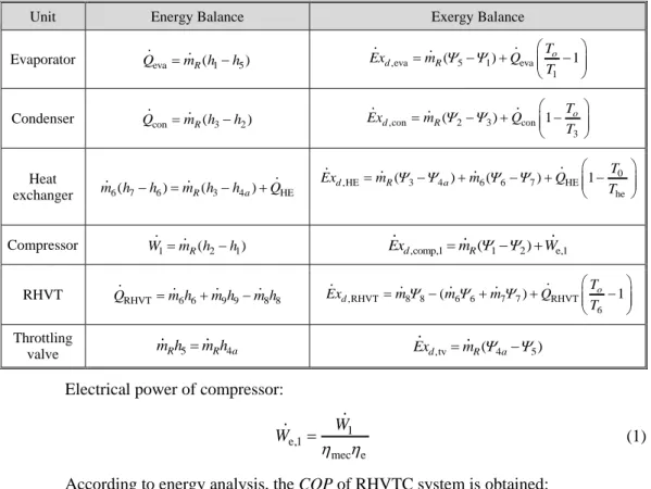
Under these assumptions, the governing energy and exergy equations of the RHVTC were obtained. Energy equations of the RHVTC system components were given in tab. 4.
Table 4. Energy and exergy balance of RHVTC system
Unit Energy Balance Exergy Balance Evaporator Qevam hR(1h5) ,eva 5 1 eva
1 ( ) o 1 R d T m Ex Q T Condenser QconmR(h3h2) ,con 2 3 con
3 ) 1 ( o d R T m x T E Q Heat exchanger m h6( 7h6)mR(h3h4a)QHE 0 ,HE 3 4 6 6 7 HE he ( ) ( ) 1 d R a T m m Q T Ex
Compressor W1mR(h2h1) Exd,comp,1mR( 1 2)We,1
RHVT QRHVTm h6 6m h9 9m h8 8 ,RHVT 8 8 6 6 7 7 RHVT 6 ( ) o 1 d T m m m Q Ex T Throttling valve m hR 5m hR 4a Exd,tvmR(4a5)
Electrical power of compressor:
1 e,1 mec e W W (1)
According to energy analysis, the COP of RHVTC system is obtained:
eva 9 9 7 7 RHVTC e,1 e,2 8 8 RHVT HE COP Q m h m h W W m h Q Q (2)
The COP of VCC system: eva VCC e,1 Q COP W (3)
Exergetic efficiency of RHVTC system, εRHVTC:
,eva ,con ,HE ,comp,1 ,RHVT ,tv ,comp,2
1 0 8 8 e,1 RHVT HE e,2 6 HE 1 1 1 d d d d d d d o Ex Ex Ex Ex Ex Ex Ex T T m W Q Q W T T (4)
Exergetic efficiency of VCC system, εVCC:
,eva ,con ,comp,1 ,tv
VCC e,1 1 Exd E d xd d W x E Ex (5) Economic analysis
The LCC, Csystem, of RHVTC system, eq. (6), occurs by the investment costs, Cic, salvage cost, Csc, operating costs, Coc, maintenance costs, Cmc, and benefit, Cb:
Csystem = Cic + Csc + Cmc + Coc – Cb (6) Investment costs, Cic:
Cic = CRHVT + CVCC + Che + Ccab (7)
where CRHVT [€] is the cost of Ranque-Hilsch vortex tube, Che [€] – the cost of heat exchang-er, Ccab [€] – the cost of cooling cabinet, CRHVT,comp [€] – the cost of RHVT compressor, and these devices costs are given in tab. 5 and cost values are constant.
Table 5. The devices and unit costs [23, 30]
Device Cost [€]
Ranque-Hilsch vortex tube 80
Heat exchanger 433.33
Cooling cabinet 1200
Cost of cooling system, CVCC, is calculated by [31]: VCC (253.99 eva 2061.3)
C Q (8)
The salvage cost of RHVTC system, was taken as 10% of the investment cost [32, 33]:
Csc = Cic 0.10 (9)
The maintenance cost of RHVTC system, was taken as 2% of the investment cost of the RHVTVCC system [32, 33]:
The benefit of RHVTC system, includes cooling earning: b ( cp,33 333600 cp,16 163600)0.0047
C m t m t (11)
where t33 [hours] is the summer period, t16 [hours] – the winter period, ṁcp,33 [kgs–1] – the cooled product summer period, and ṁcp,16 [kgs–1] – the cooled product winter period. The unit price of cooled product is 0.0047 € per kg [23]. Operating costs of the system are:
Coc = Ce (12)
where Ce is the electrical costs of RHVTC system. Electrical costs are: e [( e,1(33) 333600) ( e,1(16) 163600)]0.107
C W t W t (13)
where 0.107 € per kW is the electrical energy [34]. The net cash flow is:
CT = (Cb – Ce – Cmc)(1 + i)t–1 (14) where i is the interest rate, and t – the related year time of cash flow. The net present value (NPV) of RHVTC system is: ol T sc ic 0(1 ) ( ) t t C NPV C C j
(15)where ol is the lifetime of RHVTC system, and j – the discount rate. In this study, the lifetime of RHVTC system was added to calculations as 20 years. The discount and interest rates were taken as 9% and 7.25%, respectively [35, 36].
Results and discussion
The change in COP, exergy efficiency and NPV according to parameters discussed in each chart within the other RHVT parameters and operating conditions indicates the same trend. So the most effective parameters graphs are used in the study according to analyzes. The RHVT designs with the temperature differences of cold stream and inlet stream of RHVT of lower than 5 K were used in the RHVTC system. For this reason, some parameters had limited in these graphs.
Handling the operating parameters as R-134a, T1,a = 306.15 K, T1 = 276.15 K,
P2 = 1300 kPa, RHVT generator type of J, α = 45°, 3rd control valve opening position, the var-iation of COP of the RHVTC system vs. inlet air pressure of RHVT and RHVT body was ob-tained as seen in fig. 4.
As seen in fig. 4, COP values of RHVTC system increase by the increase of the L/D and the decrease of the inlet stream pressure of RHVT, P8. The COP of proposed RHVTC sys-tem ranges between 0.021 and 0.308. The changing of the COP values of RHVTC syssys-tem for R-134a, T1,a = 306.15 K, T1 = 276.15 K, P2 = 1300 kPa, RHVT generator J-type,
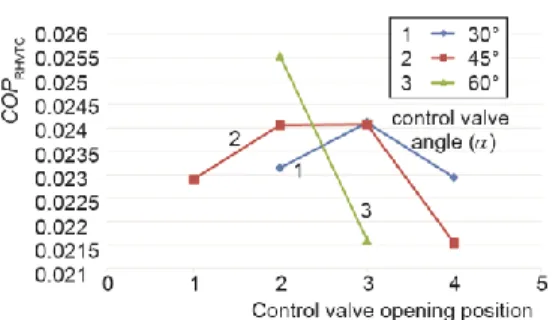
P8 = 601.325 kPa, 2nd RHVT body, according to different control valve angle, α, and control valve opening position are given in fig. 5.
As seen in fig. 5, the highest COP value of RHVTC system was obtained as 0.0255 for 60° control valve angel and 2nd control valve opening position. The COP of proposed RHVTC system ranges between 0.0316 and 0.0632. The changing of the COP values of RHVTC system for R-134a, T1,a = 306.15 K, J-type RHVT generator, P8 = 601.325 kPa, 1st RHVT body, α = 45°, 3rd control valve position according to different RHVT generator are given in fig. 6.
Figure 4. The variation of COPRHVTC vs. P8
and RHVT body; T1,a = 306.15 K, T1 = 276.15 K,
J-type RHVT generator, α = 45°, P2 = 1300 kPa,
3rd control valve position, R-134a
Figure 5. The variation of COPRHVTC vs. control
valve angle and control valve opening position;
T1,a = 306.15 K, T1 = 276.15 K, JRHVT-type
generator, P8 = 601.325 kPa, P2 = 1300 kPa,
2nd RHVT body, R-134a
According to fig. 6, COP of the RHVTC system increase with the increasing evapo-rator temperature and decreasing the compressor outlet pressure of the refrigerant. The COP of the RHVTC system range between 0.236 and 0.310. The changing of COP values of RHVTC system for T1,a = 306.15 K, T1 = 276.15 K, P2 = 2000 kPa, P8 = 501.325 kPa, 0-type RHVT generator, 1st RHVT body, α = 45°, 3rd control valve position according to cycle con-figurations and refrigerants are given in fig. 7.
Figure 6. The variation of COPRHVTC vs. P2
and T1; T1,a = 306.15 K, J-type RHVT generator,
P8 = 201.325 kPa, 2nd RHVT body,
3rd control valve position, R-134a
Figure 7. The variation of COP vs. refrigerant and system configurations; T1,a = 306.15 K,
0-type RHVT generator, P8 = 501.325 kPa,
P2 = 2000 kPa, T1 276.5 K, 3rd control valve
position, α = 45°, 1st RHVT body
As seen in fig. 7, the highest COP value was obtained as 2.750 for VCC system while using the R-507a as a refrigerant and the best value of COP was obtained as 0.0304 with using R-143 as a refrigerant in the RHVTC system. The changing of the exergy efficien-cy values of RHVTC, εRHVTC, system for R-143a, T1,a = 306.15 K, T1 = 276.15 K,
P2 = 1300 kPa, RHVT generator type of J, α = 45°, 3rd control valve position according to dif-ferent RHVT generator are given in fig. 8.
As seen in fig. 8, the exergy efficiency values of the RHVTC system increase by the decrease of the inlet stream pressure of RHVT, P8, for L/D of 40, 17.5. The exergy efficiency of proposed RHVTC system ranges between 0.0044 and 0.0309. The changing of the exergy efficiency values of RHVTC system for R-134a, T1,a = 306.15 K, T1 = 276.15 K,
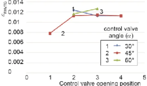
P2 = 1300 kPa, RHVT generator J-type, P8 = 601.325 kPa, 2nd RHVT body, according to dif-ferent control valve angle, α, and control valve opening position are given in fig. 9.
Figure 8. The variation of 𝜺RHVTC vs. P8 and
RHVT body; T1,a = 306.15 K, T1 = 276.15 K,
J-type RHVT generator, α = 45°, P2 = 1300 kPa,
3rd control valve position R-134a
Figure 9. The variation of εRHVTC vs. control
valve angle and control valve opening position;
T1,a = 306.15 K, T1 = 276.15 K, J-type RHVT
generator, P8 = 601.325 kPa, P2 = 1300 kPa,
2nd RHVT body, R-134a
According to fig. 9, the highest exergy efficiency value of RHVTC system was ob-tained as 0.0126 for 60° control valve angel and 3rd control valve opening position. The exer-gy efficiency of proposed RHVTC system ranges between 0.0078 and 0.0126. The changing of the exergy efficiency values of RHVTC system for R-134a, T1,a = 306.15 K, J-type RHVT generator, P8 = 601.325 kPa, 1st RHVT body, α = 45°, 3rd control valve position according to different RHVT generator are given in fig. 10.
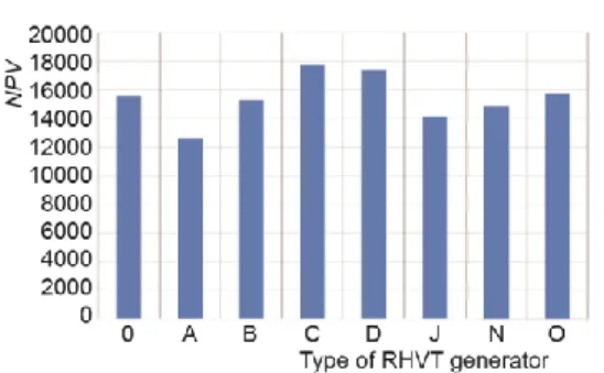
According to fig. 10, the exergy efficiency of the RHVTC system increase with in-creasing the evaporator temperature and the compressor outlet pressure of the refrigerant. The exergy efficiency of RHVTC system ranges between 0.027 and 0.092. The highest exergy ef-ficiency value was obtained as 0.2191 for VCC system while using the R-507a as a refriger-ant. The NPV of the RHVTC system increase with increasing the evaporator temperature and decreasing compressor outlet pressure of the refrigerant. The changing of the NPV of RHVTC system for R-134a, T1,a = 306.15 K, T1 = 276.15 K, P2 = 1300 kPa, P8 = 601.325 kPa, 1st RHVT body, α = 30°, 3rd control valve position according to different RHVT generators are given in fig. 11.
As seen in fig. 11, the highest NPV 17745 € of RHVTC system was obtained for C-type RHVT generator. The NPV of proposed RHVTC system ranges between 12601 € and 17745 €. The changing of the NPV of RHVTC system for R-134a, T1,a = 306.15 K, J-type RHVT generator, P8 = 601.325 kPa, 1st RHVT body, α = 45°, 3rd control valve position ac-cording to different RHVT generator are given in fig. 12.
According to fig. 12, NPV of the RHVTC system increase with increasing the evap-orator temperature and decreasing compressor outlet pressure of the refrigerant. The NPV of the RHVTC system ranges between 4229 € and 9587 €. The changing of the NPV values of RHVTC system for T1,a = 306.15 K, T1 = 276.15 K, P2 = 2000 kPa, P8 = 501.325 kPa, 0 type RHVT generator, 1st RHVT body, α = 45°, 3rd control valve position according to cycle con-figurations and refrigerants are given in fig. 13.
As seen in fig. 13, the highest NPV value was obtained as 11282 € for RHVTC sys-tem while using the R-143a as a refrigerant and for the same syssys-tem NPV value of VCC was obtained as 8756 €.
Figure 10. The variation of εRHVTC vs. P2 and
T1; T1,a = 306.15 K, J-type RHVT generator,
P8 = 201.325 kPa, 2nd RHVT body,
3rd control valve position, R-134a
Figure 11. The variation of NPV vs. RHVT generator; T1,a = 306.15 K, T1 = 276.15 K,
P8 = 501.325 kPa, P2 = 1300 kPa, 1st RHVT body,
α = 30°, 3rd control valve position, R-134a
Figure 12. The variation of NPV vs. P2 and T1;
T1,a = 306.15 K, J-type RHVT generator, P8 =
201.325 kPa, 2nd RHVT body, 3rd control valve
position, R-134a
Figure 13. The variation of NPV vs. refrigerant and system configurations; T1,a = 306.15 K,
0-type RHVT generator, P8 = 501.325 kPa,
P2 = 2000 kPa, T1 = 276.15 K, 3rd control valve
position, α = 45°, 1st RHVT body
The COP of the RHVTC system increase with evaporator temperature and decreas-ing inlet stream pressure. Accorddecreas-ing to the energy analysis results, the most effective RHVT body, refrigerant, helical vortex generator, control valve angle and control valve opening posi-tion are 1st, R-134a, J-type, 45° and 3rd, respectively. The maximum COP of RHVTC system was determined as 0.310 and 0.0.317 for the summer and winter mode, respectively. These system properties were J-type type generator, 1st RHVT body, control valve angle of 45°,3rd control valve opening position, R-134a, T1 of 277.15 K, P2 of 1300 kPa and P8 of
201.325 kPa. Exergy efficiency of this system was 0.0348 and 0.0384 for the summer mode and winter mode, respectively. The NPV of this RHVTC system was calculated as 9587 €. For the same operating conditions, COP of the VCC system was calculated as 2.6346. The NPV of the VCC was increased by integrating the vortex into the system. However, the ener-gy and exerener-gy efficiencies of the system were declining. The highest exerener-gy efficiency of the RHVTC system was calculated as 0.0976 for winter period in which the helical vortex genera-tor of J-type, 1st RHVT body, control valve angle of 45°, 4th control valve opening position and R-134a were used and operating conditions of this system was T1 of 277.15 K, P2 of
2000 kPa and P8 of 201.325 kPa. The COP and NPV of this system were determined as
Conclusion
In this study, the performance of vapor compression cooling system integrated with RHVT was investigated. For this purpose, the geometrical parameters, the pressure of inlet flow of RHVT and the cold mass fraction were taken into account. Additionally, nine different the helical vortex generators, three different control valve angles and three differ-ent RHVT bodies were also taken into consideration. In this regard, a number of 355040 de-signs was formed and analyzed by energy, exergy and economic analysis. The exergy effi-ciency and NPV of the RHVTC system are increasing with increasing RHVT body length, evaporator temperature and decreasing the inlet stream pressure. The exergy efficiency and NPV of the RHVTC system increasing with a decrease of the compressor outlet pressure of the refrigerant. The main reason for the decreasing energy and exergy efficiencies of the RHVTC according to the VCC system is the hot outlet stream of RHVT has not been used in this system. The cooling and drying have been extended the shelf life of the foods. In this sense, a hybrid system using the both cooling and drying process at the same time will be an efficient evaluation.
Acknowledgment
This study was supported by Scientific Research Projects Unit of Dumlupinar Uni-versity (DPUBAP) under grant of the project no of 2013/5.
Nomenclature C – cost, [€] Ex – exergy, [kW] h – specific enthalpy, [kJkg–1] ṁ – mass-flow, [kJs–1] n – number of measurements P – pressure, [kPa]
ol – operating life, [year]
R – air gas constant, [kJkg–1K–1]
Q – heat energy, [kJs–1] r – discount rate, [%] SD – standard deviation T – temperature, [K] t – time, [year] U – uncertainty W – electrical power, [kJs–1] Greek symbols ε – exergy efficiency, [%] ψ – specific exergy, [kJkg–1] he – electrical efficiency
hmec – mechanical efficiency
References
[1] Unal, F., Ozkan, D. B., An Application of Exergo-Economic Analysis for Power Plants, Thermal
Sci-ence Journal, 22 (2018), 6A, pp. 2653-2666
[2] Ranque, G. J., Experiences sur la detente giratoire avec production simulanees ’un echappement d’air chaud et d’air froid, (in French), Journal de Physique et Le Radium, 7, (1933), 112-114
[3] Saidi, M. H., Valipour, M. S., Experimental Modeling of Vortex Tube Refrigerator, Applied Thermal
Engineering, 23 (2003), 15, pp. 1971-1980
[4] Pourmahmoud, N., et al., Numerical Analysis of the Effect of Helical Nozzles Gap on the Cooling Ca-pacity of Ranque-Hilsch Vortex Tube, International Journal of Refrigeration, 35 (2012), 5, pp. 1473-1483
[5] Dutta, T., et al., Numerical İnvestigation of Gas Species and Energy Separation in the Ranque-Hilsch Vortex Tube using Real Gas Model, International Journal of Refrigeration, 34 (2011), 8, pp. 2118-2128 [6] Chang, K., et al., Experimental İnvestigation of Vortex Tube Refrigerator with a Divergent Hot Tube,
International Journal of Refrigeration, 34 (2011), 1, pp. 322-327
[7] Xue, Y., et al., Visualization of the Flow Structure in a Vortex Tube, Experimental Thermal and Fluid
Science, 35 (2011), 8, pp. 1514-1521
[8] Rahbar, N., et al., Numerical İnvestigation on Flow Behavior and Energy Separation ın a Micro Scale Vortex Tube, Thermal Science, 19 (2015), 2, pp. 619-630
[9] Xue, Y., et al., Energy Analysis Within a Vortex Tube, Experimental Thermal and Fluid Science, 52 (2014), Jan., pp. 139-145
[10] Kirmaci, V., Exergy Analysis and Performance of a Counter Flow Ranque-Hilsch Vortex Tube Having Various Nozzle Numbers at Different inlet Pressures of Oxygen and Air, International Journal of
Re-frigeration, 32 (2009), 7, pp. 1626-1633
[11] Cebeci, I., et al., The Effects of Orifice Nozzle Number and Nozzle Made of Polyamide Plastic and Aluminum with Different Inlet Pressures on Heating and Cooling Performance of Counter Flow Ranque-Hilsch Vortex Tubes: An Experimental Investigation, International Journal of Refrigeration, On-line first, http://dx.doi.org/doi:10.1016/j.ijrefrig.2016.07.013, 2016
[12] Dincer, K., et al., Modeling of the Effects of Length to Diameter Ratio and Nozzle Number on the Per-formance of Counterflow Ranque-Hilsch Vortex Tubes using Artificial Neural Networks, Applied
Ther-mal Engineering, 28 (2008), 17-18, pp. 2380-239
[13] Dincer, K., et al., Modeling of the Effects of Plug Tip Angle on the Performance of Counter-Flow Ranque-Hilsch Vortex Tubes using Artificial Neural Networks, Journal of Thermal Science and
Tech-nology, 28 (2008), 2, pp. 1-7
[14] Aydin, O., Baki, M., An Experimental Study on the Design Parameters of a Counter-Flow Vortex Tube,
Energy, 31 (2006), 14, pp. 2763-2772
[15] Markal, B., et al., An Experimental Study on the Effect of the Valve Angle of Counter-Flow Ranque-Hilsch Vortex Tubes on Thermal Energy Separation, Experimental Thermal and Fluid Science, 34 (2010), 7, pp. 966-971
[16] Pouraria, H., Zangooee, M. R., Numerical İnvestigation of Vortex Tube Refrigerator with a Divergent Hot Tube, Energy Procedia, 14 (2012), Dec., pp. 1554-1559
[17] Shamsoddini, R., Khorasani, A. F., A New Approach to Study and Optimize Cooling Performance of a Ranque-Hilsch Vortex Tube, International Journal of Refrigeration, 35 (2012), 8, pp. 2339-2348 [18] Berber, A., et al., Rule-Based Mamdani-Type Fuzzy Modeling of Heating and Cooling Performances of
Counter-Flow Ranque-Hilsch Vortex Tubes with Different Geometric Construction for Steel, Energy, 51 (2013), Mar., pp. 297-304
[19] Avci, M., The Effects of Nozzle Aspect Ratio and Nozzle Number on the Performance of the Ranque-Hilsch Vortex Tube, Applied Thermal Engineering, 50 ( 2013), 1, pp. 302-308
[20] Acar, S. M., Arslan, O., The Effect of Cold Stream of Vortex Tube on Efficiency of the Vapor Compres-sion Refrigeration System, Proceedings, International Conference on Computational and Experimental Science and Engineering (ICCESEN-2014), Antalya, Turkey, 2014
[21] Acar, S. M., et al., Thermodynamic Analysis of Ranque-Hilsch Vortex Tube Aided Hybrid Cooling and Drying System, Proceedings, 11th Sustainable Development of Energy, Water and Environment Sys-tems, Lisboa-Portugal, 2016
[22] Acar, S. M., Arslan, O., Exergo-Economic Evaluation of a New Drying System Boosted by Ranque-Hilsch Vortex Tube, Applied Thermal Engineering, 124 (2017), Sep., pp. 1-16
[23] Acar, S. M., Thermodynamic Evaluation and Design of Ranque-Hilsch Vortex Tube Aided Hybrid Cool-ing and DryCool-ing System, (in Turkish), Ph. D. thesis, Dumlupinar University, Institute of Applied Scienc-es, Kutahya, Turkey, 2016
[24] Acar, S. M., Arslan, O., Performance Analysis of a New Hybrid Cooling - Drying System,
Environmen-tal Progress & Sustainable Energy, 23 (2018), 5, pp. 1808-1828
[25] Hooper, F. C., Ambrose, C. W., An Improved Expansion Process for the Vapour Refrigeration Cycle,
Proceedings, 4th Canadian Congr. Applied Mechanics, Montreal, Canada, 811-812, 1973
[26] Collins, R. L., Lovelace, R. B., Experimental Study of Two-Phase Propane Expanded through the Ranque-Hilsch Tube, ASME Journal Heat Transfer, 101 (1979), 2, pp. 300-305
[27] Nellis, G. F., Klein, S. A., The Application of Vortex Tubes to Refrigeration Cycles, Proceedings, Inter-national Refrigeration and Air Conditioning Conference, Purdue University, West Lafayette, Ind., USA, 2002, pp. 537
[28] Sarkar, J., Exergy Analysis of Vortex Tube Expansion Vapor Compression Refrigeration System,
Inter-national Journal of Exergy, 13 (2013), 4, pp. 431-446
[29] ***, REFPROP., NIST Reference Fluid Thermodynamic and Transport Properties. NIST Reference Da-tabase. Version 9.0, National Insitiute of Standards and Technology U.S.A., 2010
[30] Yilmaz, E. A., Price Proposal for Ranque-Hilsch Vortex Tube Supported Cooling System, TESTTEKNIK, Konak, Turkey, 2015
[31] ***, CSB (T. C. Cevre ve Sehircilik Bakanlıgı), Republic of Turkey Ministry of Environment and Ur-banization, http://www.csb.gov.tr, Unit price of cooling unit used in system, (Last access: September 2015)
[32] Guler, T., Yucedag, M., Feasibility Report of Atmosphere Controlled Cold Storage Facility, Internal Re-port, Direct Business Support Program, Fırat Development Agency (in Turkish), 2011, Firat, Turkey, http://fka.gov.tr/SayfaDownload/SOGUK_HAVA.pdf
[33] Yogunlu, A., et al., The Analysis And Pre-Feasibility of Frozen Fruit And Vegetable Sector, (in Turkish), Internal Report, Fırat Development Agency (in Turkish), 2013, Firat, Turkey, http://fka.gov.tr/Content Download/Dondurulmus_Meyve_Sebze_Sektor_Analizi_ve_On_Fizibilitesi.pdf
[34] ***, EMRA, June 29, Energy Market Regulatory Authority board decision, (in Turkish), Decision No: 5666, Official Gazette of Turkish Republic No. 29401, 2015
[35] ***, CBRT (Central Bank of Republic of Turkish), 2015a, Interest rate, http://www.tcmb.gov.tr/ wps/wcm/connect/tcmb+tr/tcmb+tr/main+menu/duyurular/basin/2015/duy2015-13, (Last access: Sep-tember 2015)
[36] ***, CBRT (Central Bank of Republic of Turkish), Discount rate, 2015b, http://www.tcmb.gov.tr /wps/wcm/connect/tcmb+tr/tcmb+tr/main+menu/para+politikasi/reeskont+ve+avans+faiz+oranlari, (Last access: September 2015)
Paper submitted: September 19, 2017 © 2019 Society of Thermal Engineers of Serbia. Paper revised: November 20, 2017 Published by the Vinča Institute of Nuclear Sciences, Belgrade, Serbia. Paper accepted: November 28, 2017 This is an open access article distributed under the CC BY-NC-ND 4.0 terms and conditions.
![Table 1. Technical properties and uncertainties of the measurement devices [22-24]](https://thumb-eu.123doks.com/thumbv2/9libnet/4010518.55116/3.893.146.750.456.697/table-technical-properties-uncertainties-measurement-devices.webp)

![Table 5. The devices and unit costs [23, 30]](https://thumb-eu.123doks.com/thumbv2/9libnet/4010518.55116/6.893.204.746.280.546/table-devices-unit-costs.webp)