i rT'/'-tlyV Â'Ÿ ш \ ы т А г т н r / ç
66S0 5
1.000 ù ^ T Ы ■ Í H E N i . ? f t , i J [ 1 t. V ; î Й Ci H ? K: Ъ EN< Í ^ N t E R ■[ N i , ' . f g ^ ; Ê\f^i·Β.|ΐ n-ÆNT У ^ i r V f r l ΐ Ç
/ ? ?'■ i «*- ■:'?-SEMI-AUTOMATIC VIDEO OBJECT SEGMENTATION
A THESIS
SUBMITTED TO THE DEPARTMENT OF ELECTRICAL AND ELECTRONICS ENGINEERING
AND THE INSTITUTE OF ENGINEERING AND SCIENCES OF BILKENT UNIVERSITY
IN PARTIAL FULFILLMENT OF THE REQUIREMENTS FOR THE DEGREE OF
MASTER OF SCIENCE
By
Ersin Esen
September 2000
^¿ΖΟ.ς-¿ O O O
I certify that I have read this thesis and that in rny opinion it is fully adecinate, in scope and in quality, as a the.sis for the degree of Master of Science.
Prof. Dr. Levent Onural (Supervisor)
I certify that I have read this thesis and that in my opinion it is fully adequate, in scope and in quality, as a thesis for the degree of Master of Science.
)v ^
Assoc. Prof. Dr. Gözde Bozdağı
I certify that I have read this thesis and that in my opinion it is fvdly a.dequate, in scope and in quality, as a thesis for the degree of Master of Science.
Assoc. Prof. Dr. Orhan Arikan
ABSTRACT
SEMI-AUTOMATIC VIDEO OBJECT SEGMENTATION
Ersin Esen
M. S. in Electrical and Electronics Engineering
Supervisor: Prof. Dr. Levent Onural
September 2000
Content-based iunetionalities form the core of the future multimedia applications. The new multimedia standard MPEG-4 provides a new form of interactivity with coded audio-visual data. The emerging standard MPEG-7 specifies a common description of various types of multimedia information to index the data for storage and retrieval. However, none of these standards specifies how to extract the content of the multimedia data. Video object segmentation addresses this task and tries to extract semantic objects from a scene. Two tyj)es of video object segmentation can be identified: unsupervised and supervised. In unsupervised méthods the user is not involved in any step of the process. In supervised methods the user is requested to supply additional information to increase the quality of the segmentation. The proposed weakly supervised still image segmentation asks the user to draw a scribble over what he defines as an object. These scribbles inititate the iterative method. .A.t each iteration the most similar regions are merged until the desired numljer of regions is reached. The proposed .segmentation method is inserted into the unsupervised COST211ter .A-ualysis Model (.A.M) for video object segmentation. The AM is modified to handh' the sujiervision. The new semi-automatic AM requires the user intei actimi for onl>· first frame of the video, then segmentation and object tracking is doin' automatically. The results indicate that the new semi-automatic AM constituK's a good tool for video oliject segmentation.
K('.ywords: Image segmentation, video object segmentation, su]K'rvised si'gmentation. unsiipervi.sed .segmentation, object tracking, MPEG-4, .MPEG-7.
ÖZET
YARI-OTOMATİK VİDEO NESNE BÖLÜTLEME
Ersin Esen
Elektrik ve Elektronik Mühendisliği Bölümü Yüksek Lisans
Tez yöneticisi: Prof. Dr. Levent Onural
Eylül 2000
İçerik-t.abaıılı işlevsellik gelecekteki multirnedya n3'gulamalarınm özünü oluşturmaktadır. Yeni ınultimedya standardı MPEG-4, kodlanmış multirnedya verileriyle etkileşimin j^eni düzenini belirlemektedir. Standartlaşma aşamasındaki MPEG-7 ise multimed.ya verilerine veritabanlari üzerinden ulaşmayı kolaylaştırmak için ortak bir multimed}'^a içerik tanımı belirlemektedir. Fakat, her iki standart da video verisindeki içeriğin nasıl bulunup çıkarılacağını tammlamamaktadır. Video nesne bölütlernenin hedefi bir video sahnesindeki anlamlı iK'sneleri Inılııp çıkarmaktır. Gözetimli ve gözetimsiz olmak üzere iki tür video nesne bölütleme tanımlanabilir. Gözetimsiz türde kullanıcı işleme hiçbir aşamada dahil olmamaktadır. Gözetimli türde ise kullanıcıdan işlemin kalitesini artırmak için (îk bilgi istenir. Bu çalişrnada önerilen göızetimli görüntü bölütlemesinde kullanıcı nesneler üzerinde çizgiler çizer. Bu çizgih'r jünelemeli yöntemin ilk aşamasında kullanılır. Her bir yinelemede (uı çok benzeven bölgciler birleşt.irilir. Yinelemeler istenen bölge sayısına ulaşılana d('k sürdürülür. COST211ter Analiz Modeli elden geçirilerek önerilen gözetimli bölütleme algortirmasını kullanabilecek duruma getirilmiştir. OrtaA’a çıkan yeni >'arı-otonıatik analiz modeli, yalnızca ilk video karesi için kullanıcıdan çizgi biçimindeki ek bilgiyi istc'inektedir. Elde edilen sonuçlar l)u yeni yönti'inin \-ideo nesne bölül.h'iiKî için iyi bir yöntem olduğunu kamtlamaktadır.
Anahtar Kdim dcr: Görüntü bölütleme, video nesne İHİlütleme. gözetimli bö)lütl(!iu('. gözi'tiınsiz bölütleme, nesne takibi, MPEG-4, MPEG-<.
ACKNOWLEDGMENTS
I would like t,o (express rny deepest gratitude to Prof. Dr. Leviuit Ouural for his supervision.
I would also like to thank the members of my committee, Assoc. Prof. Dr. Gözde Bozdağı and Assoc. Prof. Dr. Orhan Arikan for their comments on the thesis.
C ontents
1 Introduction 1
1.1 The Purpose of Video Object Segmentation 1
1.2 Outline of the T h e s is ... 6
2 V ideo Object Segm entation Problem 7
2.1 Major Steps of Video Object Segm entation... 7
2.2 What is an object? 8
2.3 Unsuperлdsed Video Object Segmentation 9
2.4 Supervised Video Object Segm entation... 11
2.5 The Information Source For Segmentation 14
2.6 The Requirements On Video Object Segmentation... 15
3 W eakly Supervised Still Image Segm entation 17
3.1 The Format of Supervision... 17 3.2 Weakly Supervised Segmentation M ethod... 18
3.3 Comiuitational Complexity of the Method 22
3.4 Riisults for Coloi· 23
3.5 R.esull.s for Motion 25
4 Bilkent Analysis M odel For Sem i-Autom atic Video Object
Segm entation 30
4.2 The Structure of the B A M ... .32
4.2.1 User I n p u t... 33
4.2.2 Adaptive Frame S k ip ... 33
4.2.3 Global Motion Estimation/Compensation 35 4.2.4 Scene Cut D e te c tio n ... 35
4.2.5 Supervised Color S eg m en tatio n ... 36
4.2.6 Color Segmentation... 36
4.2.7 Local Motion A n a ly sis... 38
4.2.8 Supervised Motion Segmentation 39 4.2.9 Motion Segmentation... 40
4.2.10 Local Motion C om pensation... 40
4.2.11 Change D etection... 41
4.2.12 Rule Processor 41 4.2.13 Post Processor ... 45
4.2.14 Object Tracking... 46
4.3 Sam]de Run of the B A M ... 47
5 R esults 50 5.1 Computational T i m e ... 53
6 Conclusion 68
A Bilkent A nalysis M odel Version 5 Software Description 75
В Test Specifications 83
List o f Figures
1.1 Tlie contents of a, video. .3
1.2 A scene from an MPEG-4 video... 4
1.3 MPEG-4 system for encoding and decoding visual objects. 5 1.4 The scope of MPEG-7... 5
2.1 Major steps of video object segmentation. 7 2.2 Tlie user clicks on the regions... 12
2.3 The initial mask is required... 12
2.4 The user draw scribbles on the objects... 13
2.5 The user marks iroints on the boundary of the object... 13
3.1 The format of scribbles. TS
3.2 The liidvs l)etw(ien two nodes. 20
3.3 A color segmentation result for Akiyo; (a) input image and supervision (b) segmentation mask (c) segmented object. 24 3.4 Anotlu'r color sc'gmentation result for Akiyo: (a) input image and
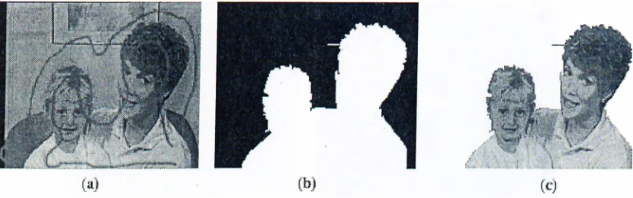
siqxn'vision (b) segmentation mask (c) segmented object. 24 3.5 -A color segmentation result for Mother & Daughter: (a) input
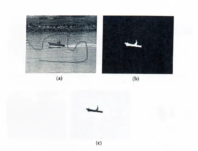
image and su]>ervision (1)) segmentation mask (c) segmented obji'ct. 25 3.G color si'gmentation result for Coastguard: (a) in[)ut image' and
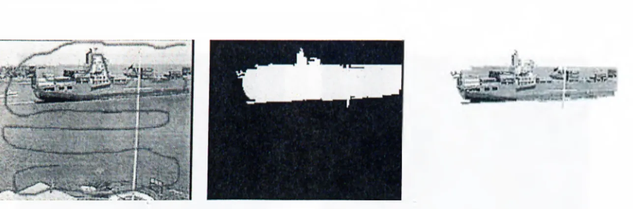
3.7 A color ,s(!girieiitafcion result for Container: (a) input image and .supervision (b) segmentation mask (c) segmented object. 27 3.8 A color segmentation result for Hall Monitor: (a) input image and
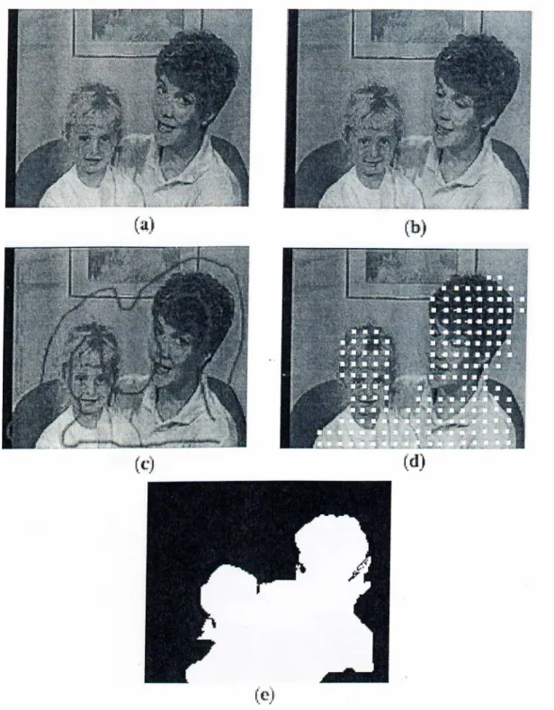
supeiaision (b) segmentation mask (c) segmented object... 27 3.9 A motion segmentation result for Mother&Daughter: (a) 0'·^' frame
(b) 25'^'· frame (c) supervision (d) motion vectors (e) segmentation mask... 28 3.10 A motion segmentation result for Table Tennis: (a) (У■'^ frame (1))
I '’'- frame (c) supervision (d) motion vectors (e) segmentation mask. 29 4.1 The Block Diagram of BAM Version 5... 31 4.2 A sani]ile supervised color segmentation from Akiyo sequence. 36 4.3 A sample color segmentation from Akijm sequence. 38 4.4 A sample supervised motion segmentation for Akijm sequence
using HBM... 40 4.5 A sami:)le motion segmentation for Akiyo sequence using HBM. . . 41
4.6 A sample CDM for Aki}m sequence. 42
4.7 An t:xample of mapping : (a) color regions (b) motion segmenta tion mask (c) mapping color regions onto motion segmentation (d)
corrected boundaries of motion segmentation. 44
4.8 Result of Mode 0 : (a) input frame and user input (b) result mask. 47 4.9 Result of Mode 1 : (a) color segmentation mask (b) motion
segmentation mask (c) change detection mask (d) motieni com-
])('nsat(Kl mask (e) result mask. 48
4.10 Result of Mode 2 : (a) color segmentation mask (b) motion segTtK'iital.ion mask (c) change detection mask (d) motion com-
])cnsat('d mask ((') lesult mask. 49
5.1 Resull. of i)revioiis uiisu])crvised version for Akiyo sequence... .54
5.2 .Л resiill of BAM for Akiyo sequence. 55
5.3 5.4 5.6 5.7 5.8 5.9 5.10 5.11 5.12 5.13 5.14
y\.uol;lier i(!sult of BAM for Akiyo sequence... 56 R,esull; of jrrevious unsupervised version for Mother&Da,ught,(u·
жчщепсе. 57
A result of BAM for Mother&Daughter sequence. 58 Result of previous unsupervisecl version for Container sequence. 59 A result of BAM for Container sequence... 60 Result of ])revious unsupervised version for Coastguard secjuence. 61 A result of BAM for Coastguard sequence... 62 Another result of BAM for Coastguard sequence. 63 Result of i)revious unsupervised version for Table Tennis sequence. 64 A result of BAM for Table Tennis sequence. 65 Result of i)revious unsupervised version for Hall Monitor s(!quence. 66 A result of BAM for Hall Monitor sequence. 67
List o f Tables
4.1 The ro.snll,s of Adaptwe Frame S k ip ... ,34
4.2 The ])arameters of H B M ... 38
4.3 The output of the rule processor in mode 1 ... 47
4.4 The output of the rule processor in mode 2 ... 49
4.5 The output of the object tracking module in mode 2 ... 49
5.1 Computation Tinu-is of Modes of BAM for Aki3^o Sequence . . . . 53
A.l Directory structure of BAM 7C A.2 Structure of the parameter file part 1 ... 77
A.3 Structure of the parameter file part 2 ... 78
A.4 Structure of the ])arameter file part 3 ... 79
A.5 Structure of the ijararneter file part 4 ... 80
A.C Struc.tuni of the ])arameter file part 5 ... 81
A.7 Structure of the i)arameter file part 6 ... 82
C hapter 1
Introdu ction
1.1
T h e P u r p o se o f V id eo O b ject S e g m e n ta tio n
The new digital age changed the life drasticallj^ Multimedia is one of the most affected ficdds. The demands of people are increasing as the digital technologies find a place in onr lives. Multimedia data should be compressed efficiently to minimize storage costs. The efficient compression is necessary also for the transmission of the mnltimedia data over the current network. Tlui mnltimedia data should be ¡processed to facilitate its reuse. It must l)e proti'cted against corruption. In soirui cases it should be encrypted. The protection of intcdh'ctual prop(!rty rights is an important issue that concerns multimedia data l)roadcasting and transmission. Furthermore, it is no more enough for a person to be a ])assive obseia’(',r of the multimedia data. In the new age the person ne(‘ds to interact with IIk' contiuit of the multimedia data for a variet>^ of purpos(!s such
as vid(!0 editing (that enabh'S modifying, improving or constructing a brand lu'w vid('o), e-comm('rc(i, and audio-visual database query and retrieval. In onha· to achieve these tasks tin' multinu'dia data must be in a conten(.-l)ased form so Ihal ir.s c.onti'iits can be maiii])ulated. The video object segmentation addi('sses iIk' accessing lh(' contents of a vid(io and aims at (extracting its contents.
The old mnltinieclia standards could no more serve for the new demands of the people!. The interaction of the user with the old standards was very limite'd. The user could perform hackward/forward traversing in a video in addition to pausing the video. If he desired to alter the contents of a video, he had to jrroceîss the video frame l)y frame. If the excessive number of frames is consider(!(l, it is obvious that this kind of ])rocessing is not an easy task. Furthermore, it is not a suitable c:hoice with respect to what the new digital age offers. The multiimidia. data must be i)resented in such a way that the requirements placed upon it anî met. This vital reciuirement and the inefficiencies of the old standards formed the basis of the new multimedia standard MPEG-4F The main goal of this new standard is to ju'ovide a new form of interactivity with coded audio-visual data [1].
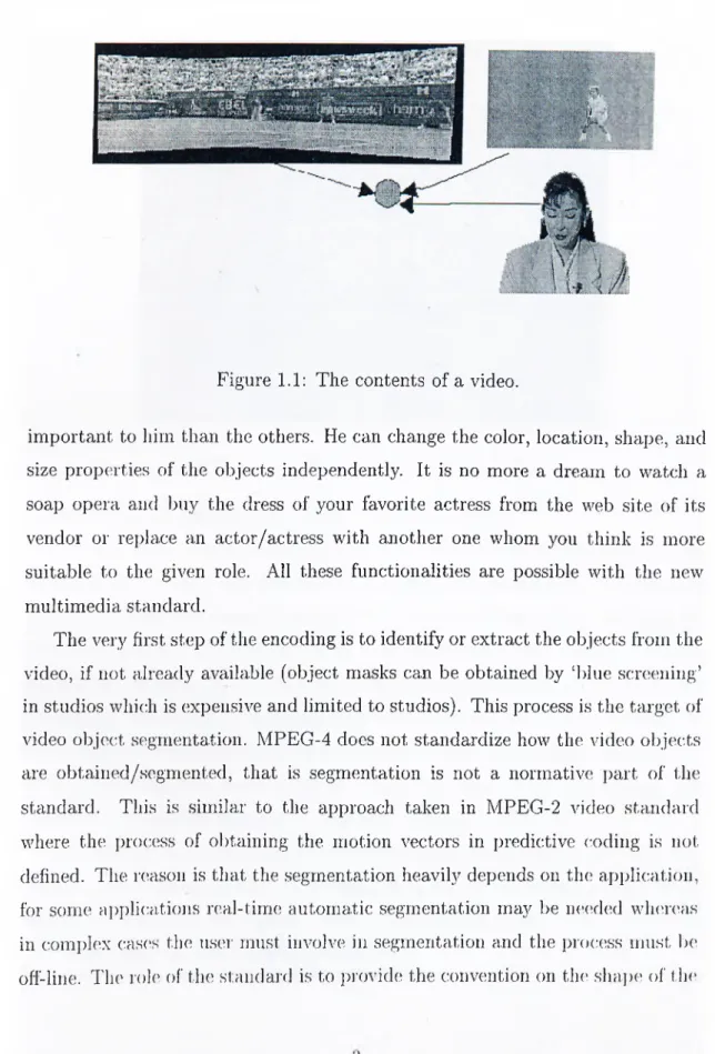
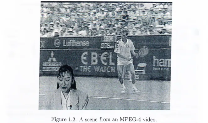
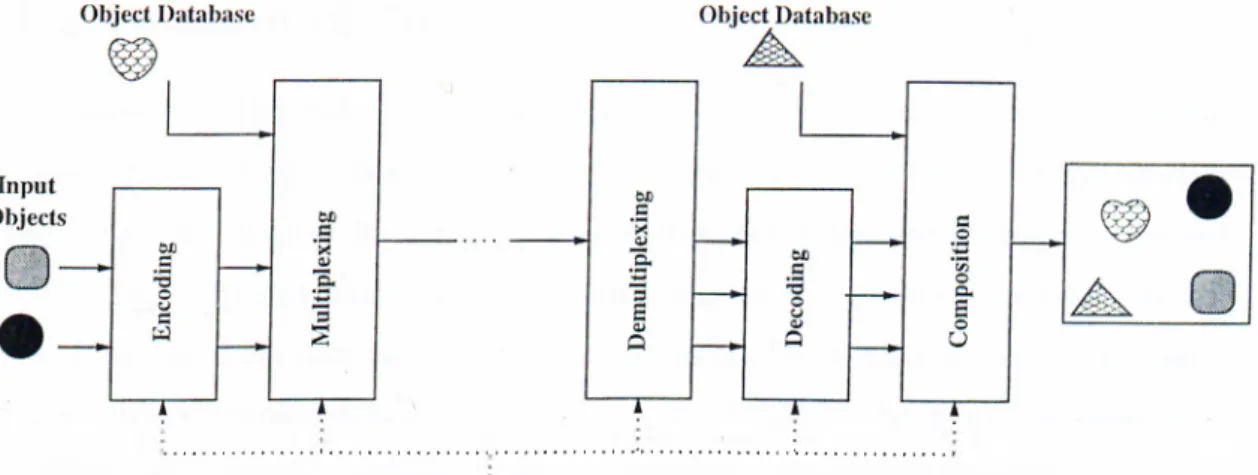
The MPEG-4 standard has a scene representation tha.t is composed of distinct audio-visual olqects that have arbitrary shapes representing the content of a video (a \-ideo object). Figure 1.2 shows, a sample composition of three different objects shown in Figure 1.1. Figure 1.3 shows a typical MPEG-4 video encoding and decoding systcun for visual objects. First, the input objects are encoded. Then another objiîct from an object database is added to the video. After the transmission, the video data is demultiplexed and objects are decoded. In the final ste]) com])osition is i)erformed with an additional object from an olqo'ct database. Th(! user can interact with the s}cstem in any step.
This new i(!p](!sentation enables MPEG-4 to support the content-) )as('d functionalities l)eyond comi)ression, storage and transmission consichuations. The audio-visual data, ('ncai)sulated as objects are encoded independently so that, t.lu'y can be manipulated indi^'idually. The user can replace the responsil)ilities ol' l lu' (hîcodcr ill ordi'r to alter the content of the video according to his will. He may want to ri'niOAC an obje.cf. from the scouie or add anothei· one. For a jiarl.icular object he may increase the spatial or temporal resolution since that oliji'ct is nioi’e
*The address of t lie oflieial website of MPEG-4 is lir.t))://www.c.se)t.it,/iiii)eg/.staiidards/in])eg-4/nii)eg-4.htm
Figure 1.1: The contents of a video.
important to him than the others. He can change the color, location, shape, and size properties of the objects independently. It is no more a dream to watch a soap opera and buy the dress of your favorite actress from the web site of its vendor or replace an actor/actress with another one whom you think is more suitable to the given role. All these functionalities are possible with the new multimedia standard.
The very first step of the encoding is to identify or extract the objects from the video, if not already available (object masks can be obtained by ‘blue screening’ in studios which is expensive and limited to studios). This process is the target of video object segmentation. MPEG-4 does not standardize how the video objects are obtained/segmented, that is segmentation is not a normative part of the standard. This is similar to the approach taken in MPEG-2 video standard where the jorocess of obtaining the motion vectors in predictive coding is not defined. The reason is that the segmentation heavily depends on the application, for some ai)plications real-time automatic segmentation may be needed whereas in complex cases the user must involve in segmentation and the [process must be off-line. The roh' of the standard is to provide the convention on the shaj)e of tlie
Figure 1.2: A scene from an MPEG-4 video. object so that all decoders can decode the video object.
Another important need for video object segmentation stems from audio visual database query and retrieval. This subject is addressed by the emerging standard MPEG-?“^, formally the Multimedia Content Description Interface [2]. The main goal of MPEG-7 is to specify a common description of various types of multimedia information so that a user can use this description to index the data for storage and retrieval. The scope of MPEG-7 is shown in Figure 1.4. MPEG-7 standardizes the description of the extracted features. This common description of various multimedia t\q)es (such as video clips, audio clip, still images, 3D models) will make the database search more efficient and flexible.
In MPEG-7, visual data can be described in many semantic levels tliat may coexist. In low abstraction level the visual data can be described in terms of its shape, size, and color information. At a higher level of abstraction the user can
"The addres.s of tlx; oflidal wc;b,sit(· of MPEG-7 is http://www.cselt.it/iii])eg/staudards/ni])eg-7/nii)eg-7.htm
User Interaction
Figure 1.3: MPEG-4 system for encoding and decoding visual objects.
Scope of MPEG-7
Figure 1.4: The scope of MPEG-7.
enter data specific information such as intellectual property rights, the recording time, place, and/or reason of the visual data. Similar to MPEG-4, MPEG-7 do('s not standardize the feature extraction. The video object segmentation constitutes a good tool to extract the low level features.
In the light of the new demands placed on the multimedia data and the new standards, the video object segmentation is a very important topic. It is a very hard problem (especially for generic video sequences for which there are no constraints) and there is still no exact solution. The research community works on this subject for a Iretter segmentation method. In this thesis, a solution to this problem is j)roi)Osed with the intention to meet the requirements of the new digital age.
1.2 O u tlin e o f th e T h esis
In Chapter 2, the video object segmentation problem is discussed and A^arious approaches to the problem are mentioned. The main contribution of this work is presented in Chapter 3. Chapter 3 describes the proposed weakly supervised still image segmentation algorithm. In Chapter 4, the new Analysis Model, which we call from now on as Bilkent Analysis h4odel (BAM), for semi-automatic video object segmentation is described. The BAM is the modified version of COST211ter Analj^sis Model Version 4 based on the segmentation algorithm presented in Chapter 3. In Chapter 5, the results of the new Analysis Model on various video sequences are given and compared to the results of the old version. Finally, Chapter 6 concludes the thesis with the remarks and future directions.
C hapter 2
V ideo O bject Segm entation
P rob lem
Video obJ(!ct seginentation is a challenging task. The very first difficulty lies in the definition of the object. Furthermore, the information source that is used for segmentation is another important issue. And, a video object segmentation method is not comjilete without object tracking.
2.1
M a jo r S tep s o f V id eo O b ject S e g m e n ta tio n
The three major steps of a video object segmentation method -simplification, feature extraction, decision- are depicted in Figure 2.1 [15].
Figui’c 2.1: .Major steps of video object segmentation.
The o])t,ional simj)lification stc'p tries to remove the irrelevant and unnece.ssary data. For this puipo.se low-])ass filtering, median filtering, morphological lilt ('ring
or windowing [15] can be used.
Feature extraction is the step where the information which will be used in decision process is extracted out of the video data. The features can be motion information, depth, change detection, histogram or the directly the color information [15]. If the method is supervised the feature space contains the user interaction. The multitude of available features makes video object segmentation easier than still image segmentation.
The extracted features are anal3'^zed and used to obtain the boundaries of the objects in the decision step. The homogenous regions in the feature space ar(i connected in the decision space to obtain the object that has a semantic meaning.
2.2
W h a t is an o b ject?
This sirni)l(! (luestion must be addressed and answered in a manner suitable to the application before the segmentation process starts. But, there is no simple answer to this question since any region in a video scene, that is somehow interpreted as a distinct (uitity by the user, can be an object. In a broad sruise ariything that has a name or can be expressed in a way can be an object. Obviously·, this higher level of abstraction can yield to different definition of objects in tlu; same ^ddeo scene. For instance, a user may define a person’s face as the object wheueas another one may define the vdiole body as the object.
Accoifling to the definition of objects, video object segmentation methods can Ire classific'd into two groups: unsupervised and supervised. In unsuperr’is(’d (automatic) methods there is no user interaction and objects are defined according to predet('rmined ciiteria. In this sense “a region with uniform color ])io])('rties and cohei('nt motion” [4] can b(' an object dehnition. In supervised iiK'thods l lu' user sup])lies additional information in order to facilitate th(' process. Theic ai(' nianv diffen'iil, supervis('d methods accoi ding to the type of the us('i' int('i action.
2.3
U n su p e r v ise d V id eo O b ject S e g m e n ta tio n
Unsupervised means the segmentation process is automatic, that is the uscu' is not involved in any stage of the process.
In [5] a change detection based nnsupervised segmentation methf)d is proposed. The underlying idea behind change detection based segmentation is that any change occurred between successive frames in a video sequence is du(i to a moving object. Hence, the object is defined by the change in the video sequence. There an; some drawbacks of change detection based methods. For instance, camera noise and illumination variations will be classified as changed regions even if they are not ])art of the object. The method in [5] tries to eliminate these kind of drawbacks. At the beginning, global motion is estimated between the consecutive frames. If global motion is found, the estimated motion is compensated to obtain a camera motion compensated frame. This frame is used for the rest of the proce.ss. The next step is scene cut detection to check the validity of the previous results. If a scene cut is detected, the previous result will not be used and the process is reset. The next step is the determination of the change detection mask. At first, the difference image between the consecutive frames is obtained using a global thresholding. Then an iterative relaxation process is used to assign pixels to changed/unchanged areas [5]. Object tracking is performed by means of an object memory. This task is performed by adding all pixels classified to tlial; moving object within a recemt time interval to the change detection mask. Finally, small regions are ('lirninated by applying a morphological operator [5] to obtain the changes d('t('ction mask. After the change detection mask is ()l)tain('d. the object si'gmentation is ])erformed in two steps. First, the uncover('d background areas are ('xtractc'd from 1.1k; object with the help of a dense motion \-('(;tor fi(;ld [ô]
and an initial ()bj(;ct mask is obtained. The final segmentation mask is obtained bv ada])ting the contours of the initial object mask to the exact contouis in I,1k‘
Anoth(!i· uii.sui)C!rvise(I a[)proach is the C0ST211ter Anal3^sis Model [6]. It is a modular approach. It is composed of many modules that perform diflerent tasks. The main idea l.)ehirid [C] is the fusion of intermediate segmentation masks to obtain the final segmentation mask by means of a rule processor. Tlui information sources used to obtain the intermediate segmentation masks are color information, estimated motion, motion compensated previous frame and change detection. Change chd.ection mask is obtained as in [5]. The object tracking is performed in a similar wa.y to [5] with some additional rules.
The approach in [7] is similar to COST211ter Analysis Model. In [7] the video object masks are obtained using spatio-temporal information. The teni])oral information is used to locate the moving objects. Two consecutiA’e frarm's are examined. First, global motion estimation/compensation is performed. Then a hypothesis testing is performed by comparing two variance estimates from the difference image to obtain the change detection mask. The first step of the s])atial segmentation is the simi)lification. Erosion and dilation with a fiat structuring element is used for this purpose [7]. Then the spatial gradient of the simplified image is a])proximated using a morphological gradient operator [7]. The gradient of the image is used as the input of the watershed segmentation. Watersluid segmentation usually results in oversegmentation. Therefore, region nnuging is performed using a s])atio-ternporal similarity measure. Once the t('ni])oral and spatial masks are obtained, then these masks are fused to obl.ain the final segmentation mask.
The methods in [8], [9] are more similar to supervised segmentation, but the user is still not involved in tlui i)rocess. As a first step, seeds (markers) ai(' extractefl from the color information and the rest of the segmentation ])roc(’ss works automatically with 1,he Inilp of the extracted initial information.
The main drawback of unsupervised methods is the impossibilih· of (hdining the object a.ut ()niatically. This fact decreases the quality of segrnenl.ation. On iJu' other hand, uiisu])('rvis('d methods are suitable for leal-time applications where
quality can b(! sacrificed up to a degree.
2.4
S u p e r v ise d V id eo O b ject S eg m e n ta tio n
In supervised segmeiitatioii, the user is involved in the proc(!ss to sui)ply additional information. With the help of this additional information, at i,he very beginning the question, “How many objects are there in thei scene.'pV” IS answered. There is no way to answer this question without user interaction. And usually th(i user is required to indicate the location of the object approximately. The extraction of the objects with semantic meanings is an ill-posed ])robleni. The inclusion of the user interaction relieves the segmentation method of this problem [-3].
Another advantage of supervised segmentation is its flexibility. There is no unique segmentation for a given video, it depends on the user’s interpretation of the scene. Unsupervised segmentation does not have this flexibility.
The user interaction should be minimized to make the process feasible. Generally, tlui user is reciuired to supply information for one frame of the \'id(io sequence, then the extracted objects are tracked automatically. Some methods require us(>r intiuaction for more than one frame where update is necessary. Ev('ii then the ratio of the numl)er of frames for which the user supplied information to the total number of frames in the video sequence is very small, since a ty])ical ^ddeo sequence* contains hundreds or thousands of frames. Hence, suj)er\'is('d video obji'ct si'gmentation methods can be assumed to be semi-automatic.
There* arei \’;uie)us siijoeiadsed A'ideo olrject segmentation methods with i e*s])e!e t to the* tv])e* of the; user interactie)ii.
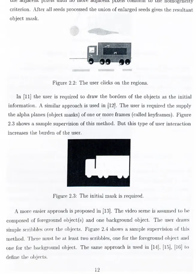
In [10] an image* is se*gmented into homogenous regie)us ae;cordiiig te> a given eaiterion auel tlie; use!r is re*eiuire*.el to the click on the reigions that make* up the* objeect. Figure* 2.2 sheews a sample supervision of this method. The)se* i)e)inls ibrrn the se*e*,els e>f the e:e)iie*s])oneling reigieens. The se*(ids are e*.nlarge*el ley aeleliiig
the adjacent i>ixels until no more adjacent pixels conform to the homogeneity criterion. After all seeds processed the union of enlarged seeds gives the resultant object mask.
Figure 2.2: The user clicks on the regions.
In [11] the user is required to draw the borders of the objects as the initial information. A similar approach is used in [12]. The user is required the supply the alpha planes (object masks) of one or more frames (called keyframes). Figure 2.3 shows a sample supervision of this method. But this tjqre of user interaction increases the luirden of the user.
Figure 2.3: The initial mask is required.
A more easier ai)proach is i)ioposed in [13]. The video scene is assumed to Ix' composed of foreground object(s) and one background object. The us(u· draws simple scribbles ov(ir tin* objects. Figure 2.4 shows a sample super\-ision of this method. There must b(' at least two scribbles, one for the foi'egronnd object and one for th(' background object. The same ai)i)ioach is used in [14], [15], [IG] to dehne the objects.
Figure 2.4; The user draw scribbles on the objects.
Another approach is to mark some points on the boundary of the
Figure 2.5 ^ shows a sample supervision of this method. The algorithm connects the given control points using edge energy and a distance penalty based on graph search techniques.
Figure 2.5: The user marks points on the boundary of the object.
The type of the supervision chosen in the proposed method as described in Chapter 3 is the same as the one shown in Figure 2.4. This approach is easy with respect to the user interaction. Furthermore, the amount of the initial information sup])lied by the scribbles is adequate for the proposed met,hod. It is expected that the sci’ibbles to cover some of the regions that make uj) the objects, in the proposed method the regions are enlarged and mergc'd using a distance measure. The type of supervision shown in Figure 2.2 ma,y not be suitable for this i)urpose especially when there are many objects in the sceiu' and each of them consists of many regions. Drawing a simple scribble for each object
is a lot easier. On the other hand, the type of the supervision shown in Figure 2.5 is not suitable to the nature of the proposed method whose aim is reaching the boundaries of the objects eventually. The main difference of the proj)osed supervised segmentation method, whose details are given in Chapter 3, is in the algorithm which merges regions starting from the initial scribbles to the final segmentation pattern.
2.5
T h e In fo rm a tio n S ou rce For S e g m e n ta tio n
The segmentation process if performed on the available information. This information is obtained in feature extraction step of Figure 2.1. The accuracy of the decision step highly relies on the information obtained in feature extraction. Since each information source carries a different kind of information, the segmentation methods are shaped according the information source they use.
The \'ery first information source used in segmentation is the color information, because it carries the exact boundary information. But it is not possible to extract a semantic meaning out of only color information. Most of the approaches use motion information as a complementary of color information [6]- [9]. The motion information is used for detection and tracking of objects and the exact boundaries are extracted from the color information with the helj) of the available motion information. The motion information is not the only sourcoi for detection and tracking of objects. Change detection, the difference between consecuti\-e frames, can also be used for this purpose [5].
There c'xist nu'thods that make use of only motion information as in [34]. First, cknise motion field between consecutive frames are obtained by using a multi-resolution motion estimation algorithm [34]. Then a set of global motion vectors ar(' det ('rmiiu'd out of the dense motion fields by using an it('rati\’(' v('ctoi· quantization im'thod [34]. Tin; image is scigrnented into homogenous regions using the global motion vectors. Covered and uncovered background aii'.as are
determined b,y examining the motion fields. The experimental results of [-34] show the insufficiency of the motion information alone to locate the exact boundaries of the obj(!Cts.
Each information source in feature space contains invaluable and different information. The fusion of these information sources with a rule-based proc(\ssor is the main idea of [6]. This kind of approach tries to make use of the almost all of the information sources that can be extracted out of a video se(|uenc(i.
2.6
T h e R eq u irem en ts On V id e o O b ject S eg
m e n ta tio n
Depending on the goals there are some requirements on video object segmenta tion. These re(iuirements are posed by the type of the application.
For th(i content-based functionalities and the description of the objects, first of all segiiKuitation methods should be generic. They should be able to deal with all of the typical real-life video sequences [15]. There should not l)e any further assumptions about the video sequence being processed. Otherwisoi, the method will be suitable only for some specific applications and this limit(!(l usage will prevent the method to meet the needs of the content-based multimedia formats.
Anotluu· re(iuir(!inent i)laced on video object segmentation is due to thci storage and com])utational considerations. Because, the amount of data to be j)roc('.ssed is very large for video seciuences with respect to still images or audio data. Even with today’s com])uters, processing video data is an issue. Therefori', tlu' algorithms should takci care about the efficiency. This should be done with th(' limitations of tlu; (uid u.sei· in mind.
In ord(u· to increase the (luality of the segmentation i)roc('ss I,he user interaction can Ix' heli)ful. But, the amount of the user interaction must Ix' minimized in ord(n· t,o kc('p the ])rocess feasible. For instance it is not a good
idea to r(i(|uest th(! initial exact mask of an object as user interaction, since it is a tedious task.
In some cases, the user interaction may not be available. For this kind of applications unsupervised methods should be ernplo3'^ed. But the low ciuality results of the ernploj^ed unsupervised segmentation method with respect to supervised methods should be tolerable for the application.
C hapter 3
W eakly Supervised Still Im age
Segm entation
The main coiitribnlion of this work is presented in this chapter. The i)resented segmentation method reciuires supervision as described in the following section. The method segments the input image into regions. The number of regions is determined from the supervision. The output of the method is the segmentation mask of the iii])ut image.
3.1
T h e Form at o f S u p erv isio n
The user draws scriblrlors on the objects. drawing lines he can dcdiiKi as many obji'cts a,s he can. With tlie help of the scribbles the number of objects in the sceiK' is (hitcuinined. Additionally, the locations of the objects aie roughly obtaino'd. Th('i'(' must bci at least two scribbles: one for the background, one for the foreground objt'ct. 'T'here can be more than one scribble for one ol)j('ct. that, is the scribl)les ne('d not l.o be connected.
The scribbles are ('X])('ct('d to i>ass through all the variations of the
is composed of two regions with black and white colors, the background scribble should pass through both of them.
Figure 3.1 shows an example of supervision for the first frame of Akiyo sequence.
Figure 3.1: The format of scribbles.
3.2
W eak ly S u p erv ised S e g m e n ta tio n M e th o d
The method is composed of iterations. Before the first iteration, the frame is mapped to a graph of nodes. A node is defined to be a set of 4-adjacent pixels. Initiall}^, each pixel constitutes a single node, except the ones on the scribbles. All the pixels on each scribble are taken collectively as a single node.
The pixels of the image are denoted by pjy, where the first subscript i denotes the node number to which the pixel belongs to and the second subscript j is the index of the pixel in its node.
The pixels of the image are discriminated according to their feature vectors. For color segmentation, feature vector of the pixel pij contains luminance (Ip.J and/or chrominance {Up.^ and Vp.j) values of that pixel:
lh>i
yp.
u,
IHj (3.1)IdPi,
For motion segmentation, feature vector of the pixel pij is the motion vector of that pixel:
m-r
^_myJ (3.2)
where rrix and m.y are the horizontal and vertical components of the motion vector oi Pij. The cpiality of the motion segmentation depends on the accuracy of the motion vectors. Due to the ill-posedness of the motion estimation [19], suitable motion estimation methods must be used.
After the initialization step, the iterations start. At each iteration, the distance measure of every link in the frame is computed. A link is defined to be a connection between two nodes in a 4-adjacent manner. The distance measure is defined for the links connecting the 4-adjacent pixels belonging to different nodes. Additionally, the distance measure is not defined for the links between the scribble nodes (the nodes initiated by the scribbles) since it is forbidden to cluster pixels on different scribbles.
Figure 3.2 shows the links between two nodes at an intermediate iteration. Two nodes are shown in Figure 3.2: i?i and i?2- Ri contains 7 irixels and R2
contains 6 pixels. There are two links between Rx and R.2 at different locations: /] and /0. The link U c:onnects the pixels pn and 7J21· The link I2 connects the
pixels pi2 and P22· The search windows (SW) for the corresponding pixels are drawn with dashed lines.
The distance measure of the link I2 in Figure 3.2 is given by :
A^i 2-^22
(3.3) (A^12 T A^22)
where p\2 and P22 are adja.cent pixels belonging to nodes R.i and R2· res]K'cti\’ely. N¡2 is tlu' number of pixi'ls l)elonging to in the SW of p./2! '' sciuare window c,('utered at p,;2. A;2 1« the average feature vec:tor of ])ixels of A, in the corn's])onding SW:
P i2 — J _
M'*2 2k in
E
51Vp., ^^Pik (3.4) where /Xp.^ diuiotes the feature vector of the pixel belonging to hi the corresponding sc'arch window.For the case shown in Figure 3.2 the distance measure of the link l\ is eciual to the distance of measure of the link I2· Because the search windows of the jiixels of both links include all the ])ixels of the corresponding nodes. Hence the avcn age feature \-ectorH and the number of pixels covered by the search windows are ecjual for Pi] and pi2- That is d,i = /9,2 and A^,;i = AT^· Therefore the distance nu'asuri' of tlie links l[ and l·, are equal for this case. For other ca.ses where tlu' search windows do not cover all jiixels of the nodes, the distance iiK’asures will jxissilily be diffen'iit.
The motivation of this distance measure can be described as follows. TIk' squared norm ])ro\’ides that similar regions with respi'ct t,o the feat.un' \-('cl.or
difference in Ixitween will be favored to those regions that have higher dilferenci! in between. That is the distance measure of the link connecting similar regions (of adjacent nodes) will be smaller than the distance measure of the link connecting regions that have higher difference in between. Hence, the nodes that have similar contact regions will possess the privilege to be merged. The second term in Equation 3.3, gives priority to smaller regions in merging procc\ss by increasing the cost of merging larger regions.
The links are defined in 4-adjacent manner, because of the computational considerations. The inclusion of the diagonal neighbors would double the number of the links in the frame. Furthermore, by this definition of distance measure 4- adjacency of the nodes is assured.
At the end of each iteration, the minimum link distance is determined. Then that link is removed and the corresponding nodes are merged. If there are multiple links with the minimum distance, all the links are removed and the corresponding nodes are merged. Hence, merging more than two nodes in one iteration is possible.
The algorithm (uids whenever there is no link to be removed left (that is the node numlrer becomes eciual to the number of objects) or a desired numlxu· of nodes is reaclu'd.
The st(q)s of the algorithm can be summarized as follows: • Map the image to a. graph of nodois.
Each ])ixel (exc('])t the ones on scribbles) is a single node. .\11 the ])ixels on ea.ch scribble constitutes a single node.
• Re])ca.t.
(A)mi>ute th(' distance measure of each link in the graj)!). Find l.h(' link with minimum distance measure.
• until tli(! number of nodes becomes equal to the number of objects or a desii iid number of nodes is reached.
The emphmid distance measure is different than the one in [17]. In [17], the distance measure is calculated using the average feature value of the whole node and the total number of pixels of the nodes. We used local values. Beca.nse the objects consist of variations and if overall characteristics of the nodes are us(id in the distanc(i measure, then the growth of the node will be cut or delayefl in the regions where average distance is high but the neighbor pixels are very close to the pixels of the node in that local area. Furthermore, by our definition, links with different distance measures are allowed between the same nodes. By this way local similarities between nodes are stressed.
The proposed algorithm is similar to the supervised seeded region growing method [18] in a sense. Because in seeded region growing method, the pixel with highest priority is merged to the closest seeded region. The priority is determined by a distance measure: lower the distance, higher the priority. But in our method the growing regions are not necessarily the seeded ones (the ones initiated by the scribbles) onh'. Hence, at early iterations similar pixels are merged to form small nodes. Then, throughout the process these small nodes gather together and form larger ones, in other words new seeds are allowed to emerge.
3.3
C o m p u ta tio n a l C o m p le x ity o f th e M e th o d
The method is composed of iterations. Hence complexity of the method is an importanl. issu('.
For an M X -V imag(', al; the beginning of the iterations the numb('r of the nodois is given by:
Nn = M N + Ay - Ay, ( T a )
where N,^ is (,he number of scril)bles (objects) and Np^ is the numb('r of ])ix(>ls on the scribbicis. Tlie nnmber of links, Nl, can be at most 2nm - m — n. D(!])ending on the siz(i and shape of the scribbles this number will decrease. For the worst case, theixi will be — 1 iterations and total number of computed link distanc(!s will be:
kr--A ^ (3.0)
This upper limit indicates the high computational demand of the method. Some methods can be employed to decrease this high complexity. For instance, adjacent pixels having same feature vector can be considered as a single node at the beginning of the iterations. Or recursive-shortest spanning-tree [17] can be used to segment the image into a desired number of regions, then the scribbles will be introduced. But, it should be guaranteed that the scribbles do not pass over the same region. Another method can be parallel-processing of the injuit image. That is the input image will be divided into blocks and the algorithm will operate on ea.ch block independentl}c
3 .4
R e su lts for C olor
The color segmentation results of five different test images are shown. Tin' search window size is ta.kcn as s('^■en for all of them. The segmentation is pou formed using only luminance values, that is the chrominance values are not used.
Figurt' 3.3 and Figure' 3.4 show the segmentation results for (he first liame of the Akiyo seciuence with different supervision. The objects are segirn'iiti'd snccessfnlly with some' little errors near the object l)Oundaries.
Figure 3.5 sliows th(' segmentation result for the first frame of Mol.lu'r and Daught.ei' s('(]ii('nce. The object is so'grnented successlidly o'xcejjt the regions wlieic background is v('ry similar to the object. Because of the similarity bet.w('('ii (Ik*
■■''i A'-ii ' /
i
(a)
(b) (c)Figure 3.3; A color segmentation result for Akiyo: (a) input image and supervision (b) segmentation mask (c) segmented object.
( h ) (0
Figure 3.4: Another color segmentation result for Akij^o: (a) input image and supervision (b) segmentation mask (c) segmented object.
hair of the mother and the frame of the picture, the object includes some ])ortion of the frame up to the point where the scribble is reached.
Figure 3.6 depicts the segmentation result for the first frame of Coastguard sequence. The boat is segmented almost exactly. The front man is accepted to be belonging to the background, since the scribble does not include him. If lie was expected to l)e a part of the foreground object, the user must have includcid him in the scribble.
Figuix' 3.7 sliows the li'sults for the first frame of Container se(]uence. There are some ('rrors near the upper boundary of the container. Because it is nol- possible to include' the ])oi tioii of the sea, that is above the containei·, in the
Figure 3.5: A color segmentation result for Mother & Daughter: (a) input image and supervision (b) segmentation mask (c) segmented object.
background, since that portion is disconnected with lower part of the sea and the container has more similar regions to that portion of the sea than the sky.
Figure 3.8 shows the result for the frame of Hall Monitor sequence. The results arc not as accurate as the previous ones, because the objects are very small and have similar regions with the background.
The residts indicate the success of the method with exceptions in some cases where the suj)ervision is not very adequate or the foreground and background objects ar(i very similar.
3.5
R e su lts for M o tio n
The motion between two frames is estimated by using a Gibbs-based motion estimation mi'thod [20]. The estimated motion vectors denote the locations of the pixels of the current frame in the previous frame. The search window size is taken to be 7 as in color segmentation.
Figure 3.9 shows a motion segmentation result for tv'o frairies of Motherc'bDaughtc'r sequence. Figure 3.9(a) and Figure 3.9(b) are t he frames for which th(’ motion is estimated. The su[)ervision is shown in Figuic' 3.9(c·). Tlu' motion vc'ctoi's are shown in Figure 3.9(d). Figure 3.9(e) is the segim'iit.ation
(a)
(c)
Figure 3.6: A color segmentation result for Coastguard: (a) input image and supervision (b) segmentation mask (c) segmented object.
mask of the object.
Figure 3.9 shows a motion segmentation result for two frames of Table Tennis sequence. Figure 3.9(a) and Figure 3.9(b) are the frames for which the motion is estimatcid. For this seipience, the 0'·^' and P'* frames are selected, because of the high motion in the seipience. The supervision is shown in Figure 3.9(c:). The motion vectors mv. shown in Figure 3.9(d). Figure 3.9(e) is the segmentation mask of the object.
As expected from the nature of the definition of motion and the eni])lo,yed motion estimation methods, the segmentation based on motion data tends lo be accurate in finding objects but object boundaries are overly sirnj)lified and fine details ol' the boundarii's are lost. Both of the results indicate that tho' d('si)('d
Figure 3.7: A color segmentation result for Container: (a) input image and supervision (b) segmentation mask (c) segmented object.
| 4 *
«0^
(Fi
Figure 3.8: A color segmentation result for Hall Monitor: (a) input image and supervision (b) segmentation mask (c) segmented object.
objects are located successfull}^ Even multiple foreground objects are located with success. But, the boundaries are not as accurate as the color segmentation.
The main i)roblern for motion segmentation is the areas with zero motion vectors. Generally, most of the scene has zero motion vectors. Then, the ])ixcls with zero motion vectors will be the first pixels to be merged into a single node. But, if more than one scribble passes through an area with zero motion vector, then that area will be shared between scribbles with respect to the first one in scan order. This way different scan orders may lead to different segmentation results.
Figure 3.9: A motion si'gmentation result for Mother&Daughter: (a) O'·'' franu' (!)) 25'·^' frame' (c) sui)ervisioii (d) motion vectors (e) segmentation mask.
e 3.10: A motion segmentation result for Table Tennis: (a.) 0'^' fraiiK' (b) I*'' frame (e) sn])er\asion (d) motion vectors (e) segmentation mask.
C hapter 4
B ilkent A nalysis M odel For
S em i-A u tom atic V ideo O bject
S egm entation
Bilkent Analysis Model Version 5 (BAM) for semi-automatic video object segmentation d(!i)ends on the COST211ter Analysis Model [4], [6] and the weakly supervised still image segmentation method presented in Chapter 3.
COST211ter AM is the Test Model of COST21F project group for video object segmentation. Bilkent University participated in COST211ter i)roj(!ct in 1991-1997. Th(! |)roposal of Bilkent University was accepted as the first AM in 199G. Since then the AM evolved to fourth version. In 1998, Bilkent University discontinued COST211 collaboration and worked on the ne.xt semi-automatic version on his own. Therefore the new model is entitled as Bilkent Anal}'sis Model Version 5.
The sup('ia'ision is introduced by the method in Chapter 3. The object tracking is handl<îd In' a ruk'-processor that fuses different sources ofinformation.
'Coo])(n;iti()ii Enropeeiiiie dan.s le ıcîdıcrche .sccioutifiqne et tedmicjue: htt]):/ / www.t.dl ('(:.<l(:ii.i('/('OSl.2ri
4.1
T h e M o d es o f th e B A M
BAM has three modes of operation; the modes automatically progress in a, tyjoical operation.
• Mode 0 is valid for the first frame of the video sequence when the us('r supc'rvision is supplied. This mode is represented by the uppermost Inanch in Figurii 4.1. Since there is no motion information, only su])ervis(id color segmentation is performed. The color segmentation mask is taken to be tlu; final segmentation mask.
• Mode 1 is valid for the second frame of the video sequence. The user supervision is also used in this mode. The modules in Figure 4.1 that uses the initial user supplied data are the supervised color segmentation and supervised motion segmentation modules.
• Modi'. 2 is the automatic mode of BAM. The user superлdsion is no more r(4]uired and the segmentation and tracking process continues automatically.
4.2
T h e S tru ctu re o f th e B A M
The BAM is a modular ai)proach. It is composed of different moduh'S jrerforming different tasks. The inain idea behind the BAM is the fusion of various intermediate r(!sults l)y a set of rules [C], [21]. The intermediate results ai(' olFained from color segmc'utation, motion segmentation, change dihx'ction, and motion conqx'nsation. These results are fused in the rule-proc('ss(n·. Inside' the rule-proc('ssor tluu'e are' twee irmeles. First one distinguishes t.lie' ibre'greeuuel ol)jee:ts aiiel the' ba,e;kgTe)unel. The sex'.onel mode (extracts multi[)le obje'e^ts iieem the· fore<>rounel if there' are теич' than one foregre)und e)bject. Then ])e)si.-])reie4'.s.sing
is applied whenever necessary. The final step is object tracking rule that enables to carry the siii)ervision to next frames.
The results are held in an object memory to be used for the following frames for object tracking.
In order to simplify the process at the beginning the global camera motion compensation and scene cut detection is applied. If a scene cut is detected the previous lesults will not be used in the rule processor.
The BAM is completely independent of the input video sequence. There is no prior assumption about the type or structure of the video seciuence.
The moduhis of the BAM are shown in Figure 4.1 and briefly described in the following subsections.
4.2.1
User Input
This module supplies the supervision information to the model. The format of the user input is the same as the one described in Chapter 3. The user input is required for only the first frame of the video sequence where the object(s) enter into the scene.
4.2.2
A daptive Frame Skip [4]
The BAM oj)crates on two frames: current and reference (the last franu' ])rocessed) frames. The motion is estimated between the current and refei'cnce frames. Therefore the selection of these frames is an important task in order to obtain reliable motion information. In natural video sequenci's the motion between consecutive frames can be very small. To find the frames, which has suificient motion information in between, BAM uses an adaptive frame ski]) method [22], [23].
First, motion betw('('ii th(' reference frame and the candidate fraviK' is estimated using Hierarchical Block Matching (HBM) [24]. Then th(' nnmb('i'
of motion vectors with magnitude greater than a predetermined thrcishold is determined. If the number of motion vectors exceeds a predetermined throishold, it is assumed that sufficient motion information exists and the caiiflidate frame is assigned to be the current frame. If the number of vectors is smaller than the threshold, then a frame is skipped and the next frame is tested until sufficient motion is found.
The two i)arameters described in [4] are chosen as 2.5 and 600, respectivefy, for QCIF ( Quarter Common Intermediate Format) size.
Table 4.1 shows the results of Adaptive Frame Skip for five different video sequences. Actual sequences are longer; only the first 15 processed frame numbers after adaptive frame skip are given in the table.
Video Sequence First 15 frames to be processed
Akiyo
Mother And Daughter Coast Guard Container Table Tennis 0,17,21,28,34,37,41,48,63,68,71,78,81,87,95 0,24,26,28,30,32,36,39,44,46,48,50,52,54,57 0,2,4,6,8,10,12,14,16,18,20,22,24,26,28 0,6,12,18,24,29,34,39,44,49,60,66,71,76,82 0,1,2,3,4,5,6,8,9,10,11,13,14,15,16 Table 4.1: The results of Adaptive Frame Skip
The ri'sults included in Table 4.1 indicate the necessity and usefuliK'ss of Adaptive Frame Skip. The frames that will be processed by the BA.M aie determined according to the nature of the video sequence.
The usage of AdaptiA'c Frame Skip requires the interi)olation of th(' obj(‘ct masks foi' the skii)])ed frames. For this purpose, the zero-order hold is ns(xl. Because it is tin' simj)lest interi)olation filter and the ski])ped frann's corres])ond to an insufficii'nt motion, therefore using zc'io-order hold will not cause gi('at deviations from the true masks [4]. As a more sophisticated int('rpolat.ion iiK't hod. linear inteipolation that mak(-'.s use of the estimated motion can be ns('d [21].
4.2.3
G lobal M otion E stim ation /C om p en sation [25]- [27]
This module (ístimates tlie global camera motion between two succ(!s.sive iraníes, current (//) and reference (It-i), of a video sequence. The comiiensation is performed if an apiiarent motion is found.
An affine motion model that has eight parameters is used. The motion parameters can represent any kind of motion for a rigid plane object [28], including zoom and pan. For every pixel in the reference frame (.'r/._j ,y,_ i) tlui corresponding pixcd in the current frame (xt.yt) is given by [21]:
xt = ---;--- yt = --- —;---- (4.1) The parameters are estimated by regression using only the pixels in thoi background of the reference frame. If a scene cut is detected, then the jiixels in the vertical strips of ten pixels near the left and right borders are used [21].
After the parameters are found, a post-processing is performed to find the failure regions of the model. Performing a full search within a limited area, for the failure regions, the motion parameters are improved. If the failure regions are large, then the model fails.
An apiiari'iit motion is found if magnitude of the any of the parameters is greater than 1.5. Then bilinear interpolation is used for motion compensation [21].
4.2.4
Scene Cut D etection [25]
In a case of a scc'iie cut. the ])revious segmentation results are of no us(' any more. Therefoix'. .seem' cut detc'ction is necessary to decide on the validity of th(' pi'evious j('sults.
The .sc(>n(' cut d('tect()i· finds the difference between the current frame 7/ and the canu'ra motion coni]K'nsat,ed within tin' I)ackground ])ix('ls of tlu' ])re\-ious
frame. If this difference is greater than a predetermined threshold tsc, then a scene cnt is detected and the segmentation process is reset.
1
Nbg X I {.h{p) - IcMC{t){p)Y < tsc
(4.2) Here, Njjc is the number of pixels in the background of the previous frame and ^BG(t-i) background of the previous frame.
4.2.5
Supervised Color Segm entation
The method presented in Chapter 3 is used in this module. It takes two inputs: current frame and the user input. Its output is the color segmentation mask with regions ecpial to the number of the objects given by the user input.
This module is active in Mode 0 and Mode 1 of BAM.
Figure 4.2 shows a sample supervised color segmentation mask for the first frame of Aki3m sequence.
Figure 4.2: A sami)le sui)ervised color segmentation from Akijm soiquence.
4.2.6
Color Segm entation [21]
This is th(' color segmentation module used in Mode 2. It takes two iii])uts: current frame and a, ])redefined number of regions. The nnniber of regions foi·
QCIF is 256 by default. Its output, i?,[, is a mask that has predefined numh(!r of regions.
A recursive shortest spanning tree (RSST) based segmentation method [17] is used to segment the current frame into predetermined number of regions Iniving uniform intensity [21]. One of the advantages of the method is that it does not have any external constraints on the image. Furthermore, the number of regions can be controlled easily and hence the detail level of the segmentation can l)e adjusted.
Initially, R.SST maps the input image into a weighted graph. At the beginning each pixel is a node of the graph. The weight of a nodes is the average luminance and chrominance values of the node. The link distance between nodes are defined for 4-connected neighboring nodes. The distance between two nodes R\ and B.2
is given by [17], [21]:
d№ ,/Z2) = llto,
(4.3)
Here, is the total number of pixels that belong to i?,j and the feature vector /i is the average luminance and chrominance values of the corresponding node :
/i =
1av(j
u,
av(j avy(4.4)
After initialization, RSST computes all link distances. The link with tin' minimum distance is removed from the graph and the corresponding nodcis are merged into a single node. This process continues until predefinc'd nunibi'r of regions is rc'ached.
Figure 4.3 shows a color segmentation mask with 256 regions lor an intermediate iiame of Akiyo sequence.
Figure 4.3: A sample color segmentation from Akiyo sequence.
4.2.7
Local M otion A nalysis [21]
The motion between the current frame, It, and the reference frame //_] is estimated. For this purpose two different algorithms are used in the BAM. The first one is the Hierarchical Block Matching (HBM) algorithm [24]. It is used due to its acceptal)le results and low computational demand [21]. The second algorithm is a Gibbs-based motion estimation [20]. It produces better results but its computational demand is higher than HBM.
In HBM, motion is estimated in three levels. The measurement window sizes of the level 1, 2, and 3 are 32, 16, 4, respectively.For each level search is performed within a search space. The ranges of the search sj)a,ce are 16, 8, and 2, respective!}'. The search space is traversed with steps 2, 2, 1, respectively. Table 4.2 summarizes these parameters. One motion vector is found for each 4.'r4 block. Then zero-order hold interpolation is used to obtain a dense motion field [4].
H ierarchy Level 1 2 3
Measurement window size 32 16 4 Search space range 16 8 2
Search step size 2 2 1
Tal)l(' 4.2: The parameters of HBM
The error critiu'ion is the Mean of Absolute Differences (MAD) between measureirKuit window on the current Y-frame and the search window on the reference Y-frarne. If the search block goes out of the frame, the portion inside the frame is used [21]. The winner motion vector is the one with minimum MAD.
Finally, to force the resultant vector to be (0,0) for a 4x4 block, first MAD for the (0,0) vector is found. A predetermined constant (currently 1) is subtracted from it. If the result is smaller than the MAD of the winner motion vector, then (0,0) vector is accepted. Otherwise, the winner motion vector is preserved [21].
In Gibl)s-based motion estimation a Gibbs energy function is constructed and minimized using Iterated Conditional Modes [20].
If sub-i)ixel accurate motion vectors are requested, the frames are upsampled by two and linearly interpolated. The impulse response of the filter used for interpolation is given by:
/ =
0.25 0.50 0.25 0.50 1.00 0.50 0.25 0.50 0.25
(4.5)
4.2.8
Supervised M otion Segm entation
This module is active only in Mode 1. It takes two inputs; estimated motion vectors and user input. The estimated motion vectors are segmented using the method presented in Chapter 3. Its output is the motion segmentation mask The number of regions in equals to the number of objects.
Figure 4.4 shows a rc'sult of supervised motion segmentation. The result is obtained for the 0'^' and 17'^'· frames of Akiyo sequence (frames I-IG are ski])])ed as descrilK'd in S('ction 4.2.2). The supervision is the same as the one shown in Figure 4.8. HBM is used to find the motion vectors.