SIGNAL PROCESSING BASED SOLUTIONS FOR
HOLOGRAPHIC DISPLAYS THAT USE BINARY
SPATIAL LIGHT MODULATORS
a thesis
submitted to the department of electrical and
electronics engineering
and the graduate school of engineering and science
of b
˙Ilkent university
in partial fulfillment of the requirements
for the degree of
doctor of philosophy
By
Erdem Ulusoy
January 2012
I certify that I have read this thesis and that in my opinion it is fully adequate, in scope and in quality, as a thesis for the degree of Doctor of Philosophy.
Prof. Dr. Haldun M. ¨Ozakta¸s (Supervisor)
I certify that I have read this thesis and that in my opinion it is fully adequate, in scope and in quality, as a thesis for the degree of Doctor of Philosophy.
Prof. Dr. Levent Onural I certify that I have read this thesis and that in my opinion it is fully adequate, in scope and in quality, as a thesis for the degree of Doctor of Philosophy.
Prof. Dr. Orhan Arıkan I certify that I have read this thesis and that in my opinion it is fully adequate, in scope and in quality, as a thesis for the degree of Doctor of Philosophy.
Prof. Dr. Aydın Alatan
I certify that I have read this thesis and that in my opinion it is fully adequate, in scope and in quality, as a thesis for the degree of Doctor of Philosophy.
Assoc. Prof. Dr. U˘gur G¨ud¨ukbay
Approved for the Graduate School of Engineering and Science:
Prof. Dr. Levent Onural
ABSTRACT
SIGNAL PROCESSING BASED SOLUTIONS FOR
HOLOGRAPHIC DISPLAYS THAT USE BINARY
SPATIAL LIGHT MODULATORS
Erdem Ulusoy
Ph.D. in Electrical and Electronics Engineering
Supervisor: Prof. Dr. Haldun M. ¨
Ozakta¸s
January 2012
Holography is a promising method to realize satisfactory quality three-dimensional (3D) video displays. Spatial light modulators (SLM) are used in holographic video displays. Usually SLMs with higher dynamic ranges are pre-ferred. But currently existing multilevel SLMs have important drawbacks. Some of the associated problems can be avoided by using binary SLMs, if their low dynamic range is compensated for by using appropriate signal processing tech-niques. In the first solution, the complex-valued gray level SLM patterns that synthesize light fields specified in the non-far-field range are halftoned into bi-nary SLM patterns by solving two decoupled real-valued constrained halftoning problems. As the synthesis region, a sufficiently small sub-region of the central diffraction order region of the SLM is chosen such that the halftoning error is acceptable. The light fields are synthesized merely after free space propagation from the SLM plane and no other complicated optical setups are needed. In this respect, the theory of halftoning for ordinary real-valued gray scale images is ex-tended to complex-valued holograms. Simulation results indicate that light fields that are given either on a plane or within a volume can be successfully synthesized
by our approach. In the second solution, a new full complex-valued combined SLM is effectively created by forming a properly weighted superposition of a number of binary SLMs where the superposition weights can be complex-valued. The method is a generalization of the well known concepts of bit plane decom-position and representation for ordinary images and actually involves a trade-off between dynamic range and pixel count. The coverage of the complex plane by the complex values that can be generated is much more satisfactory than that is achieved by those methods available in the literature. The design is also easy to customize for any operation wavelength. As a result, we show that binary SLMs, with their robust nature, can be used for holographic video display designs. Keywords: Three-Dimensional Holographic Video Displays, Binary Spatial Light Modulators, Light Field Synthesis, Computer Generated Holography, Halftoning, Full-Complex Modulation
¨
OZET
˙IK˙IL˙I UZAMSAL IS¸IK MOD ¨
ULAT ¨
ORLER˙I KULLANAN
HOLOGRAF˙IK EKRANLAR ˙IC
¸ ˙IN S˙INYAL ˙IS
¸LEME TABANLI
C
¸ ¨
OZ ¨
UMLER
Erdem Ulusoy
Elektrik ve Elektronik M¨
uhendisligi B¨
ol¨
um¨
u Doktora
Tez Y¨
oneticisi: Prof. Dr. Haldun ¨
Ozakta¸s
Ocak 2012
Holografi, yeterli kalitedeki ¨u¸c boyutlu video g¨osterimi i¸cin ¨umit verici bir y¨ontemdir. Holografik video g¨osterimi i¸cin uzamsal ı¸sık mod¨ulat¨orleri (SLM) kullanılır. Genellikle pikselleri geni¸s bir aralıktaki pek ¸cok ayrık de˘geri alabilen SLMler tercih edilmektedir. Ancak mevcut bu t¨ur ¸cok seviyeli SLMlerin ¨onemli sorunları vardır. Pikselleri ikili de˘ger alan SLMler kullanarak, bu sorunların bir kısmından ka¸cınılabilir. Ancak bunun i¸cin, uygun sinyal i¸sleme tekniklerinin kullanılması gerekir. ˙Ilk ¸c¨oz¨umde, b¨uy¨uk olması gerekmeyen uzaklıklarda be-lirtilmi¸s ı¸sık alanlarını sentezleyen karma¸sık de˘gerli gri SLM ¨or¨unt¨uleri, ikili SLM ¨or¨unt¨uleri i¸cine kodlanmaktadır. Bu kodlama sırasında, birbirinden ayrı iki reel de˘gerli yarım tonlama problemi ¸c¨oz¨ulm¨u¸st¨ur. I¸sık alanı, SLMin merkezi kırınım b¨olgesinin yeterince k¨u¸c¨uk bir alt b¨olgesinde sentezlenmektedir. Bu sayede, yarım tonlama hatası kabul edilebilir d¨uzeyde kalmaktadır. I¸sık alan-ları sentezlenirken, do˘grudan uzaya yayılım yeterli olmakta ve ba¸ska bir optik d¨uzene˘ge gerek duyulmamaktadır. Bu ba˘glamda, sıradan reel de˘gerli gri re-simler i¸cin kullanılagelen yarım tonlama teknikleri, karma¸sık de˘gerli hologramlar i¸cin de kullanılmak ¨uzere geni¸sletilmektedir. Sim¨ulasyon sonu¸cları, bir d¨uzlem
¨
uzerinde ya da bir hacim i¸cerisinde verilen ı¸sık alanlarının, bizim yakla¸sımımız ile ba¸sarıyla sentezlenebildi˘gini g¨ostermektedir. ˙Ikinci ¸c¨oz¨umde, fiilen, karma¸sık de˘gerler ¨uretebilen yeni bir SLM olu¸sturulmaktadır. Bu kombine SLM, bir dizi ikili de˘gerler alan SLMin uygun a˘gırlıklı toplamı olu¸sturularak elde edilmek-tedir. Buradaki a˘gırlıklar karma¸sık de˘gerli de olabilmektedir. Bu y¨ontem, sıradan g¨or¨unt¨uler i¸cin iyi bilinen bit d¨uzlemi ayrı¸stırımı ve g¨osterimleri kavram-larının genelle¸stirilmi¸s bi¸cimidir ve seviye sayısı ile piksel sayısı arasındaki bir ¨
od¨unle¸simi i¸cerir. Elde edilen karma¸sık de˘gerlerin karma¸sık d¨uzlemdeki yayılımı, literat¨urdeki y¨ontemlerle elde edilenlere g¨ore ¸cok daha iyidir. Tasarım, iste-nilen herhangi bir optik dalga boyu i¸cin de kolayca uyarlanabilir. Sonu¸c olarak, g¨urb¨uz yapılı ikili SLMlerin holografik g¨osterim sistemlerinde kullanılabilece˘gi g¨osterilmi¸stir.
Anahtar Kelimeler: U¸c Boyutlu Holografik Video Ekranı, ˙Ikili Uzamsal I¸sık¨ Mod¨ulat¨orleri, I¸sık Alanı Sentezi, Bilgisayarda ¨Uretilmi¸s Holografi, Yarım Ton-lama, Tam Karma¸sık Mod¨ulasyon
ACKNOWLEDGMENTS
I would like to express my sincere thanks to my supervisor Prof. Dr. Haldun M. ¨Ozakta¸s and to Prof. Dr. Levent Onural for their guidance, support and encouragement during every phase of this research.
I would also like to thank Prof. Dr. Orhan Arıkan, Prof. Dr. Aydın Alatan and Assoc. Prof. Dr. U˘gur G¨ud¨ukbay for reading and commenting on the thesis. This work is partially supported by European Commission within FP6 under Grant 511568 with acronym 3DTV.
I also acknowledge the financial support of T ¨UB˙ITAK (The Scientific and Tech-nological Research Council of Turkey) between 2004-2009.
It was a hard time for me, but I always felt the sincere support of my dear mother Emine Ulusoy and my dear father Sefa Ulusoy behind me; and needless to say I owe every happiness that I have felt so far in my life to them. Also, my dear sister Banu Ulusoy, to whom I dedicate this thesis, has been my pri-mary source of happiness since she was born and since the beginning of this thesis, and I thank her for being a perfect sister with whom I am so proud of. I know that stories of success within a family do not outcome only as a result of the work of a single generation, but they are the result of the tremendous efforts spent by many past generations. In this respect, I should thank my dear grandmothers ˙Ismahan Yi˘git, Zeliha Ulusoy and my dear grandfathers H¨useyin Ulusoy and Ramazan Yi˘git (who watches me from heaven with proud I hope) with all my sincere respect. I should also include my dear aunt, or my second mother, M¨uzeyyen Arslan with whom I spent most of my childhood, which was
a marvelous one. I am very lucky that I have many excellent friends, most of which I will not be able to list here due to space limitations. They have been the color of my life and I should thank them for sharing every joy or pain with me. Among them, I should mention Erdem S¸ahin (who is closer than a brother to me), Zehra G¨orgel, G¨okhan Bora Esmer, Kıvan¸c K¨ose, Bilge Ka¸slı, Fahri Yara¸s, Ferda Yara¸s, Alexander Suhre, Ali ¨Ozg¨ur Y¨ontem, Alper ¨Unal, Ay¸ca ¨Oz¸cellikkale, Mehmet K¨oseo˘glu, Onur Tan, Yi˘gitcan Eryaman and Re¸sit Teksin. I should also thank my long term friends Onur ¨Onder, Emre ¨Un, C¸ i˘gdem Yurttutan and Eda Co¸skuner from my high school years, and my dear friends Yasemin ¨Onder, Doruk Eker, Sinan Ercan and G¨uray Din¸col from the best and the most joyful project I have ever been involved in. I should also thank my dear students from the 2005-2009, 2006-2010, 2008-2011 and 2009-2012 periods; it was really a pleasure for me to be their assistant. I wish the best of success to all of them. I know that the greatest joy that a teacher can feel is to see his or her students achieve a success. In this respect, I am also indebted to all my teachers starting from the primary school. Again due to space limitations, I do not have the chance to mention most of them here, but I should express my sincere thanks to my primary school teacher S¸ehrinaz Co¸ckun¸cay, who made me a good person, and my high school teachers Ayfer G¨ursoy, Ender C¸ akir, Hatice Ers¨ozl¨u and ¨Unal
¨
Ozmen, who definitely taught me much more than the course contents and who showed me the joy that a person can feel by learning and teaching. Finally, I should thank our department secretary M¨ur¨uvet Parlakay for all her help during the long years I spent in Bilkent. Definitely, many more names should appear here, but I do not have the chance to list them all, and I apologize for this. I close by stating my love and passion to my country, Turkey. I feel very happy to be born in this country and I feel proud to be a citizen of Turkey. I consider this thesis as a form of servitude to my country, and I am proud of that.
Contents
1 INTRODUCTION 1
1.2 Three-Dimensional Displays . . . 2 1.3 Binary Spatial Light Modulators . . . 13 1.4 Organization of the Thesis . . . 15
2 PRELIMINARIES 18
2.1 Basics of Scalar Wave Optics . . . 18 2.2 Basics of Scalar Diffraction Theory . . . 20 2.3 Analysis of Light Field Generated by a Spatial Light Modulator . 28
3 SYNTHESIS OF THREE-DIMENSIONAL LIGHT FIELDS WITH BINARY SPATIAL LIGHT MODULATORS 43
3.1 Effects of Applying a Low-Pass Filter to the SLM Pattern . . . . 46 3.2 Encoding Complex-Valued Oversampled Holograms on Binary SLMs 57 3.2.1 Thin Mask Based Solution . . . 61 3.2.2 Oblique Illumination Based Solution . . . 64
3.2.3 Small Deviations in the Incidence Angle of the Illumination
Wave . . . 76
3.2.4 Binary Pixel Values Other Than±1 . . . 77
3.2.5 Volumetric Synthesis Examples . . . 79
3.3 Conclusion . . . 81
4 FULL COMPLEX SPATIAL LIGHT MODULATORS OB-TAINED FROM BINARY SPATIAL LIGHT MODULATORS 90 4.1 Generic Method . . . 93
4.2 Practical Implementation Using a 4f System . . . 102
4.2.1 An LSI System to Form the Weighted Superposition of Binary SLMs . . . 103
4.2.2 Imposing a Bandwidth Limitation . . . 115
4.2.3 Implementation with a 4f System . . . 120
4.2.4 Discussion About the 4f Setup . . . 122
4.3 Pixellated and Quantized Fourier Plane Masks . . . 125
4.4 Conclusion . . . 130
5 SUMMARY AND CONCLUSIONS 134 5.1 Summary . . . 134
5.2 Conclusions . . . 136
List of Figures
2.1 Impulse response of free-space propagation under Fresnel approx-imation (real part). . . 24 2.2 Low pass filtered version of hz(x, y) (real part). . . . 27
2.3 Ratio of uz(x, y) to hz(x, y) (real part). . . . 28
2.4 1D cross-section of the ratio of uz(x, y) to hz(x, y) (real part). . . 29
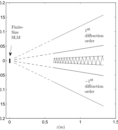
2.5 The sampling and interpolation scheme for pixellated SLMs. . . . 32 2.6 Spatial regions occupied by the diffraction orders of a finite size
SLM. . . 37 2.7 An SLM pattern (real part). . . 38 2.8 Output field produced by the SLM pattern in Fig. 2.7
(magni-tude). Pixels are assumed to be impulsive. . . 39 2.9 Output field produced by the SLM pattern in Fig. 2.7
(magni-tude). Pixels are assumed to be rectangular. . . 42
3.1 Modified scheme for the application of a discrete filter to the SLM pattern. . . 47 3.2 Equivalent scheme to the one displayed in Fig. 3.1. . . 49
3.3 An SLM pattern (real part). . . 52
3.4 Output produced by the SLM pattern in Fig. 3.3 (magnitude). . . 53
3.5 Low pass filtered version of the SLM pattern in Fig. 3.3 (real part). 54 3.6 Output produced by the SLM pattern in Fig. 3.5 (magnitude). . . 55
3.7 Synthesis region (dashed region). . . 56
3.8 Desired light field (magnitude). . . 65
3.9 Ideal SLM pattern (real part). . . 66
3.10 Ideal SLM pattern (imaginary part). . . 67
3.11 Three level SLM pattern for the real part. . . 68
3.12 Three level SLM pattern for the imaginary part. . . 69
3.13 Binary SLM pattern obtained by adding the three level SLM pat-terns in Fig. 3.11 and Fig. 3.12. . . 70
3.14 Light field generated by the binary SLM pattern in Fig. 3.13. . . . 71
3.15 The new binary SLM pattern to be used with oblique illumination. 75 3.16 Light field generated by the binary SLM pattern in Fig. 3.15 under normally incident illumination. . . 78
3.17 Light field generated by the binary SLM pattern in Fig. 3.15 with black pixels being equal to 0 instead of−1. . . 80
3.18 The ideal SLM pattern generating the light field depicted in Fig. 3.19 and Fig. 3.20 (real part). . . 82
3.19 Light field generated by the SLM pattern in Fig. 3.18 at z = 0.8m
(magnitude). . . 83
3.20 Light field generated by the SLM pattern in Fig. 3.18 at z = 1m (magnitude). . . 84
3.21 Binary SLM pattern computed from the ideal SLM pattern in Fig. 3.18. . . 85
3.22 Light field generated by the binary SLM pattern in Fig. 3.21 at z = 0.8m (magnitude). . . . 86
3.23 Light field generated by the binary SLM pattern in Fig. 3.21 at z = 1m (magnitude). . . . 87
4.1 Complex numbers available for a pixel of the new SLM with the weights in Eq. 4.1. . . 95
4.2 Complex numbers available for a pixel of the new SLM with the weights in Eq. 4.2. . . 98
4.3 Division of the complex plane into bins to facilitate the search. . . 101
4.4 1D illustration of the process through which s(x, y) is created out of b(x, y). . . . 105
4.5 Binary SLM pattern. . . 108
4.6 Real part of g(x, y). . . 109
4.7 Imaginary part of g(x, y). . . . 110
4.8 (a) Real part of s(x, y). (b) Imaginary part of s(x, y). . . 111
4.10 Real part of g(x, y). . . 113 4.11 Imaginary part of g(x, y). . . . 114 4.12 Binary SLM Pattern. . . 118 4.13 (a) Full-complex SLM pattern obtained by processing the binary
SLM pattern in Fig. 4.12 with the LSI system described by h(x, y). (b) Resulting diffraction field at 50cm. (c) Full-complex SLM pattern obtained with the LSI system described by hB(x, y). (d)
Resulting diffraction field at 50cm. . . . 119 4.14 4f setup. . . 120 4.15 (a) Fourier plane mask for the weights given in Eq. 4.11. (b)
Pixellated Fourier plane mask that should be used for the weights given in Eq. 4.11. . . 122 4.16 (a) A 4-level Fourier plane mask. (b) Achievable complex
num-bers. (c) Another 4-level mask. (d) Achievable complex numnum-bers. 131 4.17 (a) A 3-level Fourier plane mask. (b) Achievable complex
num-bers. (c) Another 3-level mask. (d) Achievable complex numnum-bers. 132 4.18 (a) A binary Fourier plane mask. (b) Achievable complex
List of Publications
This dissertation is based on the following publications.
[Publication-I] E. Ulusoy, L. Onural and H. M. Ozaktas, “Full-complex am-plitude modulation with binary spatial light modulators,” Journal of the Optical Society of America A, vol. 28, no. 11, pp. 2310-2321, 2011.
[Publication-II] E. Ulusoy, L. Onural and H. M. Ozaktas, “Synthesis of three-dimensional light fields with binary spatial light modulators,” Journal of the Optical Society of America A, vol. 28, no. 6, pp. 1211-1223, 2011.
[Publication-III] E. Ulusoy, L. Onural and H. M. Ozaktas, “Signal process-ing for three-dimensional holographic television displays that use binary spatial light modulators,” in Proceedings of IEEE Conference on Signal Processing and Communications Applications Conference, pp. 41–44, 2010. In Turkish.
[Publication-IV] E. Ulusoy, G.B. Esmer, H. M. Ozaktas, L. Onural, A. Gotchev and V. Uzunov, “Signal Processing Problems and Algorithms in Display Side of 3DTV,” in Proceedings of 2006 IEEE Conference on Image Processing, pp. 2985-2988, 2006.
[Publication-V] E. Ulusoy, V. Uzunov, L. Onural, H. M. Ozaktas and A. Gotchev, “Three-dimensional monochromatic light field synthesis with a de-flectable mirror array device,” in Proceedings of SPIE Volume 6187, 2006.
[Publication-VI] E. Ulusoy, L. Onural and H. M. Ozaktas, “Analysis of the complex light field generated by a deflectable mirror array device,” in Proceedings of SPIE Volume 6252, 2006.
[Publication-VII] E. Ulusoy, L. Onural, H. M. Ozaktas, V. Uzunov and A. Gotchev, “Three-dimensional complex scalar light field synthesis with a de-flectable mirror array device,” in Proceedings of 2nd Workshop on Immersive Communication and Broadcast Systems, ICOB 2005, Berlin, Germany, 2005.
The contributions of the author of this thesis to the publications listed above were as follows: In Publications-I, -II, -III and -VI, the author designed and implemented all of the proposed algorithms and methods, performed the math-ematical derivations, conducted and reported the simulations; and prepared the manuscripts. In Publications-V and -VII, the author designed and implemented all of the proposed algorithms and methods except for those related to the match-ing pursuit algorithm. He performed all of the mathematical derivations; and conducted and reported the simulations related to the algorithms that he de-veloped. In Publication-IV, the algorithm related to the light field synthesis problem was designed and implemented by the author. The related manuscript and simulations were also prepared by the author.
Dedicated to my sister, Banu Ulusoy, to remind her
that my happiness is impossible without her happiness...
Chapter 1
INTRODUCTION
In this thesis, we study the signal processing problems related to the holographic three-dimensional (3D) video displays constructed using binary spatial light mod-ulators (SLM). Binary SLMs have some important advantages over existing mul-tilevel SLMs that make them quite attractive to use in holographic displays. However, minor work has been done to provide satisfactory solutions to the re-lated signal processing problems, perhaps due to the fact that these problems seem challenging at a first glance due to the binary nature of the SLMs. With this work, we try to fill this gap. In the first part of our work, we develop the true approach for synthesizing desired light fields with binary SLMs from a sig-nal processing perspective [1]. This part can be considered as the extension of the classical halftoning theory for two dimensional gray scale real-valued digital images to gray level complex-valued digital holograms. We show through our simulations that, when properly configured, for an observer standing sufficiently far away, a binary SLM can be made indistinguishable from a lower resolution multilevel SLM, resembling the indistinguishability of a standard halftoned 2D image from its original. In the second part of our work, we propose a method for effectively creating a satisfactory full-complex SLM out of binary SLMs [2, 3]. The proposed method is developed using simple signal processing concepts and
can be considered as the generalization of the familiar concepts of bit plane rep-resentation and decomposition for ordinary images to holograms. Again we show through our simulations that with the proposed method, it is possible to effec-tively obtain new SLMs the pixels of which have a better coverage of the complex plane than any existing multilevel SLM, where the new SLMs can function over a broad range of wavelengths within the visual spectrum. We believe that our solutions will provide strong guidance to designers who wish to exploit the ad-vantages of the binary SLMs for constructing a satisfactory quality 3D display. The advantages of binary SLMs are discussed in Sec. 1.3 and the organization of the thesis is detailed in Sec. 1.4. Here, we continue with a review of different approaches for a 3D display and elaborate on the importance of SLMs within this framework.
1.2
Three-Dimensional Displays
To look into images that invoke a depth perception has proven to be an exciting experience for many people. Different methods for capturing and displaying still 3D images have been developed since 1840s [4, 5, 6, 7, 8, 9], and now, thanks to the advances in display and computing technology, it is the time for satisfactory quality 3D video [10, 11, 12, 13, 14, 15], which has already become the rising trend in the visual entertainment industry: every day, an increasing fraction of movies are captured in 3D, more movie theaters improve their infrastructure to deliver these movies, virtually all popular computer games are being designed to deliver 3D graphics, and 3D liquid crystal device (LCD) screens constitute the fashion product on the shelves of consumer electronics stores with the premise that TV channels will be broadcasting 3D content in a few years. All these developments are based mainly on the simple technique of stereoscopy, whose details we briefly explain in the next paragraph.
Natural depth perception in humans is based on various depth cues, such as binocular disparity, motion parallax, convergence, accommodation, occlusion, blurring [16, 17]. 3D display techniques make use of some or all of these depth cues. The simplest method to display a 3D image is stereoscopy, and in its raw form, it makes use only of the binocular disparity: naturally, there is a slight disparity between the images captured by the left and the right eyes of the same object, and stereoscopy takes advantage of this fact [18]. In particular, in stereoscopy, two images of a 3D scene are captured using two cameras placed side by side so as to mimic the two eyes of an observer, and then the image captured by the left (right) camera is presented to the left (right) eye of the observer. In this way, the observer perceives a depth variation in the displayed scene [19, 20, 21, 22]. Mostly, the left and right images are placed on the same screen, but some type of goggles (such as complementary color anaglyphs, polarized glasses or liquid crystal shutter glasses) are worn by the observers to separate the images [23]. Or in some cases, the images are displayed on two different screens placed right in front of each eye, such as in head mounted displays [24]. Stereoscopy is quite easy to implement, and that is why it is the foregoing 3D display technology for the time being. However, there are some limitations and drawbacks of it. To begin with, the necessity to wear the goggles distorts the comfort of the observer. It is possible to avoid the use of goggles at least within a restricted viewing zone by using techniques such as placing a parallax barrier or a lenticular sheet in front of the display. Such techniques are named autostereoscopy [25, 26]. Secondly, in its raw form, stereoscopy only provides binocular disparity, but other visual stimuli provided by it are incorrect. For instance, if a user moves while looking into a 3D object displayed on a standard stereoscopic system, she will recognize that the object will exhibit an unusual parallax. To remedy such problems, researchers developed techniques such as eye-tracking stereoscopy [27], in which the 2D images that are displayed are updated as the position of the observer changes; and multi-view stereoscopy [28], in which several 2D images are
displayed on the same screen where each image is seen only from a specific angle. These techniques provide an improvement to motion-parallax related problems of classical stereoscopy to a certain extent. Yet, there are some intrinsic problems associated with stereoscopy that can never be remedied. For instance, while looking at a stereoscopic display, the lenses of the eyes of an observer are focused at the screen whereas her eyeballs are converged towards the perceived position of the object. This phenomenon is called the accommodation-convergence conflict. It may cause a dizziness after watching for a while, and it will be inevitably present in any stereoscopic system [29, 30].
Actually, a striking peculiarity about stereoscopy that worths mentioning is that it is an already tried and abandoned technique in 3D display history [31]. Actually, the history of stereoscopy is nearly as old as that of conventional 2D photography. Stereoscopic photography was invented in 1838, and the stereo-scopic 3D cinema was available in the early 1900s, but the interest in stereostereo-scopic video was significantly lost after 1950s [32]. Therefore, in a sense, nowadays we are experiencing the rebirth of a once-closed era. The advancement in the con-ventional 2D display technology and the emergence of powerful computers are no doubt the primary reasons for this rebirth. However, the reason for the first failure of stereoscopic video was more than the inconvenient displays and poor computation technology of the day: stereoscopy itself has intrinsic drawbacks and limitations as explained above. Therefore, it is not possible to claim that the ultimate stage has been achieved in 3D display technology yet. In particu-lar, it is well known by scientists for over 60 years that there is an alternative technique which has the potential to vastly eliminate the intrinsic drawbacks and limitations of stereoscopy, namely the holography.
As we mentioned above, the stereoscopic approach for 3D displays mainly takes advantage of a particular depth cue (binocular disparity), and tries to remedy the problems associated with other depth cues as much as possible. The
holographic approach, which has been developed and investigated as a strong candidate to realize the ultimate 3D display following the invention of holography by Dennis Gabor in 1948 [33, 34], takes a route different than focusing on one or more of the depth cues. We can broadly describe the holographic approach for 3D displays as follows: replicate the light that is emanating from the original 3D scene, such that any observer interacting with that light will see the original 3D scene with all its natural depth cues even if the scene is not there physically [31]. Therefore, neither the presence of the observer nor the properties of her visual system are of primary concern. In other words, all of the natural depth cues are aimed to be provided at the same time. As palpably seen, the goals that the holographic approach sets forth are incomparably more challenging than those set forth by the stereoscopic approach. This is why we have to wait more before holographic televisions enter our living rooms. Currently, a holographic TV is possible in principle, but in practice, both the display technology and the associated algorithms need to be improved along a long path before we start seeing satisfactory quality holographic images. But when that path is traveled, there is no doubt that the rewards will worth it.
In its initial form, holography involves the process of making a coherent recording (that is, a recording under illumination by laser light) of the inter-ference pattern between a known reinter-ference wave and the object wave emanating from physically existing objects on a photographic film, which is named after-wards as the hologram [35, 36, 37, 38, 39, 40]. In this way, all the necessary physical properties of the object wave (both intensity and phase) can be cap-tured. During replay, the hologram is illuminated by the same reference wave, and along with several side beams that propagate to different directions, the object wave is reconstructed. In this manner, a quite realistic 3D still image is obtained with all the natural depth cues. In other words, any observer intercept-ing this reconstructed wave sees the correspondintercept-ing object as if it is physically there. Following this line, many scientist devoted their life to the improvement of
the basic technique and development of better photosensitive materials so that better quality images are obtained [41]. Thanks to their efforts, still hologra-phy has enormously excelled in the years that have passed, as can be seen from the amazingly high quality and quite natural-looking color holographic images displayed in several museums and exhibitions [42, 43]. The succession in this area continues to inspire many researchers to channelize their efforts to bring holographic video into reality. Yet, dynamic holography has not yet managed to reach the visual quality offered by still holography. But there is no doubt that when finalized the holographic video display will give a much more fascinating visual experience to observers than any other present technology, as verified by the enormous excitement that people feel when they see a still hologram for the first time.
Though the initial form of holography constitutes the basis on which these exciting ideas about the ultimate 3D display has flourished, there are many mod-ifications that need to be considered on that initial form [44]. To understand the nature of those modifications, let us examine the current trend for the design of a holographic 3D television system [45]. Though from the capture to the display end the conventional 2D television systems evolved from a fully analog system (recording by analog cameras, broadcasting analog TV signals, display using analog cathode ray tube (CRT) screens) to a fully digital system (recording by digital cameras, broadcasting over internet or through satellite systems, display on digital LCD monitors), it seems that the holographic 3D television will emerge as a full digital system; simply due to the reason that analog holographic record-ing and display facilities are inconvenient to support dynamic operation, whereas digital counterparts are much more suitable and flexible. Several recently con-ducted large scale research projects carried on the topic roughly envision the following sequence of operations in an end-to-end holographic 3D television sys-tem [11, 46, 47, 48]:
• Capture the necessary visual information about a 3D scene using multi-camera systems
• Prepare an abstract computer graphics representation of the 3D scene • Transmit that information to the display end
• From the abstract description of the 3D scene, digitally compute the holo-gram of the 3D scene
• Write this hologram on a convenient dynamic holographic screen and dis-play it
From the above list, we recognize that most possibly, the principles of holography will be utilized merely at the display end for delivering the necessary visual signal to an observer. In particular, examining the first three items of the list, we recognize that most probably the depth information about a 3D scene will not be captured through an ordinary holographic recording. Rather, that information will be captured and conveyed to the display end using straightforward extensions of already existing capture, computer graphics and communications techniques. (Actually, we should mention that direct capturing of holographic fringe patterns is still a living alternative [49]. However, for the time being, this alternative seems to be somewhat inconvenient compared to the scheme presented above. One of the main reasons of this inconvenience is that, in this alternative, the 3D scene must be illuminated by coherent light, and this is impractical especially for large scale scenes. Also, the recording camera should be accompanied by an optical setup so that a reference wave is provided. Moreover, current resolution of digital cameras is much lower than that of photographic films, and this places a severe limit on the sizes of the objects that are wished to be imaged [50]. In this respect, we will continue with the scheme mentioned above since it is a stronger alternative.) Then, at the display end, the hologram of the abstractly described 3D scene will be computed just because that hologram is necessary to
produce the final light signal that is to be intercepted by observers. (Actually, in strict terminology, we only need to compute the complex-valued object wave, not the hologram, which corresponds to the interference pattern between the object wave and a reference wave. Note that in the holographic method of Gabor, the interference pattern is formed because the photosensitive materials can only record intensity patterns, not complex amplitudes. But now, electro-holographic displays already have the capability to provide complex values. Therefore, there is no need to form the interference pattern any more, so computation of the object waves is sufficient. But despite making this remark, for the sake of convenience, we will keep on saying that the hologram of the 3D scene must be computed, where it is meant that the cross section of the object wave must be computed over the hologram plane.) From this discussion, we see the modifications that need to be considered over the initial form of holography within the context of a 3D display: in ordinary holography
• the hologram is obtained physically, but now it should be computed; and • the hologram is ready on a piece of photographic material, but now it
should be written on some kind of dynamic device.
Each one of these problems has a unique character and is challenging [51, 52]. Actually, these problems form the bottleneck of holographic video systems for the time being. It is not possible to claim yet that the developed methods for these problems fully fulfill the expectations. Regarding the first problem, the current computational techniques are neither accurate nor fast enough to enable satisfactory real-time operation [53, 54, 55, 56, 57, 58]. Regarding the second problem, the spatial resolution of current holographic video displays are much lower compared to that of photographic films. In addition, the dynamic range of these displays are much lower or restricted compared to that offered by photographic films. Such constraints and restrictions place a limit on the quality of holograms that can be displayed on these devices. These restrictions can be
partially compensated with computational techniques, but these again are not developed to their final form yet by any means [59, 60].
Actually, the two problems discussed above emerged long before the technol-ogy advanced to the level that made a modest holographic television possible. Beginning from early 1960s, following the formulation of scalar wave optics theory of light within a signals and systems framework under the name Fourier optics, holography has also been investigated using signals and systems theory concepts [61]. And beginning from late 1960s; following the invention of computers and the development of the digital signal processing tools, holography has been in-vestigated within a digital signal processing framework [62]. Many new problems have been defined and studied in this context, and many new sub research fields emerged. To name the most important ones, in the so called digital holography, which emerged mainly following the invention of the charged coupled devices (CCD) and cameras built using them, instead of using a photographic film, the hologram of a 3D object is captured using a digital CCD camera, and then the resulting holographic image is processed by a computer to extract the object wave and perform some diagnostics afterwards [49, 50, 63]. And in the so called computer generated holography, instead of performing a physical recording, the holograms that synthesize certain desired beams (that possibly never existed be-fore) are computed digitally using a computer [64, 65, 66, 67, 68, 69, 70]. Then, a physical transparency is prepared from these digitally computed holograms and optical reconstructions are performed. Research is ongoing with increasing pace in all these fields to improve the quality of optical reconstructions while increas-ing the computational performance of the related algorithms as much as possible. And as seen in conjunction with the previous paragraph, there is no doubt that this research (especially the one on computer generated holography) has quite direct contributions towards the development of a 3D holographic television sys-tem. Therefore, we continue with a review of the achievements in computer generated holography.
The research on computer generated holography was initiated by Brown and Lohmann in late 1960s [71]. The goal of these researchers was to compute and produce optical masks that synthesized certain desired light distributions. They faced two important problems. The first one was, at that time, they did not have the required computational power for calculating the hologram that would synthesize a light field specified over an arbitrarily shaped volume and at an arbi-trary distance from the hologram. To overcome this difficulty, they concentrated on small planar regions of space that lied in the far field, so that the relation between the samples of the hologram and the desired light field is to a very good approximation given by a discrete Fourier transform, which was rather easy to compute. The second problem they faced was, the only available devices that had the spatial resolution required for the physical production of the mask were black and white ink-jet dot printers, so that the final mask could only be binary. They resolved this issue by developing their famous detour phase method, which is actually a method for encoding a complex-valued hologram pattern into a bi-nary pattern (we briefly explain the details of this method in the introduction of Chapter 3) [72, 73]. For a quite long time (till early 1980s), only binary masks could be produced, so the detour phase method was used abundantly in com-puter generated holography related applications [74, 75, 76, 77, 78, 79]. Later, following the advancements in both computational and optical technologies, it become possible to efficiently compute holograms for non-far field light distribu-tions and write these holograms on pixellated masks (usually named diffractive optical elements) where more than two values were available for a pixel of the mask. And following the advancement of spatial light modulator (SLM) technolo-gies in late 1980s, computer generated holograms were started to be written on SLMs, which are basically optical masks that can be dynamically programmable [80, 81, 82, 83]. Actually, it is only after the advent of SLMs that holographic video has been considered as a state of technology that can be achieved within several decades. And today, SLMs continue to be the most promising devices
to be employed during the build-up of a satisfactory quality holographic display. Understanding the current state of the SLM technology is therefore crucial for understanding how far away we are from having satisfactory quality holographic displays.
There are many different types of SLMs working with different mechanisms [61, 84, 85, 86]. A large number of SLMs exploit the anisotropic nature of twisted nematic and ferroelectric liquid crystals to modulate the phase of light in a controlled manner. Some SLMs are mirror based. These SLMs consist of an array of quite small mirrors which can be tilted or deformed, so that light is spatially modulated. Yet some other SLMs make use of quantum mechanical or acoustical effects. We will not delve into a detailed discussion of the physics behind SLMs, but rather focus on the behavioral properties of SLMs. From a behavioral perspective, there are a number of different classifications that needs to be mentioned. One such classification is made according to the structure of the hologram that can be written on the SLMs: on some SLMs, a continuous function of position is written. In this case, the SLM is said to be analog. An example is the surface acoustic wave SLMs. On the other side are SLMs the hologram on which is of pixellated structure. Such SLMs are named pixellated or digital SLMs. Today, most SLMs belong to this group. Compared to analog SLMs, digital SLMs are usually much convenient to use; however, the pixellated nature of digital SLMs create some undesired effects such as diffraction orders, i.e., replicas of the main desired beam that flow in different directions. These effects may be disturbing especially within the context of holographic displays. Another classification is according to the nature of the control signals. Some SLMs are electrically addressed while some others are optically addressed. Though the optically addressed SLMs have some advantages over the electrically addressed ones (such as having a shorter response time), it seems that the latter will be more convenient to use in holographic displays, since with the former, the optical setups get quite complicated. Yet another classification is made according to the
way the illumination light is sent to the SLM. Some SLMs are of reflective type, that is, the SLM modulates and reflects back the incoming light. In this case, the illumination wave is sent from the front side of the SLM. The other SLMs are of transmissive type, in which case the illumination wave comes from behind, passes through the SLM while getting modulated, and then leaves the SLM from the front side. Though it seems at a first glance that optical setups would be less complicated with transmissive SLMs, some reflective SLMs (especially mirror based SLMs) have certain advantages that prevent them from getting excluded from consideration.
Perhaps, from the standpoint of holographic displays, the most important behavioral classification among the SLMs is made according to the type of mod-ulation that they can provide. This classification is especially important because the richness of the light fields that can be synthesized with an SLM directly de-pends on the modulation capabilities of the SLM. Note that in general hologram patterns are complex-valued functions of position, meaning that at each spatial position, we require simultaneous and independent amplitude and phase control. Therefore, ideally SLMs should provide full-complex modulation. However, a satisfactory full complex SLM has not been developed yet. Virtually all SLMs provide only some restricted type of modulation. For instance, some SLMs can only provide phase modulation on the incoming light, and they are called phase-only SLMs. A phase-phase-only SLM therefore places on a designer the restriction that all holograms must be phase-only. That is, if the hologram that generates a desired light field is complex-valued, the designer must find a way to encode that hologram into a phase-only pattern. Similarly, some SLMs provide only amplitude modulation and called amplitude only SLMs. But as mentioned, it is nearly impossible to find an SLM that provides both types of modulation simul-taneously in a satisfactory manner. For the digital SLMs, usually, there is also the quantization constraint: pixels of most SLMs can be set only to a finite num-ber of different values. Therefore, it is not possible to cover the complex plane
in a continuous manner. Rather, hologram values are quantized to the nearest available level. Altogether, these constraints impose a limit on the range of the light fields that can be synthesized with these devices. Given a desired field, determination of the best hologram pattern subject to the SLM constraints is a widely studied signal processing problem [51, 52, 87, 88, 89, 90, 91, 92, 93, 94]. For SLMs that have a large number of available values for a pixel (such as an 8-bit phase only or amplitude only SLM), this problem is relatively easy, but for some other SLMs (especially the ones on which the quantization constraint is harsh, such as binary SLMs), the problem becomes more interesting and chal-lenging. Actually, in this thesis, we undertake the signal processing problems that arise in the case of binary (or harshly quantized) SLMs.
1.3
Binary Spatial Light Modulators
The most constrained SLMs are the binary ones. Pixels of binary SLMs can be set to only two possible distinct values such as (0,1) or (−1,1). In this case, the quantization constraint on the SLM is quite harsh. Not surprisingly, when other parameters such as number of pixels, pixel periods etc. are kept the same, the range of the light fields that can be synthesized is the most limited when a binary SLM is used. In addition, determination of a binary hologram that generates a desired light field is more difficult than determining a multilevel hologram. With these difficulties in mind, it is natural to question why a binary SLM might be preferred at all over already existing multilevel SLMs.
Binary SLMs have several important advantages over multilevel SLMs that make them attractive to be used in holographic displays. To begin with, most multilevel SLMs work in the prescribed manner around a certain wavelength. When the wavelength is changed, the pixel values usually change in a drastic
manner. These changes are hard to keep track of especially in multi-color appli-cations such as 3D displays. On the other hand, amplitude-only binary SLMs (such as the digital micromirror devices (DMD) produced by Texas Instruments [95, 96, 97, 98]) provide the same (0,1) modulation independent of the wavelength of the illumination wave. In this respect, their behavior is much easier to keep track of in a multi-color application. (Actually, we show in Chapter 3 that even if the pixel values of a binary SLM change with the illumination wavelength, as long as the new values are still distinct, that change is inconsequential for observers.)
Secondly, most multilevel phase-only (or amplitude-only) SLMs are actually imperfect in the sense that in addition to the phase (amplitude) modulation that they provide, they perform an uncontrollable amplitude (phase) modulation, as can be seen from their operation curves. Therefore, they are not robust in this sense. On the other hand, since binary SLMs only provide two different complex values (and these values are not important as long as they are distinct), they are much more robust.
As a third factor, miniaturization of binary SLMs, that is, manufacturing bi-nary SLMs with small pixel pitches and high pixel counts seems to have a higher potential compared to other types of SLMs, especially when the emerging micro-electro-mechanical systems (MEMS) and micro-opto-micro-electro-mechanical systems (MOEMS) technologies are considered [99]. Actually, it seems that the develop-ment in the binary SLM technology will most likely be in the form of improvisa-tions of the DMD concept. DMDs are most popular in current projection systems for their high light throughput and high contrast ratio. (Actually, DMDs provide perfect contrast in the sense that a blank pixel sends no light to the output im-age. This is quite impossible to achieve with an LCD SLM for instance, the blank pixels of such SLMs always transmit a certain nonzero optical power.) Therefore,
as additional advantages of binary SLMs, we can list their high contrast ratio and light throughput.
Despite these important advantages of binary SLMs, we see that until today the signal processing problems related to the usage of binary SLMs in holo-graphic displays have not been solved to a satisfactory degree. Especially when holographic displays are of concern, almost all of the methods developed so far turn out to be somewhat inadequate, both from a theoretical and a practical perspective. And to our belief, the poor results obtained with those inadequate methods caused the binary SLMs to have a bad reputation among scientists and practitioners. Many designers have mistakenly thought that because of their low dynamic range, binary SLMs are intrinsically inadequate for holographic display purposes, especially in terms of the quality and richness of light fields that can be synthesized. As a result, they mostly abandoned binary SLM based display designs, and shifted their interest into multilevel SLMs. While doing so, they also lost the chance to enjoy the many advantages of binary SLMs over multilevel SLMs. This point stroke our attention when we decided to undertake this thesis [100, 101, 102, 103]. And we believe that with this thesis, we develop the correct approaches for the mentioned signal processing problems. We expect that after this study, researchers will dismiss their negative attitudes towards binary SLMs, and consider the usage of them more seriously in holographic displays.
1.4
Organization of the Thesis
In accordance with the usual practice in holographic research, we also develop our solutions in this thesis using the scalar wave optics theory of light. In this respect, in Chapter 2, we review the basics of scalar wave optics theory and scalar diffraction theory. Moreover, in that chapter we carry out an analysis of the light field generated by a finite size SLM. The results of this analysis is important for
both understanding the solutions we develop for binary SLMs and understanding the usage of SLMs in a holographic display.
In Chapter 3, we undertake the problem of the computation of a SLM pat-tern that generates a desired light field. We start by a review of the proposed methods and algorithms, which are mainly designed for far field or Fourier plane reconstructions. Then, we develop our approach assuming that the desired light field is synthesized within a volumetric region in the non-far field range merely after free space propagation from the SLM plane. In particular, we show that when the desired field is confined to a sufficiently narrow region of space, the ideal gray level complex-valued SLM pattern generating it becomes sufficiently low-pass (oversampled) so it can be successfully halftoned into a binary SLM pattern by solving two decoupled real-valued constrained halftoning problems, which can be solved using already existing algorithms for classical image halftoning. Our simulation results indicate that when the synthesis region is considered, the bi-nary SLM is indistinguishable from a lower resolution full complex gray level SLM. In an other sense, by the end of that chapter, we will have extended the theory of halftoning for classical gray level images to holograms.
In Chapter 4, we take a different route and develop a solution for effectively creating a full complex SLM using a number of binary SLMs. Again, we start by reviewing several full complex modulation schemes developed using multilevel SLMs. Then we discuss our solution which is based on on simple signal processing concepts. We first propose a generic method, by which, out of K binary (or 1-bit) SLMs of size M × N, we effectively create a new 2K-level (or K-bit) SLM
of size M × N. The method is a generalization of the well-known concepts of bit plane representation and decomposition for ordinary gray scale digital images and relies on forming a properly weighted superposition of binary SLMs. When K is sufficiently large, the effective SLM can be regarded as a full-complex one.
That 4f system also provides a means for eliminating the undesirable higher diffraction orders, and the components of the 4f system can easily be customized for different production technologies. By the end of this chapter, we will have developed a method for utilizing binary SLMs as efficiently as possible from an information theoretical perspective towards achieving full complex modulation.
Chapter 2
PRELIMINARIES
2.1
Basics of Scalar Wave Optics
Until today, four major theories have been developed to explain optical phe-nomena [104]. From the simplest to the most complex, these theories are listed as
• geometric optics theory, in which light is described by rays that travel according to Fermat’s principle,
• scalar wave optics theory, in which light is described by a scalar function of position and time that satisfies the wave equation
• classical electrodynamic theory, in which light is described by four vector-valued functions of position and time (electric field, magnetic field, electric flux density, magnetic flux density) that satisfy the Maxwell equations • quantum electrodynamic theory, in which light is postulated to consist of
photons which exhibit both wave-like and particle like characteristics. The behavior of photons are governed by quantum mechanical principles.
The geometric optics theory is adequate in partially explaining phenomena such as reflection, refraction, imaging; and the behavior of simple optical compo-nents such as lenses, prisms, mirrors etc. However, it fails to explain phenomena such as interference and diffraction (“any deviation of light rays from rectilin-ear paths which cannot be interpreted as reflection of refraction”, as defined by Sommerfeld) in which the wave nature of light becomes predominant. Scalar wave optics theory enters the picture at this stage and it accounts for most phe-nomena related to wave nature of light. Yet, it is not sufficient to fully explain the nature of energy transport by light waves, it does not accurately describe diffraction at high angles, it fails to account for the behavior of more advanced optical components such as polarizers and optical crystals, and it does not estab-lish the link between the sources of radiation and the radiated waves in a precise manner. Therefore, in the course of history, it is replaced by the classical elec-trodynamic theory, which virtually explains all the optical phenomena within classical confines. Following the development in quantum mechanics, classical electrodynamic theory is refined to the quantum electrodynamic theory in order to account for light-matter interactions that occur at the quantum scale as well. In this thesis, we are only interested in optical phenomena that arise within the context of holography. Historically, the holographic method was developed using the scalar wave theory of light. And until today, scalar wave theory has proven to be sufficient for most holographic applications, making it unnecessary to resort to a more advanced theory of light. Therefore, here, we use the scalar wave theory of light as well, and we continue with a brief summary of that theory. According to the scalar wave theory, light is described by a scalar real-valued function of space and time that we denote by ˜u(x, y, z, t) with x, y, z ∈ R denot-ing the three spatial cartesian coordinates and t ∈ R denoting the time. It is postulated that ˜u satisfies the so-called wave equation in free-space:
∇2u˜− 1
c2
∂2u˜
where ∇2 = ∂2
∂x2 +
∂2
∂y2 +
∂2
∂z2 and c denotes the speed of light in free space. Mostly, we are interested in purely monochromatic light disturbances. If the light is monochromatic, at every point in space, ˜u takes the form ˜u(x, y, z, t) = A(x, y, z) cos{2πλct− ϕ(x, y, z)} where A and ϕ are real-valued functions of po-sition and λ denotes the wavelength of the monochromatic light disturbance. In such cases, as well known, it is more convenient to work with phasors. If we define a complex-valued function of position that we denote by u(x, y, z) such that u = Aejϕ, then we have ˜u =R{ue−j2πλct
}
so that ˜u can be recovered easily if we know u over the spatial region of interest. u is usually named the phasor that describes the light. In the rest of the thesis, we assume that we are dealing with monochromatic light disturbances and we use phasors. Note that if ˜u is to satisfy Eq. 2.1, u has to satisfy the so called Helmholtz equation:
∇2u + k2u = 0 (2.2)
where k is usually named the wave number and is given by k = 2π
λ . (2.3)
2.2
Basics of Scalar Diffraction Theory
A well known problem investigated under scalar wave optics theory is the so called diffraction problem, in which it is assumed that u(x, y, z) is known over a planar surface, and the objective is to determine it at some other region of space where there is only free-space propagation in between. Usually, the planar surface is taken as the z = 0 surface, the light waves are assumed to be propagating from the z < 0 half-space towards the z > 0 half-space, and the points of interest lie in the z > 0 half-space. Hence, given u(x, y, 0) for all x, y; the goal is to determine u(x, y, z) for all x, y and z > 0 such that u(x, y, z) satisfies the Helmholtz equation given by Eq. 2.2. Though there is fundamentally no difference in between, in most
references on the subject, the problem is posed as the determination of u(x, y, z) as a two dimensional function of x and y for some constant z > 0. That form is also convenient for our purposes in this thesis. When the problem is posed in that form, it is more convenient to denote the light field over the z = 0 plane by u0(x, y) instead of u(x, y, 0). Similarly, the light field over an arbitrary z−plane
is more conveniently denoted by uz(x, y). Since this notation is more common,
from now on we also switch to it. To summarize, in the diffraction problem, we assume that u0(x, y) is specified, and the goal is to determine uz(x, y) for some
constant z > 0.
As explained in [61], the relation between u0(x, y) and uz(x, y) is given as a
linear shift invariant (LSI) system:
uz(x, y) = u0(x, y)∗ ∗hz(x, y) = ∫ ∞ −∞ ∫ ∞ −∞ u0(x′, y′)hz(x− x′, y− y′)dx′dy′ (2.4)
where∗∗ denotes two-dimensional analog convolution operation and hz(x, y)
de-notes the impulse response of free space propagation. According to the Rayleigh-Sommerfeld (RS) theory, hz(x, y), i.e., the impulse response of free-space
propa-gation, is given as:
hz(x, y) = − 1 2π z R (1− jkR) ejkR R2 (2.5)
where R = √x2+ y2+ z2. The Fourier transform (FT) of Eq. 2.5, i.e., the
frequency response of free space propagation is given as [105, 106]: Hz(νx, νy) = F {hz(x, y)} = ∫ ∞ −∞ ∫ ∞ −∞
hz(x, y) exp{−j2π (xνx+ yνy)} dxdy
= exp { jkz √ 1− (λνx)2 − (λνy)2 } . (2.6)
Note that if U0(νx, νy) and Uz(νx, νy) respectively denote the Fourier transforms
of u0(x, y) and uz(x, y), we have Uz(νx, νy) = Hz(νx, νy)U0(νx, νy).
Eq. 2.5 and Eq. 2.6 are exact solutions of the diffraction problem within the confines of the scalar wave optics theory. In these equations, in addition to
the propagating plane wave components, evanescent waves are also taken into account. Since evanescent waves decay very quickly, for z≫ λ, their contribution can be ignored and Eq. 2.5 and Eq. 2.6 can be taken as
hz(x, y) = z jλ ejkR R2 (2.7) and Hz(νx, νy) = exp { jkz√1− (λνx)2− (λνy)2 } for (λνx)2+ (λνy)2 ≤ 1 0 otherwise . (2.8) Ignoring the effects due to the slowly changing amplitude term jλz R12, we can see that the instantaneous spatial frequencies of hz(x, y) along x and y directions
are given by νX(x, y) = 1 2π ∂{kR} ∂x = x λR (2.9) and νY(x, y) = 1 2π ∂{kR} ∂y = y λR. (2.10)
Note that νX(x, y)2 + νY(x, y)2 is always less that λ12 in accordance with the propagating wave constraint.
Under paraxial cases, that is,
• either u0(x, y) is a sufficiently low-pass function,
• or u0(x, y) is confined to a narrow region around the optical axis and we
are only interested in the portion of uz(x, y) lying close to the optical axis,
we can utilize the commonly used Fresnel diffraction theory, in which the impulse response is approximated with a chirp (quadratic phase exponential) function:
hz(x, y) = ejkz jλze jπ λz(x 2+y2) . (2.11)
The corresponding frequency response becomes Hz(νx, νy) = ejkzexp { −jπλz(ν2 x + ν 2 y) } (2.12) which is also a chirp. Note that under the Fresnel approximation, the instanta-neous frequencies are also approximated as:
νX(x, y) = x λz (2.13) and νY(x, y) = y λz. (2.14)
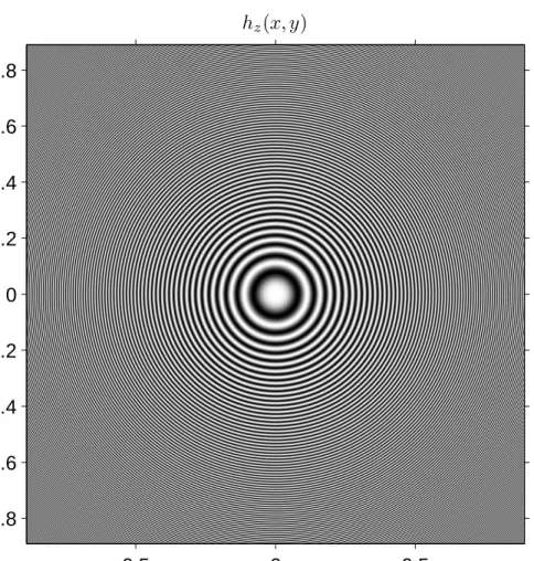
Hence, under the Fresnel approximation, the instantaneous frequencies are as-sumed to vary linearly with the spatial coordinates. The impulse response given in Eq. 2.11 is illustrated in Fig. 2.1 (λ = 632.9nm, z = 1m). From this figure, we can clearly see that the instantaneous frequencies increase as we get away from the origin.
Having reviewed the basics of scalar diffraction theory, now we will examine the output field generated by a special input field in detail since that input field will be important for our developments in the rest of the thesis, especially during the analysis of the light fields generated by spatial light modulators (SLMs). In this respect, we will first concentrate on a useful approximate formula for the output fields generated by input fields that have a sufficiently narrow spatial support. We begin the discussion by considering the Fresnel diffraction case. Substituting hz(x, y) given by Eq. 2.11 into Eq. 2.4, we can explicitly write
uz(x, y) = ejkz jλze jπ λz(x 2+y2)∫ ∞ −∞ ∫ ∞ ∞ u0(x′, y′)e jπ λz(x′2+y′2)e− j2π λz(x′x+y′y)dx′dy′
from which we see the well known fact that chirp convolution is equivalent to pre-multiplication with a chirp, taking a Fourier transform, and then post-multiplication with another chirp. Now, suppose the input u0(x, y) is
concen-trated around the origin and has a sufficiently narrow support. Also assume that z is sufficiently large. In this case, we can write
u0(x′, y′)e
jπ
hz(x, y) x(cm) y (c m ) −0.5 0 0.5 −0.8 −0.6 −0.4 −0.2 0 0.2 0.4 0.6 0.8
Figure 2.1: Impulse response of free-space propagation under Fresnel approxi-mation (real part).
which is essentially equivalent to assuming that over the narrow spatial support of u0(x′, y′), the chirp term e
jπ
λz(x′2+y′2) can be taken as unity. This assumption
leads to the following approximate formula: uz(x, y) ≈ ejkz jλze jπ λz(x 2+y2) U0 ( x λz, y λz ) ≈ hz(x, y)U0 ( x λz, y λz ) . (2.15)
Actually, using Eq. 2.13 and Eq. 2.14, we can write Eq. 2.15 in the following form as well:
uz(x, y)≈ hz(x, y)U0(νX(x, y), νY(x, y)) . (2.16)
Note that we arrived at the above result by viewing u0(x, y) as the input field
and uz(x, y) as the output field. However, sometimes, it is more convenient to
view u0(x, y) as an arbitrary function (with a narrow spatial support as before)
with which we convolve hz(x, y), and uz(x, y) as the result of that convolution.
In that respect, we write Eq. 2.16 in the following form for easier reference in future:
u0(x, y)∗ ∗hz(x, y)≈ hz(x, y)U0(νX(x, y), νY(x, y)) . (2.17)
We arrived at Eq. 2.16 using the Fresnel diffraction formula. However, as long as u0(x, y) is sufficiently narrow, Eq. 2.16 can be used with the
Rayleigh-Sommerfeld diffraction formulas as well, giving uz(x, y)≈ z jλ ejkR R2 U0 ( x λR, y λR ) . (2.18)
Now using these approximate formulas, let us consider the input given as u0(x, y) = BxBysinc(xBx)sinc(yBy) (2.19) with sinc(x) = sin(πx) πx for x̸= 0 1 for x = 0 .
We assume that Bx2 + By2 < λ12 and Bx−1 and By−1 range between several λ and
the Fourier transform of u0(x, y) is given by U0(νx, νy) = rect ( νx Bx ) rect ( νy By ) (2.20) with rect(x) = 1 for −0.5 < x < 0.5 0.5 for x =±0.5 0 otherwise .
Note that u0(x, y) in Eq. 2.19 can also be viewed as the impulse response of an
ideal low-pass filter with a rectangular frequency support and bandwidths Bx
and By. In this respect, we can also view uz(x, y) as the low-pass filtered version
of hz(x, y). In Fig. 2.2, uz(x, y) is displayed for z = 1m, λ = 632.9nm, Bx =
By = 0.01λ , and hz(x, y) as given in Eq. 2.11. As seen, uz(x, y) is approximately
equal to a windowed version of hz(x, y) (please compare Fig. 2.2 to Fig. 2.1).
Actually, the approximation in Eq. 2.16 also predicts this result, i.e., when we apply that approximation, we get
uz(x, y)≈ hz(x, y)rect ( νX(x, y) Bx ) rect ( νY(x, y) By ) . (2.21)
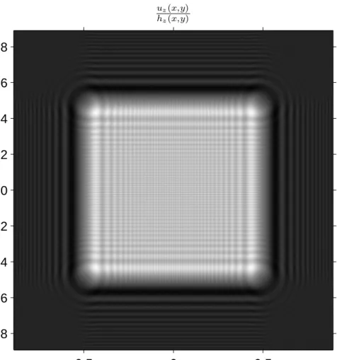
For a better comparison, in Fig. 2.3, the ratio of uz(x, y) to hz(x, y) is
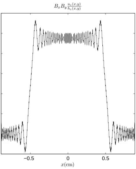
dis-played, while in Fig. 2.4, a 1D cross-sections of that ratio is shown. From these figures, we see that the rectangular window predicted by the approximate for-mula is in fact not a perfect one: there are ripples within the window and there are nonzero terms outside the window. However, we see that the approximate formula is quite successful in predicting the support and overall shape of uz(x, y).
Actually, when Bx, By and z are kept within suitable ranges, the approximation
in Eq. 2.21 works fine for our purposes. For instance, the approximation holds with a normalized mean squared error that is less than 5% when Bx−1 and By−1 are between λ and 100λ, and z is greater than about 7.5×10⁵λ. These ranges for Bx, By and z are of interest to us in this thesis, and the indicated approximation
uz(x, y) x(cm) y (c m ) −0.5 0 0.5 −0.8 −0.6 −0.4 −0.2 0 0.2 0.4 0.6 0.8
Figure 2.2: Low pass filtered version of hz(x, y) (real part). First appeared in
uz(x,y) hz(x,y) x(cm) y (c m ) −0.5 0 0.5 −0.8 −0.6 −0.4 −0.2 0 0.2 0.4 0.6 0.8
Figure 2.3: Ratio of uz(x, y) to hz(x, y) (real part).
error is acceptable. Hence, we assume that the approximation is successful and we will use it frequently from now on.
2.3
Analysis of Light Field Generated by a
Spa-tial Light Modulator
In this section, we analyze the light field generated by a finite size spatial light modulator (SLM). This analysis is particularly important for understanding the
−0.5 0 0.5 −0.2 0 0.2 0.4 0.6 0.8 1 1.2 BxByuz(x,y) hz(x,y) x(cm)
restrictions that the SLM structure imposes on the light fields that are wished to be generated. This chapter is adapted from [1].
SLMs are usually modeled as programmable two-dimensional (2D) thin op-tical masks. Note that in scalar wave optics theory, a thin opop-tical mask is rep-resented by a 2D complex transmittance function t(x, y) such that if the mask is placed to z = 0 plane and illuminated from left with a light wave whose pro-file on the z = 0− plane (that is, the left side of the mask) is u0−(x, y), the
light field at the z = 0+ plane (that is, the right side of the mask) is given as u0+(x, y) = t(x, y)u0−(x, y). This simple model is of course only a mathematical
idealization, a more accurate description of the physical behavior of the SLM re-quires a rigorous electrodynamic analysis. However, the accuracy offered by the mentioned model is sufficient for our purposes, and we will use it in this thesis. (Note: The thin mask model mentioned above is actually more suitable to the nature of transmissive SLMs, in which light really impinges on the SLM from one side and leaves the SLM from the other side. For reflective SLMs though, light impinges and outcomes from the same side. However, from a mathematical viewpoint, this difference is easy to manage. For sake of mathematical conve-nience, we will assume during the analysis that all the SLMs we are interested in are transmissive.)
Most of the SLMs today have pixellated structure and in this thesis we are interested only in such SLMs. Let ∆x and ∆y denote the pixel periods of a
pixellated SLM. Typical values for ∆x and ∆y are 8µm, 10µm etc. Let a(x, y)
denote the pixel aperture function of the SLM. For practical cases, a(x, y) = 0 for|x| > ∆x
2 or|y| > ∆y
2 . Mostly, a(x, y) = rect
( x Wx ) rect ( y Wy ) where Wx ≤ ∆x,
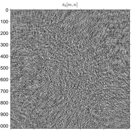
Wy ≤ ∆y. Let ¯s[m, n] (m, n∈ Z) denote the complex value of the (m, n)th SLM
pixel. (In this section, we place no restriction on the values that ¯s[m, n] can take. We assume that each ¯s[m, n] can be adjusted to any complex number.) When viewed as a discrete function of m and n, ¯s[m, n] denotes the 2D complex-valued


![Figure 3.11: Three level SLM pattern for the real part. First appeared in [1].](https://thumb-eu.123doks.com/thumbv2/9libnet/6016548.126925/85.892.190.705.350.869/figure-level-slm-pattern-real-appeared.webp)