Non-radiative resonance energy transfer in
bi-polymer nanoparticles of fluorescent conjugated
polymers
Ilkem Ozge Ozel,1,4,5 Tuncay Ozel,1,4,5, Hilmi Volkan Demir,1,3,4,5 and Donus Tuncel2,4* 1Department of Physics, Bilkent University, TR-06800, Ankara, Turkey
2Department of Chemistry, Bilkent University, TR-06800, Ankara, Turkey
3Department of Electrical and Electronics Engineering, Bilkent University, TR-06800, Ankara, Turkey 4Nanotechnology Research Center, Bilkent University, TR-06800, Ankara, Turkey 5Institute of Materials Science and Nanotechnology, Bilkent University, TR-06800, Ankara, Turkey
Abstract: This work demonstrates the comparative studies of non-radiative resonance energy transfer in bi-polymer nanoparticles based on fluorescent conjugated polymers. For this purpose, poly[(9,9-dihexylfluorene) (PF) as a donor (D) and poly[2-methoxy-5-(2'-ethyl-hexyloxy)-1,4-phenylene vinylene] (MEH-PPV) as an acceptor (A) have been utilized, from which four different bi-polymer nanoparticle systems are designed and synthesized. Both, steady-state fluorescence spectra and time-resolved fluorescence measurements indicate varying energy transfer efficiencies from the host polymer PF to the acceptor polymer MEH-PPV depending on the D-A distances and structural properties of the nanoparticles. The first approach involves the preparation of PF and MEH-PPV nanoparticles separately and mixing them at a certain ratio. In the second approach, first PF and MEH-PPV solutions are mixed prior to nanoparticle formation and then nanoparticles are prepared from the mixture. Third and fourth approaches involve the sequential nanoparticle preparation. In the former, nanoparticles are prepared to have PF as a core and MEH-PPV as a shell. The latter is the reverse of the third in which the core is MEH-PPV and the shell is PF. The highest energy transfer efficiency recorded to be 35% is obtained from the last system, in which a PF layer is sequentially formed on MEH-PPV NPs.
©2010 Optical Society of America
OCIS codes: (000.2700) General science. References and links
1. F. Kong, Y. M. Sun, and R. K. Yuan, “Enhanced resonance energy transfer from PVK to MEH-PPV in nanoparticles,” Nanotechnology 18(26), 957–961 (2007).
2. F. Kong, X. L. Wu, G. S. Huang, R. K. Yuan, and P. K. Chu, “Tunable emission from composite polymer nanoparticles based on resonance energy transfer,” Thin Solid Films 516(18), 6287–6292 (2008).
3. B. P. Lyons, K. S. Wong, and A. P. Monkman, “Study of the energy transfer processes in polyfluorene doped with tetraphenyl porphyrin,” J. Chem. Phys. 118(10), 4707–4711 (2003).
4. A. R. Buckley, M. D. Rahn, J. Hill, J. Cabanillas-Gonzalez, A. M. Fox, and D. D. C. Bradley, “Energy transfer dynamics in polyfluorene-based polymer blends,” Chem. Phys. Lett. 339(5-6), 331–336 (2001).
5. J. R. Lakowicz, Principles of Fluorescence Spectroscopy (New York: Springer, 2006).
6. K. Brunner, J. A. E. H. van Haare, B. M. W. Langeveld-Voss, H. F. M. Schoo, J. W. Hofstraat, and A. van Dijken, “Mechanistic Study of Excitation Energy Transfer in Dye-Doped PPV Polymers,” J. Phys. Chem. B 106(27), 6834–6841 (2002).
7. A. Aneja, N. Mathur, P. K. Bhatnagar, and P. C. Mathur, “Triple-FRET Technique for Energy Transfer Between Conjugated Polymer and TAMRA Dye with Possible Applications in Medical Diagnostics,” J. Biol. Phys. 34(5), 487–493 (2008).
8. K. Tada, H. Harada, M. Onoda, H. Nakayama, and K. Yoshino, “Percolation in carrier transport in FET with dye doped conducting polymers,” Synth. Met. 102(1-3), 981 (1999).
9. J. Cabanillas-Gonzalez, A. M. Fox, J. Hill, and D. D. C. Bradley, “Model for Energy Transfer in Polymer/Dye Blends Based on Point-Surface Dipole Interaction,” Chem. Mater. 16(23), 4705–4710 (2004).
(C) 2010 OSA 18 January 2010 / Vol. 18, No. 2 / OPTICS EXPRESS 670
10. J. Zheng, and T. M. Swager, “Biotinylated poly(p-phenylene ethynylene): unexpected energy transfer results in the detection of biological analytes,” Chem. Comm. 2798–2799 (2004).
11. Y.-Y. Noh, C.-L. Lee, J.-J. Kim, and K. Yase, “Energy transfer and device performance in phosphorescent dye doped polymer light emitting diodes,” J. Chem. Phys. 118(6), 2853–2864 (2003).
12. S.-K. Hong, K. H. Yeon, and S. W. Nam, “Size-dependent electronic energy relaxation in a semiconductor nanocrystal in the strong confinement limit,” Physica E 31(1), 48–52 (2006).
13. H. V. Demir, S. Nizamoglu, T. Ozel, E. Mutlugun, I. O. Huyal, E. Sari, E. Holder, and N. Tian, “White light generation tuned by dual hybridization of nanocrystals and conjugated polymers,” N. J. Phys. 9, 1367–1380 (2007).
14. J. H. Park, J. Y. Kim, B. D. Chin, Y. C. Kim, J. K. Kim, and O. O. Park, J. KyeongKim, and O. O. Park, “White emission from polymer/quantum dot ternary nanocomposites by incomplete energy transfer,” Nanotechnology 15(9), 1217–1220 (2004).
15. N. Cicek, S. Nizamoglu, T. Özel, E. Mutlugun, D. U. Karatay, V. Lesnyak, T. Otto, N. Gaponik, A. Eychmüller, and H. V. Demir, “Structural tuning of color chromaticity through nonradiative energy transfer by interspacing CdTe nanocrystal monolayers,” Appl. Phys. Lett. 94(6), 061105 (2009).
16. S. Saini, S. Bhowmick, V. B. Shenoy, and B. Bagchi, “Rate of excitation energy transfer between fluorescent dyes and nanoparticles,” J. Photochem. Photobiol. Chem. 190(2-3), 335–341 (2007).
17. C. Wu, H. Peng, Y. Jiang, and J. McNeill, “Energy Transfer Mediated Fluorescence from Blended Conjugated Polymer Nanoparticles,” J. Phys. Chem. B 110(29), 14148–14154 (2006).
18. T. Kietzke, D. Neher, K. Landfester, R. Montenegro, R. Günter, and U. Scherf, “Novel approaches to polymer blends based on polymer nanoparticles,” Nat. Mater. 2(6), 408–412 (2003).
19. T. Kietzke, D. Neher, M. Kumke, R. Montenegro, K. Landfester, and U. Scherf, “A Nanoparticle Approach To Control the Phase Separation in Polyfluorene Photovoltaic Devices,” Macromolecules 37(13), 4882–4890 (2004).
20. C. Wu, Y. Zheng, C. Syzmanski, and J. McNeill, “Energy Transfer in a Nanoscale Multichromophoric System: Fluorescent Dye-Doped Conjugated Polymer Nanoparticles,” J. Phys. Chem. C Nanomater, Interfaces 112, 1772–1781 (2008).
21. S. Grigalevicius, M. Forster, S. Ellinger, K. Landfester, and U. Scherf, “Excitation Energy Transfer from Semi-Conducting Polymer Nanoparticles to Surface-Bound Fluorescent Dyes,” Macromol. Rapid Commun. 27(3), 200–202 (2006).
22. I. O. Huyal, T. Ozel, D. Tuncel, and H. V. Demir, “Quantum efficiency enhancement in film by making nanoparticles of polyfluorene,” Opt. Express 16(17), 13391–13397 (2008).
23. N. Kurokawa, H. Yoshikawa, N. Hirota, K. Hyodo, and H. Mashuhara, “Size-Dependent Spectroscopic Properties and Thermochromic Behavior in Poly(substituted thiophene) Nanoparticles,” ChemPhysChem 5(10), 1609–1615 (2004).
24. C. Syzmanski, C. Wu, J. Hooper, M. A. Salazar, A. Perdomo, A. Dukes, and J. McNeill, “Single Molecule Nanoparticles of the Conjugated Polymer MEH−PPV, Preparation and Characterization by Near-Field Scanning Optical Microscopy,” J. Phys. Chem. B 109(18), 8543–8546 (2005).
25. F. Wang, M.-Y. Han, K. Y. Mya, Y. Wang, and Y.-H. Lai, “Aggregation-Driven Growth of Size-Tunable Organic Nanoparticles Using Electronically Altered Conjugated Polymers,” J. Am. Chem. Soc. 127(29), 10350– 10355 (2005).
26. H. Kasai, H. S. Nalwa, S. Okada, H. Matsuda, N. Minami, A. Kakuta, K. Ono, A. Mukoh, and H. Nakanishi, “A Novel Preparation Method of Organic Microcrystals,” Jpn. J. Appl. Phys. 31(Part 2, No. 8A), L1132–L1134 (1992).
27. H. Kasai, H. Kamatani, S. Okada, H. Oikawa, H. Matsuda, and H. Nakanishi, “Size-Dependent Colors and Luminescences of Organic Microcrystals,” Jpn. J. Appl. Phys. 35(Part 2, No. 2B), L221–L223 (1996). 28. C. Wu, B. Bull, C. Syzmanski, K. Christensen, and J. McNeill, “Multicolor Conjugated Polymer Dots for
Biological Fluorescence Imaging,” J. ACS NANO 2(11), 2415–2423 (2008).
29. A. Kawski, J. Kaminski, and E. Kuten, “Quenching of photoluminescence of solutions by electronic excitation transfer,” J. Phys. B 4(4), 609–620 (1971).
30. A. Kawski, E. Kuten, and J. Kaminski, “Fluorescence quenching and nonradiative energy transfer in solutions,” J. Phys. B 6(9), 1907–1916 (1973).
31. C. J. Murphy, “Biosensors: Plasmons spring into action,” Nat. Mater. 6(4), 259–260 (2007). 1. Introduction
Exhibiting superior optical properties, polyfluorenes have emerged as one of the most promising conjugated polymers for use in solid-state lighting applications. As blue emitters, polyfluorenes retain very high quantum efficiencies. This can be useful for efficient energy transfer from polyfluorene acting as the donor to any lower energy acceptor molecule. Various studies have been carried out to analyze the energy transfer mechanisms, which can be radiative or non-radiative [1–4]. Radiative energy transfer involves the emission of a photon by the highly energetic polymer and subsequent re-absorption by the acceptor. The non-radiative energy transfer also called resonance energy transfer (RET), on the other hand, is a more efficient and rapid process, which does not involve emission of light from the donor.
(C) 2010 OSA 18 January 2010 / Vol. 18, No. 2 / OPTICS EXPRESS 671
This process is aided by the coupled dipole-dipole interactions of the donor and acceptor molecules [5]. Since the efficiency of radiative energy transfer is relatively low compared to RET efficiency, the latter mechanism will be of major concern in our study though Förster theory is not necessarily the only mechanism valid in our systems under investigation. Hybrid systems consisting of donor polymer molecules and acceptor dye molecules for energy transfer have been thoroughly studied since several years [6–13]. These systems are mainly mixtures of donor and acceptor solutions, so that energy transfer takes place among random mixing proximal donor and acceptor molecules [3,4]. Single donor-acceptor distances cannot be identified for such solutions, for which more complex calculations including the averaging of transfer rates are then required. Though, if incidentally donor and acceptor molecules come into close vicinity (at comparable distances with the Förster radius), this process turns out to be efficient; the efficiency of the transfer mechanism is mainly limited by the random distribution of donor and acceptor molecules throughout the solution. A second approach is the energy transfer obtained from hybrid polymer solution-nanocrystal systems, in which nanocrystals are embedded in the energy donating polymer matrix [12–14]. The third and last approach, which has been recently developed for several materials, is the combination of donor nanoparticles and acceptor nanoparticles in form of physical mixtures. Nanostructures used for such purposes are mixtures of NCs [15], two metal NPs [16], polymer nanoparticle blends prepared via the reprecipitation or the mini-emulsion methods either by mixing of polymer solutions and then forming NPs or first the formation of polymer NPs and then mixing of NP dispersions [1,2,17–19]. Also, recently blends of polymers and dyes have been described by McNeill and associates. This group reported the fluorescence properties and effects of energy diffusion and energy transfer in polyfluorene based nanoparticles, which are doped with various fluorescent dyes [20]. Another study conducted by Scherf and associates involves the excitation energy transfer from polymer nanoparticles prepared via the mini-emulsion method to surface-bound Rhodamine 6G [21].
Being very similar to the first approach in terms of the proximities of the donor and acceptor species except for the polymer NPs which are comprised of two different polymers or nano-composites containing both polymer and dye within the same structure, neither of those methods allows for the flexibility of construction of different architectures, which may enable the opportunity to search for the most efficient and stable structure.
Here we report novel dual-emitting bi-polymer nanoparticles prepared by the reprecipitation method. Especially, sequentially formed core-shell nanoparticles are of particular interest owing to their enhanced energy transfer efficiencies. Optical measurement results strongly support the formation of such sequential nanoparticles, when compared to the optical behavior of other polymer nanoparticles. To elucidate energy transfer mechanisms among the blue-emitting conjugated polymer derivative of polyfluorene (PF) and the red-emitting PPV-derivative MEH-PPV, we designed four different nanoparticle systems.
In System 1, the nanoparticles of PF and MEH-PPV are prepared separately and mixed after nanoparticle formation. System 2 involved the formation of nanoparticles from a mixture of PF and MEH-PPV solutions, so that polymer chains of each polymer were randomly distributed in each nanoparticle. For Systems 3 and 4, novel assemblies of sequentially formed nanoparticles were obtained. The former one is composed of PF inside and is surrounded by MEH-PPV outside, while the latter is the reverse structure, i.e., MEH-PPV forms the inner structure and PF the outer structure of the nanoparticles.
2. Results and discussion
2.1. Synthesis of nanoparticles
To study the energy transfer among fluorescent nanoparticles and their efficiencies, four different systems containing PF and MEH-PPV are designed and synthesized as depicted in Fig. 1. PF (poly[9,9-dihexyl-9H-fluorene]) was synthesized by the Suzuki coupling of 2,7-dibromo-9,9-dihexyl-9H-fluorene with 9,9-dihexylfluorene-2,7-bis(trimethyleneborate) in
(C) 2010 OSA 18 January 2010 / Vol. 18, No. 2 / OPTICS EXPRESS 672
64% yield. MEH-PPV (poly[2-methoxy-5-(2'-ethyl-hexyloxy)-1,4-phenylene vinylene]) was purchased from Sigma-Aldrich with an average Mn of 70,000-100,000 and was used as
received. Nanoparticles were prepared using the reprecipitation method as described previously [20,22–28]. In this method, the fluorescent conjugated polymer is dissolved in a good solvent (such as THF) and the solution is added into a large amount of poor solvent (usually water) under sonication. The polymer chains are folded in a spherical shape due to hydrophobic effect in a poor solvent to form nanoparticles. To stabilize these nanoparticles and prevent them from dissolving once again in THF, the solvent is evaporated shortly. The size of the nanoparticles can be tuned by varying the concentration of polymer solution and the amount of poor solvent. Using this method, it is possible to obtain a dispersion of nanoparticles in water as small as 5-10 nm.
All polymer solutions and nanoparticle dispersions were prepared by taking the same amounts from the stock PF and MEH-PPV solutions for each set containing a total amount of 32 mL as liquid. The constant concentration of PF used in all sets is 9.0 x 10⁻³ mM. To obtain two different sets for comparison, the concentration of MEH-PPV was only varied, which will be denoted by a and b. Based on the molecular weight of the repeating units, these concentrations are calculated to be 4.6 x 10⁻³ mM and 18.2 x 10⁻³ mM, respectively. In total, from four nanoparticle systems we prepared eight dispersions for each MEH-PPV concentration a and b. The preparation of nanoparticles in these four systems is described below:
2.1.1. System 1
Nanoparticles of PF and MEH-PPV polymers are prepared separately from different concentrations of polymer solutions (with PF at constant concentration, while MEH-PPV is prepared at concentrations a and b) and are then mixed at a 1:1 ratio to obtain the mixed-nanoparticle system. The mixtures are denoted by (PF NP + MEH-PPVa NP) and (PF NP + MEH-PPVb NP), respectively.
2.1.2. System 2
The solutions of PF and MEH-PPV are mixed at two ratios and from this solution nanoparticles are prepared using the reprecipitation method. The resulting nanoparticle mixtures are denoted by (PF + MEH-PPVa) mixed NP and (PF + MEH-PPVb) mixed NP, respectively.
2.1.3. System 3
PF nanoparticles are prepared first as core and MEH-PPV solution is added sequentially to the preformed nanoparticles. With this method we expect to obtain sequentially formed core-shell nanoparticles in which PF is the core and MEH-PPV is the shell as the driving force here is the nucleation effect of the polymers. For this system we use the following representation, (PF/MEH-PPVa) sequential NP and (PF/MEH-PPVb) sequential NP.
2.1.4. System 4
It is similar to System 3. However, in this system MEH-PPV constructs the core and PF the shell. These nanoparticles are denoted by PPVa/PF) sequential NP and (MEH-PPVb/PF) sequential NP.
(C) 2010 OSA 18 January 2010 / Vol. 18, No. 2 / OPTICS EXPRESS 673
Fig. 1. Schematic representation of the proposed nanostructures for polymer nanoparticles formed from PF and PPV via the reprecipitation method. (a) System 1: (PF NP + MEH-PPV NP), (b) System 2: (PF + MEH-MEH-PPV) mixed NPs, (c) System 3: (PF/MEH-MEH-PPV) sequential NPs, and (d) System 4: (MEH-PPV/PF) sequential NPs.
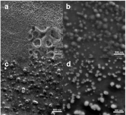
Though an exact structural determination of each nanoparticle system could not be made, SEM characterization was performed for the films of PF solution, individual PF NP dispersion, MEH-PPVa NP dispersion and (MEH-PPVa/PF) sequential NP dispersion as shown in Fig. 2 to give an idea about the sizes of the nanoparticles and show that the sequentially formed nanoparticles preserve their shape.
Fig. 2. SEM micrographs of films prepared from (a) PF solution, (b) PF NP dispersion (c) MEH-PPVa NP dispersion, and (d) (MEH-PPVa/PF) sequential NP dispersion. The last image is taken with a tilt angle of 15°.
(C) 2010 OSA 18 January 2010 / Vol. 18, No. 2 / OPTICS EXPRESS 674
2.2. Investigation of photophysical properties of nanoparticles
For the investigation of the photophysical properties of our four nanosystems, we run additional control experiments for solutions of PF and MEH-PPV at concentrations a and b for MEH-PPV. To track changes in energy transfer efficiencies upon formation of various nanoarchitectures, we make use of steady-state and time-resolved fluorescence spectroscopy methods.
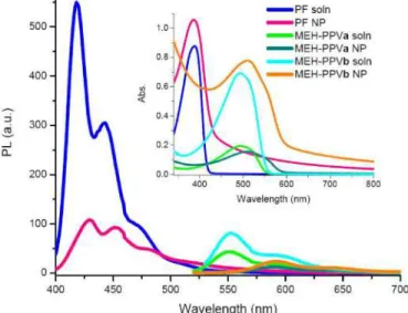
Collapse of polymer chains into nanoscale spherical particles results in red-shifted emission spectra by over 10 to 41 nm depending on the particle size and type of polymer being folded, as we described recently [22]. Figure 3 shows the changes in peak position of PF and MEH-PPV from their solution to nanoparticle dispersion states. Correspondingly, the inset demonstrates the absorption spectra of solutions and their polymer nanoparticle dispersions.
Fig. 3. Onset: Emission spectra of PF solution and its corresponding PF NP dispersion, MEH-PPVa solution and its corresponding MEH-MEH-PPVa NP dispersion, and MEH-PPVb solution and its corresponding MEH-PPVb NP dispersion. Inset: Absorption spectra of PF solution and PF NP dispersion, MEH-PPVa solution and MEH-PPVa NP dispersion, and MEH-PPVb solution and MEH-PPVb NP dispersion.
The emission red-shifts from 418 nm to 429 nm when PF NPs are prepared from the PF solution (at its given concentration). We observe an even more pronounced shift for MEH-PPVa NPs changing from 551 nm to 589 nm and from 552 nm to 592 nm for MEH-PPVb NPs. The emission spectra of only PF NPs and MEH-PPV NPs will be used as reference curves to determine the resulting nanostructure and the energy transfer mechanism, as they provide evidence on how compact NPs are formed and how strongly they interact with each other.
Another measure of the transfer mechanisms is the lifetime of the donating and accepting species. All decay curves could be fitted with two exponentials. For comparison of different systems average intensity weighted lifetimes are under consideration. The average lifetimes are evaluated to be 0.01 ns for PF solution and 0.26 ns for PF NP dispersion. They are 0.32 ns for MEH-PPVa solution, 0.33 ns for MEH-PPVb solution, 0.51 ns for MEH-PPVa NP dispersion and 0.39 ns MEH-PPVb NP dispersion. Similar to the trend observed for spectral shifts of polymer species when transformed from the solution state to the dispersion state, we observe an increase in the decay times of the dispersions. This may be due to a retarded emission, which is caused by stacking and kinking of polymer chains within the boundaries of the nanoparticles; this in turn creates a shielded environment.
(C) 2010 OSA 18 January 2010 / Vol. 18, No. 2 / OPTICS EXPRESS 675
2.2.1. Control experiments
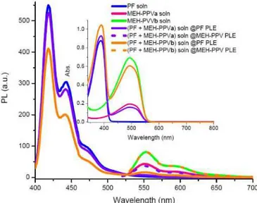
Figure 4 illustrates the emission spectra of only PF solution, only MEH-PPV solution and also their mixtures.
Fig. 4. Onset: Emission spectra of solutions of PF, PPVa, PPVb, (PF + MEH-PPVa) and (PF + MEH-PPVb) at absorption maximum of PF (solid) and absorption maximum of MEH-PPV (dotted). Inset: Absorption spectra of PF, MEH-PPVa, MEH-PPVb, (PF + MEH-PPVa), and (PF + MEH-PPVb) solutions.
In the mixture of PF and MEH-PPVa we obtain no emission at around 551 nm at the photoluminescence excitation (PLE) of PF. Lifetimes of PF and MEH-PPVa in solution at 418 nm and 551 nm are found to be 0.01 ns and 0.21 ns. The lack of energy transfer can also be tracked from almost no quenching of the PF peak.
Dealing here with a solution of donor-acceptor pairs which are free to move randomly in solution and thus are not separated by a fixed distance (for example as in the case of control experiments and System 1), it is not appropriate to calculate the energy transfer efficiency by directly using the commonly known expressions (1) and (2),
1 DA D
τ
η= − τ (1)
where τDAand τDdenote the average weighted lifetimes of the donor in the presence and
absence of acceptor, respectively, and
1 DA D F
F
η= − (2)
whereFDA andFD denote the peak photoluminescence intensity level of the donor in the
presence and absence of acceptor. However, it is worth noting that these equations can be safely applied for Systems 2, 3 and 4, where the distance between the donor and acceptor is fixed [5]. The Förster radius of this solution is calculated to be 4.4 nm according to
2 6 4 0 5 4 0 9000(ln10) ( ) ( ) 128 D D A Q R F d Nn κ λ ε λ λ λ π ∞ =
∫
(3)where QD is the quantum yield of the donor (taken to be 80% in solution), κ is the orientation factor (taken to be 2/3 for randomly distributed orientation), N is Avogadro’s
(C) 2010 OSA 18 January 2010 / Vol. 18, No. 2 / OPTICS EXPRESS 676
number, n is the refractive index (taken to be approximately 1.4 for THF solution), FD( )λ is the experimentally measured photoluminescence spectrum of the donor and ε λA( ) is the extinction coefficient of the acceptor. To estimate the transfer efficiency for this case, we calculate the relative steady-state quantum yield of the donor by
1/ 2 2 1 exp( )[1 ( )] DA D F erf F = −π γ γ − γ (4) where 2 1/ 2 0 2 ( ) exp( ) erf x dx γ γ π =
∫
− with A 0 A C Cγ = and CA being the acceptor concentration,
and 0 3/ 2 3 0 3000 2 A C NR π
= (in moles/liter) for the case of control experiments and System 1 with varying D-A distances [5,29,30]. Using these expressions the transfer efficiency is estimated to be 0.15%. For an increased amount of acceptor molecules lifetimes are found to be 0.01 ns and 0.36 ns at 418 nm and 552 nm, respectively. This is a result of reduced donor-acceptor molecule distances as donor molecules are surrounded by a larger amount of acceptor molecules with increased MEH-PPV concentration. The resulting transfer efficiency of this system is 0.61%. However, still we are far off the range at which donor and acceptor molecules can interact efficiently. Thus, the design of new NP systems embedding both polymer species becomes a crucial step for the realization of efficient energy transfer, which could be especially useful for white light applications.
2.2.2. System 1
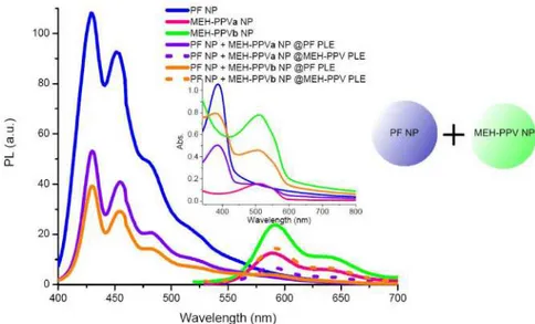
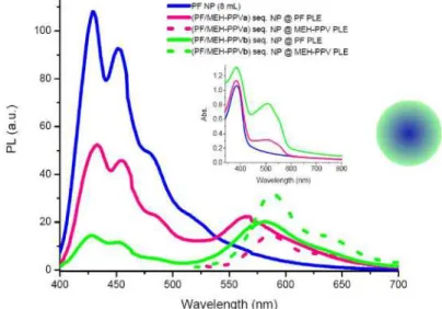
In System 1, in which separately formed nanoparticles of PF and MEH-PPV are mixed in 1:1 ratio after nanoparticle formation, we observe that similar to the previous case the emission peak positions do not change with respect to their original states. The photoluminescence (PL) curves exhibit two peaks at 429 nm and 589 for the (PF NP + MEH-PPVa NP) dispersion and 429 nm and 592 nm for the (PF NP + MEH-PPVb NP) dispersion (Fig. 5). In terms of proximities and as a result, the interaction abilities of the donor and acceptor species these formerly mentioned two systems are similar to each other. Though in this system the distances between donor and acceptor should be seen as doubled, since the donor and acceptor concentration are reduced to half the initial concentration. This becomes also evident from the very low energy transfer efficiencies, which are calculated to be 0.04% for (PF NP + MEH-PPVa NP) and 0.21% for (PF NP + MEH-PPVb NP. The energy transfer efficiencies are not calculated from lifetimes of the donor with and without donor using (1), as there are no fixed D-A distances similar to the solution of PF and MEH-PPV considered above. For this system we use (3) to calculate the transfer efficiencies. The estimated D-A distances are found to be 13.3 nm and 10.8 nm, respectively.
The concentration of each species in the mixtures of PF NPs and MEH-PPV NPs given in Fig. 5 is reduced to half the initial value, since the individual nanoparticle dispersions are mixed in a 1:1 ratio. In order to obtain an estimate of the reference donor emission without acceptor as well as acceptor emission without donor, one may consider the curves given in Fig. 5 of PF NP and MEH-PPV NP multiplied by 0.5.
The relatively high absorbance of MEH-PPVb NPs at 350-400 nm overlapping with the absorption band of PF nanoparticles is related with scattering effects for large nanoparticles. The excitation spectrum of MEH-PPVb NPs reveals little excitation of MEH-PPV moeties within this wavelength range as was also verified by comparing the maximum peak intensities of MEH-PPV upon excitation at 380 nm and 520 nm. The ratio was calculated to be 0.13, small enough to neglect the emission caused by the excitation light source at 380 nm.
(C) 2010 OSA 18 January 2010 / Vol. 18, No. 2 / OPTICS EXPRESS 677
Fig. 5. Onset: Emission spectra of PF NP, MEH-PPVa NP, MEH-PPVb NP dispersions and their corresponding mixtures in a 1:1 ratio as (PF NP + PPVa NP) and (PF NP + MEH-PPVb NP) at absorption maximum of PF (solid) and MEH-PPV (dotted), respectively. The concentration of each species in the NP mixtures is reduced by a factor of two due to mixing. Inset: Absorption spectra of PF NP, MEH-PPVa NP, MEH-PPVb NP dispersions and their mixtures in a 1:1 ratio, (PF NP + MEH-PPVa NP) and (PF NP + MEH-PPVb NP).
2.2.3. System 2
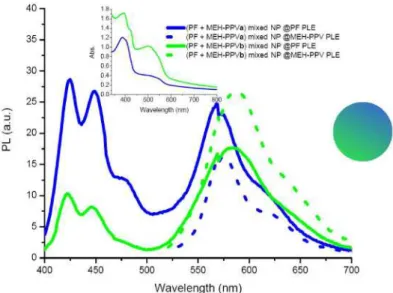
In the second bi-polymer NP system, NPs were formed by mixing solutions of PF and MEH-PPV in two different PF to MEH-MEH-PPV ratios and pouring those into 32 mL deionized and sonicated water. This way, we achieve the formation of NPs which contain both species in one NP. Evidence to this is given by the spectral changes as given in Fig. 6, which we observe with respect to the peaks of only PF and MEH-PPV NPs. For the (PF + MEH-PPVa) mixed NPs, the peak of PF appears at 425 nm and that of MEH-PPV at 569 nm. However, when the bi-polymer system is excited at approximately 520 nm to give maximum emission of MEH-PPV only, we observe an emission at 577 nm.
(C) 2010 OSA 18 January 2010 / Vol. 18, No. 2 / OPTICS EXPRESS 678
Fig. 6. Onset: Emission spectra of (PF + MEH-PPVa) and (PF + MEH-PPVb) mixed NPs at absorption maximum of PF (solid) and MEH-PPV (dotted). Inset: Corresponding absorption spectra of (PF + MEH-PPV) mixed NPs.
The blue-shifted emission at 577 nm of our mixed NPs at PLE of MEH-PPV with respect to the peak observed at 589 nm for only MEH-PPV NPs, shows that the intrinsic nature of our NPs has changed. The fact that MEH-PPV chains are randomly separated by other PF chains reduces the effective conjugation length of the polymer chains, while on the other hand the competing intra- and interchain forces resulting from chain folding and stacking have still a red-shifting effect on the emission. The emission at 569 nm of the MEH-PPV species in the bi-polymer system, when we use a pump light at 380 nm so that PF is excited, is probably caused by increased donor-acceptor interactions. The increased oscillating dipole-dipole interactions upon excitation of PF create a nearby electric field, which does not allow the acceptor molecules to find their minima for relaxation so that MEH-PPV moieties emit at higher energies [31]. In this system, as we do not really have a corresponding reference for the PF emission without acceptor molecules, we can only speculate on the efficiency of energy transfer and quenching of the PF peak. Time-resolved measurements turn out to give average lifetimes of 0.21 ns and 0.69 ns at 425 nm and 569 nm, respectively. Using (1), the transfer efficiency for (PF + MEH-PPVa) mixed NPs is calculated to be 19%, while this value is only an approximation since the lifetime of only PF NPs is used for τD. However, it is certainly clear that this approach is more efficient when compared to System 1 and the mixtures in solution. For (PF + MEH-PPVb) mixed NPs the efficiency is calculated to be 15% as structural changes are even more compared to (PF + MEH-PPVa) mixed NPs. Though an increased efficiency is expected due to an increased amount of acceptor molecules, the fact that the total volume of THF solution injected into sonicated water is too much strongly indicates the failure of properly formed nanoparticles. The mixed NPs from (PF + MEH-PPVb) emit at 422 nm and 583 nm when excited at maximum absorption of PF, and emit at 588 nm at maximum absorption of MEH-PPV.
2.2.4. Systems 3 and 4
In our next approach, we analyze the novel nanoparticles, which have been prepared in a sequential manner. By this method, we are able to construct the inside of NPs from one polymer while the surrounding layer is made of the other polymer. Our aim is to achieve pure material properties on each polymer domain, while keeping them at distances comparable with the Förster radius. Emission and corresponding absorption spectra of (PF/MEH-PPV) sequential NPs are given in Fig. 7. At the PLE of MEH-PPV the emission peaks are at 587 nm
(C) 2010 OSA 18 January 2010 / Vol. 18, No. 2 / OPTICS EXPRESS 679
and 589 nm for concentrations a and b, which almost perfectly matches with emission peaks of only MEH-PPVa and MEH-PPVb NPs at 589 nm and 592 nm, respectively. Little changes result from the fact that MEH-PPV is now surrounding the inner core consisting of PF, thus forming a looser structure as a shell. Excitation of the (PF/MEH-PPV) sequential NPs at the PLE of PF results on the other hand in a blue-shifted MEH-PPV emission by 21 to 7 nm for concentrations a and b with respect to the emission of MEH-PPV at PLE of MEH-PPV. This effect was already observed above for the other systems. When MEH-PPV is sequentially added to the PF NPs, the PF emission is quenched. The average lifetimes of (PF/MEH-PPVa) sequential NPs are fitted by two exponentials to be 0.20 ns at 429 nm and 1.22 ns at 566 nm, while we measure 0.20 ns and 0.67 ns for (PF/MEH-PPVb) sequential NPs at 425 nm and 582 nm, respectively. Time-resolved spectra for individual PF and MEH-PPVa NPs at 429 nm and 589 nm and (PF/MEH-PPVa) sequential NPs at 429 nm and 566 nm are given in Fig. 8. The energy transfer efficiency for the former dispersion is calculated to be 23%, using (1). Since the whole PF domain is surrounded by a MEH-PPV domain, MEH-PPV exhibits almost the same emission characteristics in the structure when it is excited at its own maximum absorption wavelength in both cases a and b. At the maximum absorption of PF, we observe that especially for the (PF/MEH-PPVa) sequential NP system the emission of MEH-PPV is much more blue-shifted (21 nm) with respect to the PPV emission at the PLE of MEH-PPV in that corresponding system, than in all other cases. There are two reasons for this observation. The first reason is that there exists a strong interaction between donor and acceptor molecules, which results in the decay of acceptor molecules at
Fig. 7. Onset: Emission spectra of PF NPs, (PF/MEH-PPVa) sequential NPs at absorption maximum of PF (solid) and MEH-PPV (dotted), and (PF/MEH-PPVb) sequential NPs at absorption maximum of PF (solid) and MEH-PPV (dotted) Inset: Absorption spectra of PF NPs and (PF/MEH-PPV) sequential NPs.
shorter wavelengths as has been observed also above for the second structure. And the second reason for the large shift when compared specifically to the b sample is that in the former structure there is a thinner layer of MEH-PPV so that all acceptor molecules strongly interact with the donor molecules. Evidence for the fact that MEH-PPV molecules really mostly surround the PF NPs in dispersion a, but do not form separate MEH-PPV NPs is the emission peak of MEH-PPV at 587 nm instead of 589 nm for MEH-PPV when we excite the system at maximum absorption of MEH-PPV. An even stronger evidence however is the pronounced
(C) 2010 OSA 18 January 2010 / Vol. 18, No. 2 / OPTICS EXPRESS 680
Fig. 8. Biexponentially fitted decay curves of PF NPs at 429 nm (0.26 ns), MEH-PPVa NPs at 589 nm (0.51 ns) and (PF/MEH-PPVa) sequential NPs at 429 nm (0.20 ns) and 566 nm (1.22 ns). Reported lifetimes are average intensity weighted values and decay fit parameter “R” ranges from 0.8 to 1.2.
blue-shifted emission of PPV at the PLE of PF with respect to the emission of MEH-PVP at PLE of MEH-PPV. This is not exactly the case for the latter dispersion, as MEH-PPV blue-shifts merely 7 nm. This indicates that there is a reduced interaction between PF and MEH-PPV as more MEH-PPV chains have formed individual NPs.
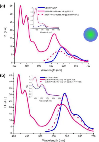
Finally, there is the last nanoparticle system as shown in Fig. 9, which is very similar to the previous one, except that MEH-PPV forms the inner structure while the PF layer surrounding it, is sequentially formed later. For this system as in the second structure with mixed nanoparticles, we also do not have a reference initial PF emission spectrum without acceptor molecules, so that it is not possible to directly calculate the energy transfer efficiency from the quenching of the donor emission.
(C) 2010 OSA 18 January 2010 / Vol. 18, No. 2 / OPTICS EXPRESS 681
Fig. 9. a) Onset: Emission spectra of MEH-PPV NPs, (MEH-PPVa/PF) sequential NPs at absorption maximum of PF (solid) and PPV (dotted). Inset: Absorption spectra of MEH-PPV NPa and (MEH-MEH-PPVa/PF) sequential NPs, b) Onset: Emission spectra of MEH-MEH-PPVb NPs, (MEH-PPVb/PF) sequential NPs at absorption maximum of PF (solid) and MEH-PPV (dotted). Inset: Absorption spectra of MEH-PPVb NP and (MEH-PPVb/PF) sequential NPs.
An important fact about the donor emissions in both sets is that though more quenching of donor emission is expected for (MEH-PPVb/PF) sequential NPs due to increased acceptor concentration, this is not the case. This is probably a morphological effect resulting from higher photoluminescence efficiency of the thinner PF layer formed around MEH-PPVb, while on the contrary the thicker PF layer around MEH-PPVa, subject to serious inter- and intramolecular interactions, leads to reduced emission intensity of PF chains which are not involved in the non-radiative energy transfer mechanism. The elusory higher intensity of MEH-PPV emission in (MEH-PPVb/PF) sequential NPs comes from the fact that the tail of PF emission is higher in intensity when compared to (MEH-PPVa/PF) sequential NPs. Since this time PF forms the outer structure of our sequentially formed nanoparticles, losses due to reflection or several other non-radiative processes are not of major concern, so that the expected energy transfer efficiency of this approach might be higher than calculated for the reverse structure above. Indeed, the calculated transfer efficiency for (MEH-PPVa/PF)
(C) 2010 OSA 18 January 2010 / Vol. 18, No. 2 / OPTICS EXPRESS 682
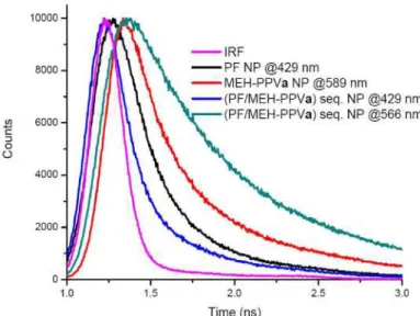
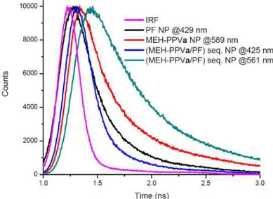
sequential NPs is 35%, which is the highest calculated energy transfer efficiency of all structures. This makes this structure a promising candidate in terms of efficiency for use in energy transfer in dual-color emitting systems. Time-resolved measurements show 0.17 ns at 425 nm and 0.90 ns at 561 nm for sample a. Decay curves for individual PF and MEH-PPVa NPs at 429 nm and 589 nm and (MEH-PPVa/PF) sequential NPs at 425 nm and 561 nm are given in Fig. 10.
Fig. 10. Biexponentially fitted decay curves of PF NPs at 429 nm (0.26 ns), MEH-PPVa NPs at 589 nm (0.51 ns) and (MEH-PPVa/PF) sequential NPs at 425 nm (0.17 ns) and 561 nm (0.90 ns). Reported lifetimes are average intensity weighted values and decay fit parameter “R” ranges from 0.8 to 1.1.
Similar arguments as were discussed for (PF/MEH-PPV) sequential nanoparticles hold for the formation of (MEH-PPV/PF) sequential NPs. Evidence for the fact that we formed bi-polymer nanoparticles, but not separate PF and MEH-PPV NPs, is the emission peak position of the outer polymer domain, in this case the PF layer. For sample a as the PF layer is thicker we observe an emission at 425 nm, which shows that PF did not form separate NPs emitting normally at 429 nm. PF in sample b on the other hand emits at 419 nm, which shows really how thin the PF layer on the inner MEH-PPV domain is, so that its emission characteristics have almost not changed in comparison to the PF solution [22]. A second evidence for the verification of the resulting structure is also the slightly blue-shifting MEH-PPV emission at PLE of PF, which shows that PF and MEH-PPV domains are in very close proximity.
3. Conclusion
We successfully showed differences in optical behavior of four differently designed polymer nanosystems. Resonance energy transfer efficiencies of these systems were calculated to explicitly discover the most useful structure. The solution mixtures of PF and MEH-PPV as well as System 1, in which we have a mixture of individual PF NPs and MEH-PPV NPs, exhibit almost the same low values of energy transfer efficiencies. In principle both systems have large D-A separations, which in turn results in low transfer efficiency values. The systems prepared by keeping donor and acceptor molecules within a closer distance, show significantly improved efficiencies, around 10 times higher or more. The highest energy transfer efficiency was recorded for the (MEH-PPVa/PF) sequential NP system.
The studies of energy transfer in the four systems using static and dynamic fluorescent spectroscopy reveal that the nanoparticles of the first approach show no acceptor emission. The nanoparticles of the second approach show a considerably stronger emission for the acceptor while donor emission is suppressed. The Förster radius for the system composed of
(C) 2010 OSA 18 January 2010 / Vol. 18, No. 2 / OPTICS EXPRESS 683
individual PF nanoparticles and MEH-PPV nanoparticles has been calculated to be 3.6 nm and 3.9 nm, for two different MEH-PPV concentrations a and b. The sequential hybrid nanoparticles prepared in the third and fourth approaches show remarkably higher energy transfer efficiencies as high as 35%.
Acknowledgments
This work is supported by EU MOON, EU NOE PHOREMOST and TUBITAK 104E114, 106E020, 107E088, 107E297, 109E002, 105E065, and 105E066. H.V.D. also acknowledges additional support from Turkish Academy of Sciences (TUBA GEBIP) and European Science Foundation (ESF-EURYI), and I.O.O.., from TUBITAK.
(C) 2010 OSA 18 January 2010 / Vol. 18, No. 2 / OPTICS EXPRESS 684