Journal of Optics A: Pure and Applied Optics
Bilayer metamaterial: analysis of left-handed
transmission and retrieval of effective medium
parameters
To cite this article: K Guven et al 2007 J. Opt. A: Pure Appl. Opt. 9 S361
View the article online for updates and enhancements.
Related content
Metamaterials with negative permeability and negative refractive index: experiments andsimulations
Ekmel Ozbay, Kaan Guven and Koray Aydin
-Super-resolution imaging by one-dimensional, microwave left-handed metamaterials with aneffective negative index
Ekmel Ozbay, Zhaofeng Li and Koray Aydin
-Chiral metamaterials: simulations and experiments
Bingnan Wang, Jiangfeng Zhou, Thomas Koschny et al.
-Recent citations
A broad-band three-dimensional isotropic left-handed metamaterial
Jia Fu Wang et al
J. Opt. A: Pure Appl. Opt. 9 (2007) S361–S365 doi:10.1088/1464-4258/9/9/S13
Bilayer metamaterial: analysis of
left-handed transmission and retrieval of
effective medium parameters
K Guven
1,2, A O Cakmak
1,3, M D Caliskan
1, T F Gundogdu
4,
M Kafesaki
4, C M Soukoulis
4,5and E Ozbay
1,2,31Nanotechnology Research Center, Bilkent University, 06800 Ankara, Turkey 2Department of Physics, Bilkent University, 06800 Ankara, Turkey
3Department of Electrical and Electronics Engineering, Bilkent University, 06800 Ankara,
Turkey
4Foundation for Research and Technology Hellas (FORTH), GR-71110 Heraklion, Crete,
Greece
5Ames Laboratory and Department of Physics, and Astronomy, Iowa State University, Ames,
IA 50011, USA
Received 31 January 2007, accepted for publication 13 April 2007
Published 23 August 2007
Online at
stacks.iop.org/JOptA/9/S361
Abstract
We report an experimental and numerical analysis of a planar metamaterial
designed for normal-to-plane propagation, and operating at microwave
frequencies. The metamaterial consists of cutwire and wire patterns, which
are arranged periodically on both sides of a dielectric layer, in the form of a
bilayer. The left-handed transmission band of the metamaterial is
demonstrated experimentally. The effective index of refraction retrieved from
the S parameters is found to be negative within this transmission band. An
independent negative refraction experiment supports the existence of the
negative index of refraction for the metamaterial.
Keywords:
metamaterial, negative index, split-ring resonator, negative
refraction
(Some figures in this article are in colour only in the electronic version)
1. Introduction
Metamaterials are artificial structures which provide a tailored electromagnetic response at the desired frequency range. This response is generated by metallic substructures which exhibit certain resonances induced by the electric and magnetic field components of the electromagnetic wave, respectively [1, 2]. By virtue of the subwavelength size of these substructures, the response of the metamaterial may be characterized by effective permittivity,ε, and permeability,μ, parameters. The unique property of the metamaterials is that the real parts ofε andμcan take simultaneously negative values, which results in a medium with negative index of refraction with unusual electromagnetic properties [3–5].
In this paper, we report the design and fabrication of a quasi-one-dimensional planar composite metamaterial (CMM) for microwave frequencies, and present an experimental and
numerical analysis of the left-handed transmission through this metamaterial. We employ a recently introduced topology for the design, where the electromagnetic wave propagates normal to the metamaterial plane (i.e. the electric and magnetic field vectors are parallel to the metamaterial plane) [6, 7]. This topology provides significant advantages over the conventional split-ring resonator (SRR)/wire based CMMs [4,8], particularly for infrared and optical operation frequencies, where the fabrication of the conventional design proved to be highly challenging [9–14]. Thus far, metamaterials fabricated for the terahertz range are restricted to be single layer due to the difficulties of the multilayer process. The highest frequency bulk (i.e. multilayer) CMM, where the electromagnetic field can propagate truly within the medium, was reported for 100 GHz [15]. There are a number of reports in the literature which employ various designs based on the normal-to-plane propagation topology, with successful
K Guven et al
implementations at the infrared regime [16–21]. Yet, there is still need for experimental study of the transmission properties and the negative refraction of multilayer bulk metamaterials in the new topology.
In this work, we address this need, and report the direct observation of the left-handed transmission band of a multilayer CMM under normal-to-plane propagation. The identification of the left-handed transmission band is done by the same method applied for the conventional SRR/wire-based CMM, reported previously [8]. The negative refraction phenomenon of electromagnetic waves for oblique incidence angles is also observed. In addition, we employ the retrieval procedure for obtaining the effective medium parameters of the metamaterial [22, 23] and confirm the double-negative (ε < 0, μ < 0) behaviour within the relevant transmission frequency band.
The paper is organized as follows. In section 2, we describe the design and fabrication of the metamaterial. Section 3presents the measured and simulated transmission spectra. The negative refraction experiment performed with this structure is presented in section 4. In section 5, we discuss the retrieval of effective medium parameters. Section6 summarizes the results and concludes the paper.
2. Design and fabrication of the planar bilayer
metamaterial
The dominating element in the design of a CMM is the magnetically resonant component, since obtaining a negative permeability response is more challenging. The original design is due to Pendry et al [2], which employed two concentric metallic rings with a split located on opposite sides of each ring. This structure is called the split-ring resonator (SRR). When the magnetic field vector of the incident electromagnetic wave is normal to the SRR plane, the inductance of the rings and the capacitance at the splits generate a resonance which can give negative permeability. This, in turn, requires the propagation vector of the wave to be parallel to the SRR plane. Recently, Shalaev et al proposed a different topology for achieving the magnetic resonance, and therefore, negative magnetic permeability, particularly at optical frequencies [6,7]. The design consists of periodically arranged paired metallic nanorods separated by a thin dielectric layer, which is intended for normal-to-plane propagation. In this configuration, the electric field acting parallel to the long axis of the rods and the magnetic field acting on the loop-like region between the paired rods provide the ε < 0, μ < 0 responses, respectively. Later on, the magnetic resonance of cutwire pairs and square plate pairs separated by an MgF2 dielectric spacer were reported for the 1.5μm wavelength for a similar topology [16]. The effective medium parameters of the metamaterials based on cutwire/wire pairs [17], and H-shaped metallic wires [18] were investigated by Soukoulis et al. In their work, the existence of a negative index of refraction was obtained by the retrieval procedure from the transmission and reflection spectra of a single-layer metamaterial.
For quasi-one-dimensional metamaterial structures, the topology with normal-to-plane propagation offers some advantages. A single metamaterial layer fabricated in proper size is sufficient for covering of the beam cross section. This
Figure 1. Schematic view of one layer of the planar bilayer
composite metamaterial. The unit cell is highlighted at the centre. The cutwire and continuous wire patterns have pairs on the back side. The propagation direction is x , with the electric and magnetic field vectors being oriented in the y and z directions, respectively.
is quite important for optical scale metamaterials, since the fabrication of multilayer structures is extremely difficult at this scale. In addition, the stacking direction of the layers coincides with the propagation direction; hence, changing the ‘thickness’ of the metamaterial becomes trivial.
Motivated by the existing studies, we design and fabricate a planar bilayer CMM. We employ a design similar to that reported in [17]. Figure1shows the schematic view of one bilayer of the CMM. (The unit cell contains one paired cutwire and two paired continuous wires located on either side of the cutwire pair and extending along the entire layer.) The continuous wires are paired in order to have a symmetric design. The cutwire has a width wcutw = 0.8 mm, and length ycutw = 5.5 mm. The continuous wires have a width
wwire =0.5 mm. The unit cell has dimensionsax =2.0 mm, ay = 7.0 mm,az = 3.5 mm. Here,ax is also the stacking
periodicity in the propagation direction.
The CMM is fabricated using FR4 type dielectric printed circuit boards, having a copper coating (thickness 30 μm) on both sides. Despite the fact that FR4 is rather lossy at microwave frequencies, it is widely available and adequate for our purpose. The cutwire and wire patterns are formed by masking and etching the layers. The fabricated layers were 20 cm× 15 cm with 66 unit cells in the z direction and 21 units in the y direction, providing full coverage for the incident beam. Up to four layers were stacked during the measurements. This limitation is mainly due to the loss, which will be discussed in the next section.
3. Transmission spectrum simulations and
measurements
The transmission spectrum of the CMM was simulated using commercial electromagnetic simulation software (CST Microwave Studio™). This employs a finite integration technique of Maxwell’s equations over a discrete mesh of S362
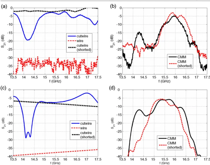
Figure 2. The ((a), (b)) measured and ((c), (d)) simulated transmission spectra of the composite metamaterial and individual components.
Cutwires show a magnetic resonance around 14.25 GHz, where the CMM exhibits a transmission peak.
the structure. We set the resonance frequency of the cutwire pairs to be close to 15 GHz and determined the corresponding geometrical parameters of the design, subject to constraints imposed by the substrate (e.g. layer thickness and dielectric constant of FR4). The simulation results are presented in figures 2(c) and (d). The simulation is performed on a unit cell with electric and magnetic boundary conditions in y and
zdirections. We also performed simulations on a finite CMM structure and confirmed that the result of the periodic structure is a good approximation for finite geometry.
The transmission spectrum of the CMM is measured using an HP8510C network analyser, a set of horn antennas and probe antennas. The measurements are taken in free space. We first measured the isolated components of the metamaterial, in order to identify their electric and magnetic resonances. Figure2(a) shows the transmission spectra of cutwire-only and wire-only structures. The wire-only structure is opaque, since the plasma cutoff frequency lies well above the measured frequency range. The cutwire-only structure has a stop band around 14.25 GHz. The cutwire essentially acts as an inductance–capacitance(LC)resonator. To show that this resonance gap is induced by the magnetic field component of the signal, a single cutwire pair is electrically shorted at its
edges by pinching holes in the dielectric layer and soldering the edges. The transmission spectrum of the shorted cutwire is measured by probe antennas. Since the current induced by the magnetic field can now circulate freely between the cutwire elements, the capacitance is removed. Therefore, the shorted cutwire pair (dashed black line) does not have any stop band, as seen in figure2(a).
The transmission spectrum of the CMM given in figure1(b) exhibits two transmission peaks (solid black line). To identify the peaks, we used a ‘shorted’ CMM sample (i.e. CMM containing shorted cutwire pairs). The shorted CMM roughly reproduces the transmission band between 15.25 and 16.5 GHz, but the peak located between 14.0 and 14.5 GHz is clearly absent. We note that the transmission band between 14.0 and 14.5 GHz coincides with the magnetic resonance stop band of the cutwire-only structure. In this range,ε <0, μ <0 and the transmission band can be identified as a left-handed peak. We further observe that the electric response of the CMM is significantly different from that of the wire-only structure, due to the presence of cutwires and evidently due to their additional electric response. This effect was also observed in SRR/wire type CMMs [8].
K Guven et al
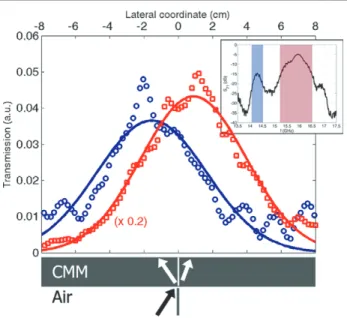
Figure 3. A simplified schematic of the refraction experiment is
indicated at the bottom of the figure. The lateral profiles of the measured electric field square|E|2at frequencies f = 14.30 GHz
(blue circles) and f = 15.85 GHz (red squares, downscaled to fit), and the respective Gaussian fits (lines) are plotted. The inset shows the transmission spectrum of the CMM with the left-handed and right-handed transmission bands indicated in colour shaded bands.
The simulated transmission spectra shown in figures2(c) and (d) agrees very well with the measurements, showing
all the essential resonance gaps and transmission peaks observed in the experiment. However, it is evident from the measurements that the present metamaterial structure suffers from high loss. This is partially due to the used dielectric substrate (FR4) which has a high loss tangent at microwave frequencies (typically about 0.012). For application purposes, the design should incorporate lower loss substrates. The highly dense continuous wire pattern also causes significant loss. A refined design based on a more sparse wire distribution may enhance the transmission level.
4. Negative refraction through the rectangular
metamaterial slab
In order to confirm the left-handed and right-handed identification of the transmission bands, we performed a refraction experiment on a rectangular slab of this metamaterial. We note that this is a quasi-one-dimensional metamaterial, for which the angle between the magnetic field vector and the short axis of the cutwire pair can affect the resonance strength, and thus the value of the effective permeability. Therefore, the refraction experiment is restricted to small incidence angles. In the experiment, a horn antenna emits the incident beam at θ = 10◦ to the normal of the metamaterial slab. The transmitted beam is measured along the exit surface of the metamaterial slab. This gives the lateral profile of the electric field squared |E(z)|2. A simplified schematic of the refraction experiment is shown at the bottom part of figure3.
Figure 4. The effective medium parameters obtained through a retrieval procedure from the simulated S parameters of a single metamaterial
layer. Note the negative real part of the index of refraction in the frequency range, which agrees with that of the measured left-handed transmission band.
The beam profiles at frequencies selected from the left-handed (f = 14.30 GHz) and from the right-handed transmission band (f = 14.85 GHz) are plotted in figure3. Evidently, the profile taken from the left-handed band shifted negatively, whereas the frequency selected within the right-handed band gives the usual positive refraction.
5. Effective permittivity and permeability functions
for the metamaterial
We employ a retrieval procedure to obtain the effective medium parameters of the metamaterial by using the simulated S -parameter spectra (transmission and reflection amplitude and phase as a function of frequency). Details of the retrieval procedure were reported previously in the literature [22,23]. For this purpose, a single layer of metamaterial is simulated, and theSparameters were obtained.
Figure 4 shows the effective index of refraction, n, obtained for the metamaterial. The computed real part of n
is negative within the frequency range where the left-handed transmission band is observed.
From the computed impedance and index of refraction, the effective permittivity and permeability functions are obtained and plotted in figure4. We emphasize that both have negative real parts in the left-handed transmission band.
6. Conclusion
In this paper, we report the design, fabrication, and experimen-tal and numerical investigation of a planar metamaterial struc-ture for normal-to-plane propagation at microwave regime. The metamaterial incorporates paired cutwires to achieve the magnetic resonance and hence the negative permeability re-sponse. The simulated and measured transmission spectra of the metamaterial exhibits a transmission band within a fre-quency band where the cutwire pairs have a magnetic reso-nance gap. The computed index of refraction is found to be negative within this transmission band. We have performed a refraction experiment using a multilayer slab of metamaterial and found that the incident electromagnetic field is refracted negatively. This metamaterial design can be employed in low-profile structures, and can be easily scaled to higher operation frequencies.
Acknowledgments
This work is supported by the European Union un-der the projects METAMORPHOSE, EU-NoE-PHOREMOST and TUBITAK under Projects Nos. 104E090, 105E066, 105A005 and 106A017. One of the authors (EO) also acknowledges partial support from the Turkish Academy of Sciences.
References
[1] Pendry J B, Holden A J, Stewart W J and Youngs I 1996 Extremely low frequency plasmons in metallic mesostructures Phys. Rev. Lett.76 4773
[2] Pendry J B, Holden A J, Robbins D J and Stewart W J 1999 Magnetism from conductors and enhanced nonlinear phenomena IEEE Trans. Microw. Theory Tech.47 2075
[3] Veselago V G 1968 The electrodynamics of substances with simultaneously negative values of permittivity and permeability Sov. Phys.—Usp.10 504
[4] Smith D R, Padilla W J, Vier D C, Nemat-Nasser S C and Schultz S 2000 Composite medium with simultaneously negative permeability and permittivity Phys. Rev. Lett. 84 4184
[5] Shelby R A, Smith D R and Schultz S 2001 Experimental verification of a negative index of refraction Science292 77 [6] Podolskiy V A, Sarchev A K and Shalaev V M 2003 Plasmon
modes and negative refraction in metal nanowire composites Opt. Express 11 735
[7] Shalaev V M, Cai W, Chettiar U K, Yuan H-K, Sarychev A K, Drachev V P and Kildishev A V 2005 Negative index of refraction in optical metamaterials Opt. Lett.30 3356 [8] Aydin K, Guven K, Kafesaki M, Zhang L, Soukoulis C M and
Ozbay E 2004 Experimental observation of true left-handed transmission peak in metamaterials Opt. Lett.26 2623 [9] Yen T J, Padilla W J, Fang N, Vier D C, Smith D R, Pendry J B,
Basov D N and Zhang X 2004 Terahertz magnetic response from artificial materials Science303 1494
[10] Linden S, Enkrich C, Wegener M, Zhou J, Koschny T and Soukoulis C M 2004 Magnetic response of metamaterials at 100 THz Science306 1351
[11] Enkrich C, Wegener M, Linden S, Zschiedrich L, Schmidt F, Zhou J F, Koschny T and Soukoulis C M 2005 Magnetic metamaterials at telecommunication and visible frequencies Phys. Rev. Lett.95 203901
[12] Zhang S, Fan W, Minhas B K, Frauenglass A, Malloy K J and Brueck S R J 2005 Mid-infrared resonant magnetic nanostructures exhibiting a negative permeability Phys. Rev. Lett.94 037402
[13] Klein M W, Enkrich C, Wegener M, Soukoulis C M and Linden S 2006 Single split-ring resonators at optical frequencies: limits of size scaling Opt. Lett.31 1259 [14] Moser H O, Casse B D F, Wilhelmi O and Saw B T 2005
Terahertz response of a microfabricated
rod-split-ring-resonator electromagnetic metamaterial Phys. Rev. Lett.94 063901
[15] Gokkavas M, Guven K, Bulu I, Aydin K, Kafesaki M, Penciu R, Soukoulis C M and Ozbay E 2006 Experimental demonstration of a left-handed metamaterial operating at 100 GHz Phys. Rev. B73 193103
[16] Dolling G, Enkrich C, Wegener M, Zhou J F, Soukoulis C M and Linden S 2005 Cut-wire pairs and plate pairs as magnetic atoms for optical metamaterials Opt. Lett.30 3198 [17] Zhou J, Zhang L, Tuttle G, Koschny T and Soukoulis C M 2006
Negative index materials using simple short wire pairs Phys. Rev.B73 041101
[18] Zhou J, Zhang L, Tuttle G, Koschny T and Soukoulis C M 2006 Experimental demonstration of negative index of refraction Appl. Phys. Lett.88 221103
[19] Zhang S, Fan W, Malloy K J, Brueck S R J, Panoiu N C and Osgood R M 2005 Near-infrared double negative metamaterials Opt. Express13 4922
[20] Zhang S, Fan W, Panoiu N C, Malloy K J, Osgood R M and Brueck S R J 2005 Experimental demonstration of near-infrared negative-index metamaterials Phys. Rev. Lett. 95 137404
[21] Dolling G, Enkrich C, Wegener M, Soukoulis C M and Linden S 2006 Low-loss negative-index metamaterial at communication wavelengths Opt. Lett.31 1800 [22] Chen X, Grzegorczyk T M, Wu B-I, Pacheco J and
Kong J A 2004 Phys. Rev. E70 016608
[23] Smith D R, Vier D C, Koschny T and Soukoulis C M 2005 Phys. Rev. E71 036617