PIECEWISE LINEAR ASYMPTOTIC WAVEFORM EVALUATION
FOR TRANSIENT SIMULATION OF ELECTRONIC CIRCUITS
C.T.
Dikmen,M.M.
Alaybeyit,S.
Topcu, A. Atalar, E. Sezer, M . A . Tan, R.A. RohrertBilkent University, Ankara,
TURKEY
t
Carnegie Mellon University, Pittsburgh PA, U.S.A.Abstract
A general purpose circuit simulation program, PL- AWE, is developed especially for the analysis of VLSI circuits. PL-AWE uses Asymptotic Waveform Evalua- tion (AWE) technique, which is a new method to an- alyze linear(ized) circuits, and piece-wise-linear (PL) models to represent nonlinear elements. AWE employs a form of Pad6 approximation rather than numerical integration to approximate the behavior of linear(ized) circuits in either the time or the frequency domain.
I.
Introduction
PL-AWE (Piecewise Linear Asymptotic Waveform Evaluator) is a general purpose circuit simulation program, suitable espe- cially for the transient analysis of nonlinear electronic circuits. PL-AWE solves large circuits containing linear energy storage elements and passive and active linear or nonlinear resistive elements. PL-AWE uses Asymptotic Waveform Evaluation (AWE) [l] in conjunction with Piecewise Linear (PL) models for the dc representation of nonlinear devices.
For dc nonlinear circuit simulation PL analysis is attractive be- cause it can provide the following features: robustness, compu- tational efficiency, and a clearly defined accuracy/speed trade- off. Robustness (i.e., convergence) is achieved by starting dc analysis from the known ground state a t the origin when all independent sources are off. Then the dc steady state can be obtained effectively by "corner hopping" [2] using a modified Katzenelson algorithm [3,4], where PL segment transitions are made only at their corners.
But problems arise in attempts to extend efficient PL analysis to the time domain transient situation. To retain efficiency in corner hopping, PL analysis must be combined with ex- plicit integration methods such as Forward Euler. But explicit integration algorithms are notoriously unstable, which often dictates that extremely small time steps be taken. Such small time steps may overwhelm the potential efficiency of PL sim- ulation. Implicit integration algorithms such as Backward Eu- ler, are stable, but they are not compatible with efficient corner huppi,., because an iterative solution must be mounted to at- tain such corners. What is required for efficient PL transient analysis is a stable explicit integration algorithm; Asymptotic
Waveform Evaluation (AWE) technique can efficiently satisfy such a requirement [ 5 ] .
PL-AWE is a time domain nonlinear circuit simulator based on a combination of PL analysis and suitably modified Asymp- totic Waveform Evaluation. In this paper we discuss in detail the internal workings of the program, and indicate its effec- tiveness in terms of several illustrative examples.
11.
Modeling
of
Nonlinear Devices and
DC Analysis
PL-AWE employs table models t o describe two and three- terminal nonlinear devices and the user has the flexibility to enter his own device models. A two-terminal nonlinear device is represented by a linear terminal equation of the form
av
+
b i + c = 0in every segment of the (v, i) plane. Similarly, a three-terminal nonlinear device consists of a set of regions in the ( V I , v2, i l , i z )
space. Every region is represented in terms of two linear ter- minal equations of the form
allivl
+
a2kv2+
b i k i l+
b 2 k i 2+
Ck = 0, k = 1,2 It is assumed that for every nonlinear device there is a seg- ment/region which contains the origin of the space of terminal variables within its boundaries. That is, all nonlinear devices with the exception of independent sources are assumed t o pos- sess a ground state of v = 0 and i = 0.The use of PL approximation results in a set of linear equa- tions and hence the iterative solutions of nonlinear equations are avoided. Since AWE applies only t o linear(ized) circuits, the use of PL approximation makes the utilization of AWE easy and efficient for nonlinear devices. The PL approximation also gives the user the flexibility of defining his own device models for nonlinear devices and enables the user t o determine the trade-off between the speed and accuracy of the simulation. I t should be noted that the accuracy of PL models for non- linear devices depends on the number of regions into which the terminal equations are linearized. However, as the number of segments increases, the complexity of the analysis may in- crease dramatically. Nevertheless, it is observed that, with the
inclusion of parasitic capacitances, models of diodes and tran- sistors with only a few segments (2 segments for diodes and 4 segments for MOSFETs) yield quite good results for timing analysis.
PL-AWE employs a modified version of h‘attenelson’s algo-
rithm [3, 41 t o find the operating segments of PL elements and compute the dc solution. In dc analysis, all capacitors and in- ductors are replaced by independent sources forcing their ini- tial condition. Starting from a valid solution for an arbitrary input, the algorithm computes the solution for a given input in an iterative manner. Using this algorithm, convergence is guaranteed for dc analysis.
111.
Transient
Analysis
In timing analysis, PL-AWE computes the transient response of the outputs as a function of time over a user specified time interval. In addition to the independent dc sources, any in- dependent source can be assigned a time-dependent value for transient analysis. Ideal step changes in the time-dependent sources are also handled without loss of generality. The tran- sient response is computed using AWE rather than numerical integration methods to approximate the response of energy storage elements (state variables) in the time domain. Us- ing AWE, we obtain approximate analytic expressions, for the state variables, of the form
where the p z 7 s are the approximate dominant poles, the k,’s are their corresponding residues for that state variable, q is the order of approximation in AWE and c is a constant term. In obtaining the approximate poles and residues, AWE employs Pad6 approximation [6, 7, 81 and matches the initial condition and the first ( 2 q - 1) integral moments of x a ( t ) to those of z ( t ) .
An important deficiency of AWE is that it may produce un- stable right half plane poles even though the circuit is stable, which is also a major problem encountered with Pad6 approx- imation. This problem is overcome in PL-AWE by combining the derivative moments with the integral moments, and AWE is extended t o match both the derivative and the integral mo- ments t o overcome the unstability problem. Other researchers in this area have also stated the use of derivative moments in AWE [9]. The integral moments provide information about the integrals of the actual response. They correspond to the coeffi- cients of the Taylor series expansion of the Laplace Transform of the original response around s = 0. The derivative mo- ments, on the other hand, are the successive derivatives of the response at t = 0, and correspond t o the coefficients of an ex- pansion about infinity of X ( s ) in s-’. For the calculation of approximate poles and residues, every state variable is treated independently and an appropriate combination of derivative and integral moments is used. The algorithm utilized for this purpose can be summarized as follows. An integral moment is replaced by a derivative moment until a stable approximation is found or all of the integral moments are used up. If a sta- ble approximation cannot be found by shifting from integral
t o derivative moments, then the order of approximation is in- creased by one. Note that, using this algorithm, the order of approximation and the number of derivative moments used in the approximation need not be the same for the different state variables.
Using AWE, w e obtain approximate analytic expressions for capacitor voltages and inductor currents. These expressions are valid over all future time as long as PL elements continue to satisfy the present set of operating regions. These expres- sions are evaluated a t certain time instants, and the voltage and current values obtained are used in a mere substitution t o calculate the voltage and current of every device. When a segment/region change occurs the capacitor voltages and in- ductor currents for that instant of time are the initial condi- tions for a new dc analysis over new segments/regions for the PL devices. Then, a new AWE is performed using the new segments/regions and the new initial conditions.
A similar procedure must be followed when there is an input change a t time t o . We evaluate the approximate expressions found for energy storage elements and solve the circuit at time
t i . A new dc analysis is performed a t time t i using the new
source vector, and a new AWE is carried out for t 2 to. For dc analysis, we can use the previous solution and segments (instead of the 0 vector) as the initial valid solution. This saves a lot of Computation in dc analysis.
The selection of the time step in transient analysis is a critical issue from the computation time efficiency standpoint. There- fore, the internal time step used in the transient analysis is dy- namically calculated after each iteration. In this calculation, we consider primarily the rate of change of the most rapidly changing exponential. As a result of this dynamic selection of the time step, the simulator expends more effort when there are rapid voltage or current variations, and progresses faster over the time axis otherwise. This approach provides dynamic latency and an event driven character t o the simulator. Another facility of PL-AWE is that the user can observe dy- namically the operating segments of PL devices. This facility is a lot of help t o the user, because it is relatively easy to understand the operation of PL models which are commonly used for nonlinear devices. We believe that PL-AWE provides instructive feedback from this point of view since the solution style is very similar to a manual solution.
IV.
Results
In this section, we present some results obtained by PL-AWE to demonstrate its accuracy and efficiency. The program leaves the accuracy speed trade-off to the user by giving him/her a number of options. The minimum order of approsimation which determines the number of moments matched in <4WE is an important parameter for the accuracy of the approxima- tion. The minimum order and also the number of derivative moments that will be matched initially can be determined by the user. There are also some other parameters that can be set by the user to improve the accuracy or the speed. Another important feature is that, user can define his/her own mod- els (or use those from the library) for nonlinear devices. This
0 - PL-AWE c)-t. SPICE-I SPICE 2
0
0 0 0
‘0. OOn time (sec) 2 0 0 . o o d
Figure 1: The output voltage of the CMOS inverter. SPICE-1 and SPICE-:! are the SPICE simulations using 50 and 400 time steps, respectively.
provides a capability of keeping pace with the emerging tech- nology and user can control the accuracy speed trade-off by choosing the number of segments used for modeling. PL-AWE has been implemented in the C Programming language on SUN Workstations running under SunOS 4.1 and DEC Worksta- tions running under Ultrix. Input cards for PL-A4WE is the same as SPICE input, except the model card.
EXAMPLES:
The first example is a CMOS inverter with two complenien- tary transistors. Both type of transistors are modeled with 4 regions: cutoff, linear, saturation and inverse saturation. The regions are modified appropriately with W/L ratio of transis- tors. To represent a typical transistor, parasitic capacitors are also included in the device model. The inverter is loaded with a 2-pF capacitor. The input waveform contains two pulses. A transient analysis is performed using SPICE’ and PL-AWE with varying time steps (Fig. 1). PL-AWE transient analysis results with varying time steps do not differ, since the response is known analytically. The simulation result of PL-AVC‘E is very close to the result of SPICE with large number of steps (ex- pected to be more accurate). The normalized rms difference2 between the PL-AWE and SPICE simulations is about 3% and PL-AWE is 4 times faster than SPICE. Although PL-AWE uses simple PL models for transistors, its result is more accu- rate than SPICE with inappropriate transient time step. The second example is a diode transmission gate with 3 diodes driving a parallel RC circuit. The diode characteristics is mod- eled with two segments, one representing the OFF region and the other is the ON region. A transient analysis is performed with SPICE and PL-AWE with a square-wave input and the results are given in Fig. 2. The normalized rms difference be- tween the two simulation results is less than 2% and PL-AWE is 6 times faster than SPICE.
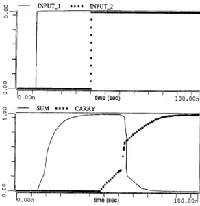
The third example is a CMOS Full Adder with 28 MOSFET’s. The outputs CARRY and SUM are loaded with 1-pF capac- ’SPICE 2G.6 in SUN-3/60 iVorkstations is used in all the SPICE simulations. 2 E 0 -m - ro r( rn
-
PL-AWE--..
SPICE - - E r i ro ID I I I I I I I I I I I I Y ~ O . O O r n time (sec) 5 . 0 0Figure 2: The transient analysis result for the voltage across the RC circuit connected t o the diode transmission gate.
itors. In PL models, parasitic capacitors of MOSFET’s are made proportional to transistor areas. The adder is simulated using SPICE and PL-AWE and the results of PL-AWE are shown in Fig. 3. The propagation delay through gates can be observed in outputs CARRY and SUM. We were unable t o compare it with SPICE, because it gives the familiar “internal time step too small” error message and aborts the execution in spite of many trials in the option card.
time (sec)
,i
Figure 3: Input and output waveforms for CMOS Full-Adder circuit as obtained by PL-AWE.
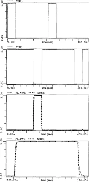
The last example is a CMOS address decoder circuit which contains 56 transistors. A transient analysis is performed using PL-AWE and SPICE with varying time steps (Fig. 4). The simulation results are almost identical, but PL-AWE executes 7 times faster than SPICE. The output delay time is 330 psec. for PL-AWE, and it is 500, 900, 1300 psec. for SPICE using 100, 500, 1000 psec. transient time steps, respectively.
Figure 4: The results of transient analysis of the address de- coder circuit. The first two waveforms are the inputs, the third is the output, and the last waveform is a zoomed view of it.
VI. Conclusions
A new general purpose circuit simulation tool, PL-AWE, has been developed using AWE and PL models. PL-AWE is not yet optimized for execution efficiency, but its performance is very good. It is observed that the relative performance of the program increases as the size of the circuit grows. Some of the results we obtained are:
Using different combinations of derivative and integral moments for each state variable, instability problem of AWE is overcome.
PL approach guarantees the convergence in dc analysis. Accuracy speed trade-off is achieved by user-defined PL models.
Adaptive calculation of the time step provides an activity driven feature.
Simple models of nonlinear devices with few segments give quite good results for transient analysis.
PL-AWE makes it easier to understand the behavior of the circuit by depicting the operating segments/regions of the PL devices.
As a result, PL-AWE can be used effectively in the analysis of digital VLSI and analog integrated circuits.
Acknowledgment: This work was partially supported by NATO’s
Scientific Affairs Division in the framework of the Science for Stability Programme.
References
L.T. Pillage
,
R.A. Rohrer. “Asymptotic Waveform Evalu- ation for Timing bnalysis,” IEEE Trans. Computer-Aided Design, Vol. 9, No. 4, pp. 352-366, April 1990.T. Fujisawa, E.S. Kuh. “Piecewise-Linear Theory of Non- linear Networks,” J . Appl. Math.
,
Vol. 22,
No. 2, pp. 307-328, March 1972.M. J. Chien, E.S. Kuh. “Solving Nonlinear Resistive Net- works Using Piecewise-Linear Analysis and Simplical Sub- division,” IEEE Trans. on Circuits and Systems, Vol. 24,
pp. 305-317, June 1977.
H.J. Strayer, D.J. Roulston, P.R. Bryant. “DC Solution Speed in Piecewise Linear Network Analysis Programs,”
Elect. Lett.
,
Vol. 22,
No .3, pp. 165-166, January 1986. L.T. Pillage. “Asymptotic Waveform Evaluation for Tim- ing Analysis,” Ph.D. Dissertation, Carnegie Mellon Uni- versity, Pennsylvania, USA, 1989.C.F. Chen, L.S. Shieh. “A Novel Approach to Linear Model Simplification,” Int. J . Control, Vol. 8, No. 6, pp.
561-570, 1968.
V. Zakian. “Simplification of Linear Time-Invariant Sys- tems by Moment Approximants,” Int. J . Control, Vol. 18,
No. 3, pp. 455-460,1973.
M.J. Bosley, H.W. Kropholler, F.P. Lees. “On the Rela- tion Between the Continued Fraction Expansion and Mo- ments Matching Methods of Model Reduction,” Int. J . Control, Vol. 18, No. 3, pp. 461-474, 1973.
X. Huang, V. Raghavan, R.A. Rohrer. AWEsim: A pro- gram for the efficient analysis of linear(ized) circuits. In “Technical Digest of the IEEE International Conference on Computer-Aided Design”, pp. 542-545, 1990.